EP1152574A2 - Système de commutation de paquets et procédé - Google Patents
Système de commutation de paquets et procédé Download PDFInfo
- Publication number
- EP1152574A2 EP1152574A2 EP01108657A EP01108657A EP1152574A2 EP 1152574 A2 EP1152574 A2 EP 1152574A2 EP 01108657 A EP01108657 A EP 01108657A EP 01108657 A EP01108657 A EP 01108657A EP 1152574 A2 EP1152574 A2 EP 1152574A2
- Authority
- EP
- European Patent Office
- Prior art keywords
- priority
- output
- packet
- queues
- switch
- Prior art date
- Legal status (The legal status is an assumption and is not a legal conclusion. Google has not performed a legal analysis and makes no representation as to the accuracy of the status listed.)
- Granted
Links
Images


Classifications
-
- H—ELECTRICITY
- H04—ELECTRIC COMMUNICATION TECHNIQUE
- H04L—TRANSMISSION OF DIGITAL INFORMATION, e.g. TELEGRAPHIC COMMUNICATION
- H04L49/00—Packet switching elements
- H04L49/15—Interconnection of switching modules
- H04L49/1515—Non-blocking multistage, e.g. Clos
- H04L49/153—ATM switching fabrics having parallel switch planes
-
- H—ELECTRICITY
- H04—ELECTRIC COMMUNICATION TECHNIQUE
- H04L—TRANSMISSION OF DIGITAL INFORMATION, e.g. TELEGRAPHIC COMMUNICATION
- H04L49/00—Packet switching elements
- H04L49/25—Routing or path finding in a switch fabric
- H04L49/253—Routing or path finding in a switch fabric using establishment or release of connections between ports
- H04L49/255—Control mechanisms for ATM switching fabrics
-
- H—ELECTRICITY
- H04—ELECTRIC COMMUNICATION TECHNIQUE
- H04L—TRANSMISSION OF DIGITAL INFORMATION, e.g. TELEGRAPHIC COMMUNICATION
- H04L49/00—Packet switching elements
- H04L49/55—Prevention, detection or correction of errors
- H04L49/552—Prevention, detection or correction of errors by ensuring the integrity of packets received through redundant connections
-
- H—ELECTRICITY
- H04—ELECTRIC COMMUNICATION TECHNIQUE
- H04L—TRANSMISSION OF DIGITAL INFORMATION, e.g. TELEGRAPHIC COMMUNICATION
- H04L12/00—Data switching networks
- H04L12/54—Store-and-forward switching systems
- H04L12/56—Packet switching systems
- H04L12/5601—Transfer mode dependent, e.g. ATM
- H04L2012/5625—Operations, administration and maintenance [OAM]
- H04L2012/5627—Fault tolerance and recovery
-
- H—ELECTRICITY
- H04—ELECTRIC COMMUNICATION TECHNIQUE
- H04L—TRANSMISSION OF DIGITAL INFORMATION, e.g. TELEGRAPHIC COMMUNICATION
- H04L12/00—Data switching networks
- H04L12/54—Store-and-forward switching systems
- H04L12/56—Packet switching systems
- H04L12/5601—Transfer mode dependent, e.g. ATM
- H04L2012/5638—Services, e.g. multimedia, GOS, QOS
- H04L2012/5646—Cell characteristics, e.g. loss, delay, jitter, sequence integrity
- H04L2012/565—Sequence integrity
-
- H—ELECTRICITY
- H04—ELECTRIC COMMUNICATION TECHNIQUE
- H04L—TRANSMISSION OF DIGITAL INFORMATION, e.g. TELEGRAPHIC COMMUNICATION
- H04L12/00—Data switching networks
- H04L12/54—Store-and-forward switching systems
- H04L12/56—Packet switching systems
- H04L12/5601—Transfer mode dependent, e.g. ATM
- H04L2012/5638—Services, e.g. multimedia, GOS, QOS
- H04L2012/5646—Cell characteristics, e.g. loss, delay, jitter, sequence integrity
- H04L2012/5651—Priority, marking, classes
-
- H—ELECTRICITY
- H04—ELECTRIC COMMUNICATION TECHNIQUE
- H04L—TRANSMISSION OF DIGITAL INFORMATION, e.g. TELEGRAPHIC COMMUNICATION
- H04L12/00—Data switching networks
- H04L12/54—Store-and-forward switching systems
- H04L12/56—Packet switching systems
- H04L12/5601—Transfer mode dependent, e.g. ATM
- H04L2012/5678—Traffic aspects, e.g. arbitration, load balancing, smoothing, buffer management
- H04L2012/5681—Buffer or queue management
-
- H—ELECTRICITY
- H04—ELECTRIC COMMUNICATION TECHNIQUE
- H04L—TRANSMISSION OF DIGITAL INFORMATION, e.g. TELEGRAPHIC COMMUNICATION
- H04L49/00—Packet switching elements
- H04L49/20—Support for services
- H04L49/205—Quality of Service based
- H04L49/206—Real Time traffic
-
- H—ELECTRICITY
- H04—ELECTRIC COMMUNICATION TECHNIQUE
- H04L—TRANSMISSION OF DIGITAL INFORMATION, e.g. TELEGRAPHIC COMMUNICATION
- H04L49/00—Packet switching elements
- H04L49/30—Peripheral units, e.g. input or output ports
- H04L49/3027—Output queuing
Definitions
- the present invention relates to packet switching techniques, and in particular to packet switching system and method ensuring traffic quality.
- LANs local-area networks
- IP(Internet Protocol)-based private networks have been widely used in companies and universities and are undergoing further development to carrier-class public networks.
- QoS Quality of Service
- An ATM (asynchronous transfer mode) cell switching system guaranteeing the sequence and continuity of cells has been disclosed in Japanese Patent Application Unexamined Publication No. 5-7213. More specifically. the conventional switching system is provided with working and reserved ATM cell switches, which are selectively connected to an outgoing line by a system selector. When the working ATM cell switch is switched to the reserved ATM cell switch, the system switching is performed after all the cells staying in the working ATM cell switch have been completely forwarded to the outgoing line.
- This cell switching technique can be also applied to IP packet switching systems.
- an end terminal In general, in the case of real-time traffic, an end terminal is provided with a buffer for absorbing variations in arrival time of packets. However, it is necessary for packets to arrive within a predetermined delay time. For example, telephone conversation cannot be don smoothly without limiting a delay time to at most several hundredmilliseconds. If a packet is delayed by a time interval longer than an absorbable time period, then the packet is assumed not to arrive and is interpolated, or equivalently loss of packet.
- An object of the present invention is to provide a packet switching system and method capable of ensuring the sequence and continuity of packets and further compensating for delays in transmission.
- Another object of the present invention is to provide a packet switching method and system capable of maintaining QoS guarantees for individual traffic flows including traffic that requires small delays and traffic that does not require small delays.
- the controller monitors a packet storing status of each of the M priority queues and, if the one of the two priority queues corresponding to respective ones of the two switch sections becomes empty, then the controller instructs the output selector to select the other of the two priority queues to store an output of the selected one into a corresponding one of the M priority output queues.
- Each of the switch sections may further include a readout controller controlling a packet reading sequence of the M priority queues for each of the N buffers such that priority in packet reading is given to a higher priority queue.
- the controller may instruct the output selector to sequentially select the other of the two priority queues for each of the M priorities in descending order of priority.
- Each of the switch sections may further include a readout controller controlling a packet reading sequence of the high-priority and low-priority queues for each of the N buffers such that priority in packet reading is given to the high-priority queue.
- the readout controller may start reading out low-priority packet stored in the low-priority queue after all high-priority packets stored in the high-priority queue have been completely read out.
- the readout controller may control a packet reading sequence of the high-priority and low-priority queues for each of the N buffers such that m high-priority packets are read out from the high-priority queue and n low-priority packets are read out from the low-priority queue, wherein m is set to be greater than n.
- the step (b) may include the steps of: when the one of the two switch routes is switched to the other by the system switching signal, monitoring a packet storing status of each of the M priority queues; and when the one of the two priority queues corresponding to respective ones of the two switch sections becomes empty, selecting the other of the two priority queues Lo store an output of the selected one into a corresponding one of the M priority output queues.
- the output selector switches from the working switch route to a reserved switch route to store packets into a high-priority output queue independently of a packet storing status of the low-priority queue. Accordingly, traffic requiring small delay can be switched rapidly. avoiding deterioration in traffic delay property.
- the present invention has the following advantages:
- a packet switching system is provided with N (N is an integer greater than 0) input processors 1.1 to 1.N, which are connected to respective ones of N input lines IN.1 to IN.N.
- the respective input processors 1.1 to 1.N are connected to N input selector switches 2.1 to 2.N, each of which outputs a packet of data to a selected one of two switch sections 31 and 32.
- Each of the switch sections 31 and 32 has N output ports corresponding to respective ones of N output lines OUT. 1 to OUT.N. More specifically, a pair of corresponding output ports of the switch sections 31 and 32 are connected to a corresponding one of N output selectors 4.1 to 4.N, which are connected to N output processors 5.1 to 5.N, respectively.
- a switch controller 6 controls selection operations of the output selectors 4.1 to 4.N based on status signals received from the switch sections 31 and 32, which will be described later.
- the respective input processors 1.1 to I.N perform input processing of packets received from the input lines IN.1 to IN.N.
- the input processing includes: counting the number of packets; discarding packets going over the speed limit; checking the priority of a packet; and searching for destination port.
- the input selector switch when receiving a packet from a corresponding input processor. outputs the packet to a selected one of the switch sections 31 and 32.
- the switch section 31 includes an N x N switch fabric 312. which may be a crossbar switch or configured in bus form.
- the N input ports of the switch fabric 312 are connected to respective ones of the input selector switches 2.1 to 2.N.
- the N output ports of the switch fabric 312 are connected to respective ones of N output buffers 313.1 to 313.N.
- the switch section 32 includes an N x N switch fabric 322, which may be a crossbar switch or configured in bus form.
- the N input ports of the switch fabric 322 are connected to respective ones of the input selector switches 2.1 to 2.N.
- the N output ports of the switch fabric 322 are connected to respective ones of N output buffers 323.1 to 323.N.
- each of the output buffers 313.1 to 313.N includes M priority queues each corresponding to different priorities of packets, where M is an integer greater than 1.
- the priority of a packet indicates how fast the packet passes through the switch. In other words, a packet with higher priority is given priority in transfer to its destination port.
- a packet that requires a shorter delay time is a high-priority packet and one that does not require a snorter delay time is a low-priority packet. Therefore, a high-priority packet is expected to pass through the switch faster than a low-priority packet.
- Each of the output processors 5.1 to 5.N receives a packet from a corresponding output selector and performs necessary processing of the packet to output it to a corresponding output line.
- the processing performed in the output processor includes counting the number of outgoing packets and controlling the transfer rate.
- each of the output buffers 313.1 to 313.N includes two priority queues: high-priority queue and low-priority queue.
- a high-priority packet is stored in the high-priority queue and a low-priority packet is stored in the low-priority queue in each output buffer.
- the output buffer is provided with a distributor 7, a high-priority queue 8, a low-priority queue 9, a queue-output selector 10, and a readout controller 11.
- the distributor 7 receives packets from a corresponding output port of the switch fabric and discriminates between a high-priority packet and a low-priority packet.
- the high-priority packet is stored in a high-priority queue 8 and the low-priority packet is stored in a low-priority queue 9.
- the distributor 7 does not necessarily check the header information of each packet to determine its priority.
- Each of the input processors 1.1 to 1.N reads the header of a packet to determine whether the packet is a high-priority packet or a low-priority packet and then adds to the packet internally effective bit information indicating whether the packet is a high-priority packet or a low-priority packet. Therefore, only by looking at the added bit information, the distributor 7 can discriminate between a high-priority packet and a low-priority packet.
- the high-priority queue 8 and the low-priority queue 9 output respective status signals to the readout controller 11 and the switch controller 6.
- the status signal of the high-priority queue 8 or the low-priority queue 9 indicates an empty status when no packet is stored therein.
- the high-priority queue 8 and the low-priority queue 9 output respective packets to the queue-output selector 10 depending on output permission signals received from the readout controller 11. More specifically, only when the output permission signal is received, a corresponding queue outputs a stored packet to the queue-output selector 10. If the output permission signal is not received, then the corresponding queue does not output any packet to the queue-output selector 10.
- the readout controller 11 outputs the output permission signals to respective ones of the high-priority queue 8 and the low-priority queue 9 and further outputs a selection signal SEL to the queue-output selector 10, depending on the status signals received from respective ones of the high-priority queue 8 and the low-priority queue 9,
- the queue-output selector 10 selects one of the outputs of the high-priority queue 8 and the low-priority queue 9 depending on the selection signal SEL. For example, when the readout controller 11 outputs the output permission signal to the high-priority queue 8, the readout controller 11 outputs the selection signal SEL to the queue-output selector 10 so that the output of the high-priority queue 8 is selected.
- the queue-output selector 10 selects the output of the low-priority queue 9.
- a packet selected by the queue-output selector 10 in an output buffer is output to a corresponding output selector.
- the readout controller 11 In the case where one of the high-priority queue 8 and the low-priority queue 9 does not output the empty status signal, in other words, the one stores at least one packet and the other is empty, the readout controller 11 outputs the output permission signal only to the one of the high-priority queue 8 and the low-priority queue 9 and thereby the one is permitted to output a packet to the queue-output selector 10.
- the readout controller 11 outputs the output permission signal only to the high-priority queue 8. Accordingly, when the high-priority queue 8 and the low-priority queue 9 both store at least one packet, only the high-priority queue 8 is permit Led to output a packet to the queue-output selector 10 and the low-priority queue 8 is not permitted to output a packet until the high-priority queue 8 has completely output the abiding packets. In other words, after the high-priority queue 8 becomes empty, that is, the high-priority queue 8 outputs the empty status signal, the output permission signal is output to the low-priority queue 8.
- the packets stored in the high-priority queue 8 are given priority in transfer independently of the status of the low-priority queue 9. After all the abiding packets have been completely transferred from the high-priority queue 8, packets stored in the low-priority queue 9 are output to the queue-output selector 10.
- the readout controller 11 outputs the output permission signal only to the one of the high-priority queue 8 and the low-priority queue 9 and thereby the one is permitted to output a packet to the queue-output selector 10,
- the readout controller 11 outputs the output permission signal to the high-priority queue 8 so that M packets are output from the high-priority queue 8 and outputs the output permission signal to the low-priority queue 9 so that N packets are output from the low-priority queue 9, where M > N. Accordingly, when Lhe high-priority queue 8 and the low-priority queue 9 both store at least one packet, packets are read out from the high-priority queue 8 more frequently than from the low-priority queue 9. therefore, compared with low-priority packets, high-priority packets pass through the switch with smaller delay.
- the readout control is performed based on the number of packets transferred, it can be also performed based on the number of bytes of packets transferred.
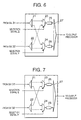
- the output selector is provided with distributors 21 and 22, which are connected to respective ones of the switch sections 31 and 32.
- a high-priority packet selector 23 is connected to the outputs of the distributors 21 and 22 and outputs only high-priority packets to a high-priority queue 25.
- a low-priority packet selector 24 is connected to the outputs of the distributors 21 and 22 and outputs only low-priority packets to a low-priority queue 26.
- the outputs of the high-priority queue 25 and the low-priority queue 26 are connected to a readout section 27.
- the distributor 21 receives packets from the switch section 31 and discriminates between a high-priority packet and a low-priority packet.
- the high-priority packet is output to the high-priority packet selector 23 and the low-priority packet is output to the low-priority packet selector 24.
- the distributor 22 receives packets from the switch section 32 and discriminates between a high-priority packet and a low-priority packet.
- the high-priority packet is output to the high-priority packet selector 23 and the low-priority packet is output to the low-priority packet selector 24.
- the distributors 21 and 22 can discriminate between a high-priority packet and a low-priority packet only by looking at the added bit information of the packet.
- the high-priority packet selector 23 selects one of high-priority packets received from the switch sections 31 and 32 to output it to the high-priority queue 25 depending on a selection signal E received from the switch controller 6.
- the low-priority packet selector 24 selects one of low-priority packets received from the switch sections 31 and 32 to output it to the low-priority queue 26 depending on a selection signal F received from the switch controller 6.
- the high-priority packet selector 23 finally determines the switching timing of high-priority packet between the switch sections 31 and 32 and the low-priority packet selector 24 finally determines the switching timing of low-priority packet between the switch sections 31 and 32.
- high-priority packets stored in the high-priority queue 25 and low-priority packets stored in the low-priority queue 26 are read out and output to a corresponding output processor by the readout section 27.
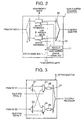
- the switch controller 6 includes N selection signal generators 6.1 to 6.N, which correspond to the output selectors 4.1 to 4.N, respectively.
- the selection signal generators 6.i (i is an integer: 1 ⁇ i ⁇ N) receives high-priority and low-priority status signals A and B from the output buffer 313.i of the switch section 31, high-priority and low-priority status signals C and D from the output buffer 323.i of the switch section 32, and a system switching signal S instructing the switching between the switch sections 31 and 32.
- the selection signal generators 6.i generates the selection signals E and F based on the status signals A, B, C, and D and the system switching signal S to output them to the output selector 4.i.
- the selection signal generator 6.i determines whether the system switching signal S is received (step S1).
- the selection signal generator 6.1 monitors the high-priority and low-priority status signals A and B of the output buffer 313.i and the high-priority and low-priority status signals C and D of the output buffer 323.i (step S2).
- the selection signal generators 6.i generates selection signals E and F according to predetermined logic as shown in Table (step S3). Thereafter, it is determined whether the high-priority and low-priority queues of a corresponding output buffer become cmpty (step S4) and, if all queues are empty. then control goes back to the step S1.
- the low-priority queue 9 of the output buffer 313.1 becomes empty, the low-priority queue status signal B is changed from 0 to 1 and the selection signal generators 6.1 changes the selection signal F from 0 to 1.
- each of the selection signal generators 6.1 to 6.N of the switch controller 6 generates selection signals E and F based on the status signals A, B, C, and D and the system switching signal S to control the switching of the high-priority and low-priority packet selectors 23 and 24 of a corresponding output selector.
- a packet switching operation in the redundant system as shown in Fig. 1 will be described with reference to Figs. 6-8. It is assumed for simplicity that a packet received from the input line IN.1 is switched from the working switch section 31 to the reserved switch section 32 to be forwarded to the output line OUT.1.
- the output buffer 313.1 of the switch section 31 receives packets from a corresponding output port of the switch fabric and selectively stores the packets in the high-priority queue 8 and the low-priority packet 9 depending on the priority of each packet.
- the queue-output selector 10 reads out packets from a selected one of the high-priority queue 8 and the low-priority packet 9 according to a predetermined readout control method as described before. The readout packet is output to the output selector 4.1.
- the output selector 4.1 is set to such a status that the high-priority packet selector 23 and the low-priority packet selector 24 both select the outputs of the distributor 21 corresponding to the working switch section 31. Therefore, a high-priority packet output from the distributor 21 is stored in the high-priority packet queue 25 through the selector 23 and a low-priority packet output from the distributor 21 is stored in the low-priority packet queue 26 through the selector 24.
- the input selector switch 2.1 switches the forwarding destination of a received packet from the working switch section 31 to the reserved switch section 32 (see Fig. 1).
- packets are selectively stored in the high-priority queue 8 and the low-priority packet 9 in the output buffer 323.1 of the reserved switch section 32 depending on the priority of each packet.
- the packets stored in the buffers 8 and 9 of the working switch section 31 continue to be read out according to the predetermined readout control method and are stored in a corresponding one of the high-priority packet queue 25 and the low-priority packet queue 26.
- the packets stored in the high-priority queue 8 are given priority in transfer as described before.
- the selector 23 of the output selector 4.1 is changed to such a status that a high-priority packet is received from the distributor 22 corresponding to the reserved switch section 32. Accordingly, the high-priority packets stored in the high-priority queue 8 of the output buffer 323.1 in the reserved switch section 32 are distributed to the selector 23 by the distributor 22 and stored in the high-priority packet queue 25. In other words, from the viewpoint of a high-priority packet, a switch to be passed through is switched from the working switch section 31 to the reserved switch section 32. Therefore, when the system is switched from working to reserved, a high-priority packet passes through the switch without staying in the reserved switch section 32 for a long time, resulting in a small amount of delay.
- the switching timing between working and reserved switch sections varies depending on the priority of a packet. More specifically, the higher the priority of a packet, the earlier the switching timing. Therefore, traffic flows requiring real-time transfer can be switched with little delay.
- the above-described operation is performed in each of the output buffers.
- two kinds of queues (high-priority and low-priority queues) are provided for each output buffer. It is possible to define three or more priority classes by providing three or more kinds of queues in each output buffer.
- the buffer is provided at the output side of the switch fabric in the above embodiment, it is possible to provide the buffer at the input side of the switch fabric.
Landscapes
- Engineering & Computer Science (AREA)
- Computer Networks & Wireless Communication (AREA)
- Signal Processing (AREA)
- Computer Security & Cryptography (AREA)
- Data Exchanges In Wide-Area Networks (AREA)
- Exchange Systems With Centralized Control (AREA)
- Time-Division Multiplex Systems (AREA)
- Monitoring And Testing Of Exchanges (AREA)
Applications Claiming Priority (2)
| Application Number | Priority Date | Filing Date | Title |
|---|---|---|---|
| JP2000104707 | 2000-04-06 | ||
| JP2000104707A JP2001292164A (ja) | 2000-04-06 | 2000-04-06 | パケット・スイッチおよびその切替方法 |
Publications (3)
| Publication Number | Publication Date |
|---|---|
| EP1152574A2 true EP1152574A2 (fr) | 2001-11-07 |
| EP1152574A3 EP1152574A3 (fr) | 2003-05-14 |
| EP1152574B1 EP1152574B1 (fr) | 2006-06-21 |
Family
ID=18618203
Family Applications (1)
| Application Number | Title | Priority Date | Filing Date |
|---|---|---|---|
| EP20010108657 Expired - Lifetime EP1152574B1 (fr) | 2000-04-06 | 2001-04-05 | Système de commutation de paquets et procédé |
Country Status (4)
| Country | Link |
|---|---|
| US (3) | US7116633B2 (fr) |
| EP (1) | EP1152574B1 (fr) |
| JP (1) | JP2001292164A (fr) |
| DE (1) | DE60120830T2 (fr) |
Cited By (1)
| Publication number | Priority date | Publication date | Assignee | Title |
|---|---|---|---|---|
| EP1718008A3 (fr) * | 2005-04-28 | 2006-12-20 | Fujitsu Ten Limited | La passerelle et le procédé de routage. |
Families Citing this family (31)
| Publication number | Priority date | Publication date | Assignee | Title |
|---|---|---|---|---|
| JP2001292164A (ja) * | 2000-04-06 | 2001-10-19 | Nec Corp | パケット・スイッチおよびその切替方法 |
| US9048965B2 (en) * | 2001-08-24 | 2015-06-02 | Mark Henrik Sandstrom | Input-controllable dynamic cross-connect |
| US20030145108A1 (en) * | 2002-01-31 | 2003-07-31 | 3Com Corporation | System and method for network using redundancy scheme |
| US6892285B1 (en) * | 2002-04-30 | 2005-05-10 | Cisco Technology, Inc. | System and method for operating a packet buffer |
| JP3857183B2 (ja) * | 2002-05-24 | 2006-12-13 | 株式会社日立コミュニケーションテクノロジー | アドレス変換機能を備えたパケット転送装置 |
| US20080117068A1 (en) * | 2006-11-16 | 2008-05-22 | Mark Henrik Sandstrom | Intelligent Network Alarm Status Monitoring |
| US9917883B2 (en) | 2002-06-13 | 2018-03-13 | Throughputer, Inc. | Direct binary file transfer based network management system free of messaging, commands and data format conversions |
| US20080120399A1 (en) * | 2006-11-16 | 2008-05-22 | Mark Henrik Sandstrom | Direct Binary File Transfer Based Network Management System Free of Messaging, Commands and Data Format Conversions |
| CN1729655A (zh) * | 2003-01-17 | 2006-02-01 | 富士通株式会社 | 网络交换装置和网络交换方法 |
| FR2858895B1 (fr) * | 2003-08-13 | 2006-05-05 | Arteris | Procede et dispositif de gestion de priorite lors de la transmission d'un message |
| US7535831B2 (en) * | 2003-09-16 | 2009-05-19 | Nortel Networks Limited | Method and apparatus for providing grades of service for unprotected traffic in an optical network |
| US7827362B2 (en) * | 2004-08-24 | 2010-11-02 | Symantec Corporation | Systems, apparatus, and methods for processing I/O requests |
| KR100716153B1 (ko) * | 2005-11-03 | 2007-05-10 | 한국전자통신연구원 | 비동기 패킷 전송망에서의 단대단 지연 측정 방법, 비동기패킷 송신기 및 수신기 |
| US7953008B2 (en) * | 2005-11-10 | 2011-05-31 | Broadcom Corporation | Cell copy count hazard detection |
| US7953002B2 (en) * | 2005-11-10 | 2011-05-31 | Broadcom Corporation | Buffer management and flow control mechanism including packet-based dynamic thresholding |
| US8077610B1 (en) * | 2006-02-22 | 2011-12-13 | Marvell Israel (M.I.S.L) Ltd. | Memory architecture for high speed network devices |
| JP4557911B2 (ja) * | 2006-03-07 | 2010-10-06 | 株式会社東芝 | 通信装置及び通信方法 |
| US20080117808A1 (en) * | 2006-11-16 | 2008-05-22 | Mark Henrik Sandstrom | Automatic configuration of network elements based on service contract definitions |
| US7986713B2 (en) * | 2006-12-09 | 2011-07-26 | Mark Henrik Sandstrom | Data byte load based network byte-timeslot allocation |
| JP4808273B2 (ja) | 2007-11-21 | 2011-11-02 | 富士通株式会社 | データ伝送装置 |
| US8804760B2 (en) * | 2008-06-12 | 2014-08-12 | Mark Henrik Sandstrom | Network data transport multiplexer bus with global and local optimization of capacity allocation |
| US8195758B1 (en) | 2008-10-09 | 2012-06-05 | The United States Of America As Represented By The Secretary Of The Navy | Control for signal redundancy |
| JPWO2011108378A1 (ja) * | 2010-03-01 | 2013-06-24 | 日本電気株式会社 | 伝送装置、伝送方法及び伝送システム |
| JP5754328B2 (ja) * | 2011-09-28 | 2015-07-29 | 富士通株式会社 | スイッチ装置およびスイッチ方法 |
| US10423358B1 (en) * | 2017-05-31 | 2019-09-24 | FMAD Engineering GK | High-speed data packet capture and storage with playback capabilities |
| US12493432B2 (en) | 2017-05-31 | 2025-12-09 | Fmad Engineering (Sng) Pte Ltd. | High speed data packet flow processing with offload |
| US10990326B2 (en) | 2017-05-31 | 2021-04-27 | Fmad Engineering Kabushiki Gaisha | High-speed replay of captured data packets |
| US11128740B2 (en) | 2017-05-31 | 2021-09-21 | Fmad Engineering Kabushiki Gaisha | High-speed data packet generator |
| US11036438B2 (en) | 2017-05-31 | 2021-06-15 | Fmad Engineering Kabushiki Gaisha | Efficient storage architecture for high speed packet capture |
| US11392317B2 (en) | 2017-05-31 | 2022-07-19 | Fmad Engineering Kabushiki Gaisha | High speed data packet flow processing |
| US12184520B2 (en) | 2022-02-21 | 2024-12-31 | FMAD Engineering (SNG) Pte. Ltd. | High-speed packet filtering |
Family Cites Families (27)
| Publication number | Priority date | Publication date | Assignee | Title |
|---|---|---|---|---|
| GB1432335A (en) * | 1972-05-04 | 1976-04-14 | Schlumberger Ltd | Well logging data processing techniques |
| JP2910770B2 (ja) | 1989-03-20 | 1999-06-23 | 富士通株式会社 | 自己ルーチング交換システム及び自己ルーチング交換システムの現用/予備切替え方法 |
| US5245695A (en) * | 1991-06-12 | 1993-09-14 | American Neuralogix Inc. | Fuzzy microcontroller |
| JPH057213A (ja) | 1991-06-26 | 1993-01-14 | Nec Commun Syst Ltd | Atmセルスイツチ系切替方式 |
| GB2258366B (en) * | 1991-08-02 | 1995-03-29 | Plessey Telecomm | An ATM switching arrangement |
| US5398235A (en) * | 1991-11-15 | 1995-03-14 | Mitsubishi Denki Kabushiki Kaisha | Cell exchanging apparatus |
| JPH066372A (ja) | 1992-06-23 | 1994-01-14 | Nec Corp | Atmスイッチの系切替え方式 |
| WO1995012265A1 (fr) * | 1993-10-26 | 1995-05-04 | Northern Telecom Limited | Liaison de telecommunication numerique permettant le transport efficace de classes de paquets mixtes |
| EP0680235B1 (fr) * | 1994-04-28 | 2001-09-12 | Hewlett-Packard Company, A Delaware Corporation | Generation d'identificateur de canal |
| US5602844A (en) * | 1994-11-15 | 1997-02-11 | Xerox Corporation | Self routing crossbar switch suitable for use as a switching fabric in an ATM switch |
| US5549816A (en) * | 1995-10-31 | 1996-08-27 | Hach Company | Re-usable piston filter system |
| US5889779A (en) * | 1996-12-02 | 1999-03-30 | Rockwell Science Center | Scheduler utilizing dynamic schedule table |
| US6493347B2 (en) * | 1996-12-16 | 2002-12-10 | Juniper Networks, Inc. | Memory organization in a switching device |
| KR20050052484A (ko) * | 1997-03-17 | 2005-06-02 | 마츠시타 덴끼 산교 가부시키가이샤 | 데이터 처리방법 |
| JP2901578B2 (ja) * | 1997-06-27 | 1999-06-07 | 日本電気株式会社 | Atmリンク切換方式 |
| US6091709A (en) * | 1997-11-25 | 2000-07-18 | International Business Machines Corporation | Quality of service management for packet switched networks |
| JP2998729B2 (ja) * | 1997-11-28 | 2000-01-11 | 日本電気株式会社 | Atmスイッチの無瞬断切替方式 |
| US6738381B1 (en) * | 1997-12-19 | 2004-05-18 | Telefonaktiebolaget Lm Ericsson (Publ) | ATM time stamped queuing |
| US6563837B2 (en) * | 1998-02-10 | 2003-05-13 | Enterasys Networks, Inc. | Method and apparatus for providing work-conserving properties in a non-blocking switch with limited speedup independent of switch size |
| JPH11331189A (ja) * | 1998-05-15 | 1999-11-30 | Oki Electric Ind Co Ltd | セルスイッチ装置 |
| JP3111988B2 (ja) * | 1998-06-26 | 2000-11-27 | 日本電気株式会社 | Atm交換機のスイッチ制御システム |
| US6430153B1 (en) * | 1998-09-04 | 2002-08-06 | Cisco Technology, Inc. | Trunk delay simulator |
| JP3808647B2 (ja) * | 1998-12-09 | 2006-08-16 | 富士通株式会社 | セル交換モジュール、伝送装置及び伝送装置における現用・予備切り替え方法 |
| US6625157B2 (en) * | 1999-05-20 | 2003-09-23 | Advanced Micro Devices, Inc. | Apparatus and method in a network switch port for transferring data between buffer memory and transmit and receive state machines according to a prescribed interface protocol |
| US6667959B1 (en) * | 1999-12-13 | 2003-12-23 | Ascend Communications, Inc. | Switch fabric testing |
| US6732209B1 (en) * | 2000-03-28 | 2004-05-04 | Juniper Networks, Inc. | Data rate division among a plurality of input queues |
| JP2001292164A (ja) * | 2000-04-06 | 2001-10-19 | Nec Corp | パケット・スイッチおよびその切替方法 |
-
2000
- 2000-04-06 JP JP2000104707A patent/JP2001292164A/ja active Pending
-
2001
- 2001-04-05 US US09/825,941 patent/US7116633B2/en not_active Expired - Fee Related
- 2001-04-05 EP EP20010108657 patent/EP1152574B1/fr not_active Expired - Lifetime
- 2001-04-05 DE DE2001620830 patent/DE60120830T2/de not_active Expired - Lifetime
-
2006
- 2006-08-25 US US11/467,478 patent/US7756013B2/en not_active Expired - Fee Related
-
2010
- 2010-06-04 US US12/794,265 patent/US8614942B2/en not_active Expired - Fee Related
Cited By (2)
| Publication number | Priority date | Publication date | Assignee | Title |
|---|---|---|---|---|
| EP1718008A3 (fr) * | 2005-04-28 | 2006-12-20 | Fujitsu Ten Limited | La passerelle et le procédé de routage. |
| US7787479B2 (en) | 2005-04-28 | 2010-08-31 | Fujitsu Ten Limited | Gateway apparatus and routing method |
Also Published As
| Publication number | Publication date |
|---|---|
| US20060285488A1 (en) | 2006-12-21 |
| US20010038607A1 (en) | 2001-11-08 |
| EP1152574A3 (fr) | 2003-05-14 |
| DE60120830T2 (de) | 2006-10-12 |
| JP2001292164A (ja) | 2001-10-19 |
| US20100238948A1 (en) | 2010-09-23 |
| DE60120830D1 (de) | 2006-08-03 |
| US7756013B2 (en) | 2010-07-13 |
| EP1152574B1 (fr) | 2006-06-21 |
| US7116633B2 (en) | 2006-10-03 |
| US8614942B2 (en) | 2013-12-24 |
Similar Documents
| Publication | Publication Date | Title |
|---|---|---|
| US8614942B2 (en) | Packet switching system and method | |
| CA2224753C (fr) | Systeme de mise en file d'attente pour commutateur mta | |
| CA2224606C (fr) | Systeme de tampons repartis pour commutateurs mta | |
| US5072440A (en) | Self-routing switching system having dual self-routing switch module network structure | |
| KR100329014B1 (ko) | 패킷스위치를통한자료셀흐름제어장치및그방법 | |
| JP3589660B2 (ja) | アクセス制御atmスイッチ | |
| US6041038A (en) | Packet switching device and cell transfer control method | |
| US5457679A (en) | Channel sharing and memory sharing in a packet switching system | |
| US7292576B2 (en) | ATM switch having output buffers | |
| US5398235A (en) | Cell exchanging apparatus | |
| JP2910770B2 (ja) | 自己ルーチング交換システム及び自己ルーチング交換システムの現用/予備切替え方法 | |
| JP2682434B2 (ja) | 出力バッファ型atmスイッチ | |
| JPH05268250A (ja) | 優先呼と非優先呼が混在される呼収容方式 | |
| JP3848962B2 (ja) | パケット交換機およびセル転送制御方法 | |
| JP2899609B2 (ja) | セル送出装置 | |
| JP2754612B2 (ja) | パケット交換機 | |
| JP2755402B2 (ja) | 自己ルーチング交換システムおよび非同期転送モード交換システム | |
| KR100368439B1 (ko) | 이중 스위칭 평면을 갖는 패킷 스위치에서 전송 순서 보장 방법 및 장치 | |
| JP3849635B2 (ja) | パケット転送装置 | |
| JP3075187B2 (ja) | Atmスイッチ | |
| JPH04179339A (ja) | 交換機の優先制御方式 | |
| JPH03162031A (ja) | 自己ルーチングスイッチ網 | |
| JPH06105351A (ja) | Atmスイッチ | |
| KR19990002994A (ko) | 비동기 전송 모드(atm) 교환기의 트래픽 제어장치 | |
| JPH0344242A (ja) | パケット交換網における入力規制方式 |
Legal Events
| Date | Code | Title | Description |
|---|---|---|---|
| PUAI | Public reference made under article 153(3) epc to a published international application that has entered the european phase |
Free format text: ORIGINAL CODE: 0009012 |
|
| AK | Designated contracting states |
Kind code of ref document: A2 Designated state(s): AT BE CH CY DE DK ES FI FR GB GR IE IT LI LU MC NL PT SE TR |
|
| AX | Request for extension of the european patent |
Free format text: AL;LT;LV;MK;RO;SI |
|
| PUAL | Search report despatched |
Free format text: ORIGINAL CODE: 0009013 |
|
| AK | Designated contracting states |
Designated state(s): AT BE CH CY DE DK ES FI FR GB GR IE IT LI LU MC NL PT SE TR |
|
| AX | Request for extension of the european patent |
Extension state: AL LT LV MK RO SI |
|
| 17P | Request for examination filed |
Effective date: 20030405 |
|
| 17Q | First examination report despatched |
Effective date: 20031103 |
|
| AKX | Designation fees paid |
Designated state(s): DE FR GB |
|
| RAP1 | Party data changed (applicant data changed or rights of an application transferred) |
Owner name: JUNIPER NETWORKS, INC. |
|
| GRAP | Despatch of communication of intention to grant a patent |
Free format text: ORIGINAL CODE: EPIDOSNIGR1 |
|
| GRAS | Grant fee paid |
Free format text: ORIGINAL CODE: EPIDOSNIGR3 |
|
| GRAA | (expected) grant |
Free format text: ORIGINAL CODE: 0009210 |
|
| AK | Designated contracting states |
Kind code of ref document: B1 Designated state(s): DE FR GB |
|
| REG | Reference to a national code |
Ref country code: GB Ref legal event code: FG4D |
|
| REF | Corresponds to: |
Ref document number: 60120830 Country of ref document: DE Date of ref document: 20060803 Kind code of ref document: P |
|
| ET | Fr: translation filed | ||
| PLBE | No opposition filed within time limit |
Free format text: ORIGINAL CODE: 0009261 |
|
| STAA | Information on the status of an ep patent application or granted ep patent |
Free format text: STATUS: NO OPPOSITION FILED WITHIN TIME LIMIT |
|
| 26N | No opposition filed |
Effective date: 20070322 |
|
| PGFP | Annual fee paid to national office [announced via postgrant information from national office to epo] |
Ref country code: GB Payment date: 20130429 Year of fee payment: 13 Ref country code: DE Payment date: 20130429 Year of fee payment: 13 |
|
| PGFP | Annual fee paid to national office [announced via postgrant information from national office to epo] |
Ref country code: FR Payment date: 20130506 Year of fee payment: 13 |
|
| REG | Reference to a national code |
Ref country code: DE Ref legal event code: R119 Ref document number: 60120830 Country of ref document: DE |
|
| REG | Reference to a national code |
Ref country code: DE Ref legal event code: R079 Ref document number: 60120830 Country of ref document: DE Free format text: PREVIOUS MAIN CLASS: H04L0012560000 Ipc: H04L0012703000 |
|
| GBPC | Gb: european patent ceased through non-payment of renewal fee |
Effective date: 20140405 |
|
| REG | Reference to a national code |
Ref country code: FR Ref legal event code: ST Effective date: 20141231 |
|
| REG | Reference to a national code |
Ref country code: DE Ref legal event code: R119 Ref document number: 60120830 Country of ref document: DE Effective date: 20141101 Ref country code: DE Ref legal event code: R079 Ref document number: 60120830 Country of ref document: DE Free format text: PREVIOUS MAIN CLASS: H04L0012560000 Ipc: H04L0012703000 Effective date: 20141218 |
|
| PG25 | Lapsed in a contracting state [announced via postgrant information from national office to epo] |
Ref country code: DE Free format text: LAPSE BECAUSE OF NON-PAYMENT OF DUE FEES Effective date: 20141101 Ref country code: GB Free format text: LAPSE BECAUSE OF NON-PAYMENT OF DUE FEES Effective date: 20140405 |
|
| PG25 | Lapsed in a contracting state [announced via postgrant information from national office to epo] |
Ref country code: FR Free format text: LAPSE BECAUSE OF NON-PAYMENT OF DUE FEES Effective date: 20140430 |