EP1152608A2 - Datenaufnahmesystem und Vorrichtung zur Aufnahmeobjektbestimmung - Google Patents
Datenaufnahmesystem und Vorrichtung zur Aufnahmeobjektbestimmung Download PDFInfo
- Publication number
- EP1152608A2 EP1152608A2 EP01110695A EP01110695A EP1152608A2 EP 1152608 A2 EP1152608 A2 EP 1152608A2 EP 01110695 A EP01110695 A EP 01110695A EP 01110695 A EP01110695 A EP 01110695A EP 1152608 A2 EP1152608 A2 EP 1152608A2
- Authority
- EP
- European Patent Office
- Prior art keywords
- recording
- data
- recording medium
- objective determination
- removable
- Prior art date
- Legal status (The legal status is an assumption and is not a legal conclusion. Google has not performed a legal analysis and makes no representation as to the accuracy of the status listed.)
- Ceased
Links
Images



Classifications
-
- G—PHYSICS
- G11—INFORMATION STORAGE
- G11B—INFORMATION STORAGE BASED ON RELATIVE MOVEMENT BETWEEN RECORD CARRIER AND TRANSDUCER
- G11B20/00—Signal processing not specific to the method of recording or reproducing; Circuits therefor
- G11B20/10—Digital recording or reproducing
- G11B20/10527—Audio or video recording; Data buffering arrangements
-
- H—ELECTRICITY
- H04—ELECTRIC COMMUNICATION TECHNIQUE
- H04N—PICTORIAL COMMUNICATION, e.g. TELEVISION
- H04N5/00—Details of television systems
- H04N5/76—Television signal recording
- H04N5/78—Television signal recording using magnetic recording
- H04N5/782—Television signal recording using magnetic recording on tape
-
- G—PHYSICS
- G11—INFORMATION STORAGE
- G11B—INFORMATION STORAGE BASED ON RELATIVE MOVEMENT BETWEEN RECORD CARRIER AND TRANSDUCER
- G11B20/00—Signal processing not specific to the method of recording or reproducing; Circuits therefor
- G11B20/10—Digital recording or reproducing
- G11B20/12—Formatting, e.g. arrangement of data block or words on the record carriers
- G11B20/1262—Formatting, e.g. arrangement of data block or words on the record carriers with more than one format/standard, e.g. conversion from CD-audio format to R-DAT format
-
- H—ELECTRICITY
- H04—ELECTRIC COMMUNICATION TECHNIQUE
- H04N—PICTORIAL COMMUNICATION, e.g. TELEVISION
- H04N5/00—Details of television systems
- H04N5/76—Television signal recording
- H04N5/78—Television signal recording using magnetic recording
- H04N5/781—Television signal recording using magnetic recording on disks or drums
-
- G—PHYSICS
- G11—INFORMATION STORAGE
- G11B—INFORMATION STORAGE BASED ON RELATIVE MOVEMENT BETWEEN RECORD CARRIER AND TRANSDUCER
- G11B20/00—Signal processing not specific to the method of recording or reproducing; Circuits therefor
- G11B20/10—Digital recording or reproducing
- G11B20/10527—Audio or video recording; Data buffering arrangements
- G11B2020/10537—Audio or video recording
-
- G—PHYSICS
- G11—INFORMATION STORAGE
- G11B—INFORMATION STORAGE BASED ON RELATIVE MOVEMENT BETWEEN RECORD CARRIER AND TRANSDUCER
- G11B2220/00—Record carriers by type
- G11B2220/20—Disc-shaped record carriers
- G11B2220/25—Disc-shaped record carriers characterised in that the disc is based on a specific recording technology
- G11B2220/2508—Magnetic discs
- G11B2220/2516—Hard disks
-
- G—PHYSICS
- G11—INFORMATION STORAGE
- G11B—INFORMATION STORAGE BASED ON RELATIVE MOVEMENT BETWEEN RECORD CARRIER AND TRANSDUCER
- G11B2220/00—Record carriers by type
- G11B2220/40—Combinations of multiple record carriers
-
- G—PHYSICS
- G11—INFORMATION STORAGE
- G11B—INFORMATION STORAGE BASED ON RELATIVE MOVEMENT BETWEEN RECORD CARRIER AND TRANSDUCER
- G11B2220/00—Record carriers by type
- G11B2220/90—Tape-like record carriers
-
- H—ELECTRICITY
- H04—ELECTRIC COMMUNICATION TECHNIQUE
- H04N—PICTORIAL COMMUNICATION, e.g. TELEVISION
- H04N5/00—Details of television systems
- H04N5/76—Television signal recording
- H04N5/765—Interface circuits between an apparatus for recording and another apparatus
- H04N5/775—Interface circuits between an apparatus for recording and another apparatus between a recording apparatus and a television receiver
Definitions
- the present invention relates to a data recording system, and a recording objective determination device for determining a recording device for recording data containing images and/or voice by selecting it from among a plurality of recording devices such as a VTR or and HDD.
- each of a plurality of recording devices such as an HDD (Hard Disk Drive) , a VCR (Video Cassette Recorder) based on the standard such as a D-VHS standard, etc. is connected to a tuner through a control device
- a user selects and determines a recording device for recording data containing an image and/or voice each time the user is recording data (program) transmitted from a broadcast station.
- FIG. 7 shows the configuration of the system in which an HDD 73 and a VCR 74 in accordance with a D-VHS standard are respectively connected to a tuner 71 through a control device
- the user when a user records the image data (program) received from a broadcast station in a cassette tape set in the VCR 74, the user sets conditions in the control device 72 when recording data in real time and when reserving the recording process such that the image data can flow to the VCR 74, and can be recorded on the cassette tape set on the VCR 74.
- a user when there are a plurality of recording devices, a user conventionally has to select and determine a recording device for recording data each time the data is recorded.
- the present invention has been developed to solve the above mentioned conventional problems, and aims at providing: a recording objective determination device for automatically determining a recording device for recording data in a predetermined method without asking the user to determine it each time the data is to be recorded; and a data recording system including the recording objective determination device and a plurality of recording devices.
- the 1st invention of the present invention is a data recording system, comprising:
- the 2nd invention of the present invention is a recording objective determination device, comprising at least:
- the 3rd invention of the present invention is the recording objective determination device according to 2nd invention, wherein said predetermined method is to select any of said plurality of recording devices predetermined by a user.
- the 4th invention of the present invention is the recording objective determination device according to 3rd invention, wherein
- the 5th invention of the present invention is the recording objective determination device according to 2nd invention, wherein
- the 6th invention of the present invention is the recording objective determination device according to 5th invention, further comprising use frequency check means of checking a use frequency of each of said plurality of recording devices in the past, wherein when said selection receipt means accepts the user selection of the mode in which said recording objective determination means determines a recording device, said recording objective determination means selects a recording device having a highest use frequency checked by said use frequency check means as a predetermined method.
- the 7th invention of the present invention is the recording objective determination device according to 2nd invention, wherein
- the 8th invention of the present invention is the recording objective determination device according to any one of 2nd to 7th inventions, wherein when a remaining recording capacity of said recording medium in said recording device for recording objective determined by said recording objective determination means is equal to or smaller than a predetermined capacity, or when it is prohibited that data is newly recorded in said recording medium, said recording medium of said selected recording device for recording data does not record the data.
- the 9th invention of the present invention is the recording objective determination device according to any one of 2nd to 6th inventions,
- the 10th invention of the present invention is a program for causing a computer to serve as all or a part of: said recording objective determination means of determining by a predetermined method, a recording device for recording data among a plurality of recording devices each which records data containing images and/or voice in a recording medium; in a recording objective determination device of 2nd invention.
- FIG. 1 is a block diagram of the data recording and reading system according to embodiment 1 of the present invention.
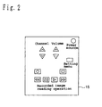
- FIG. 2 shows the configuration of the infrared remote controller according to embodiment 1 of the present invention .
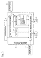
- FIG. 3 is a block diagram of the recording objective determination device 8 according to embodiment 1 of the present invention.
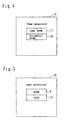
- FIG. 4 shows an example of a screen on which a user is inquired which is to be selected, a user mode or an automatic mode according to embodiment 1 of the present invention.
- FIG. 5 shows an example of a screen on which a user is inquired which is selected, an HDD or a VCR according to embodiment 1 of the present invention.
- FIG. 6 is a block diagram of a recording objective determination device 22 according to an embodiment of the present invention.
- FIG. 7 shows a conventional image recording system.
- FIG. 1 is a block diagram of the data recording and reading system.
- the data recording and reading system according to the first embodiment comprises an antenna 1, a first tuner 2, a data decoding unit 3, a microcontroller 4, memory 5, a second tuner 6, a picture-voice encoding unit 7, a recording objective determination device 8, an HDD 9, a VCR 10, a picture-voice decoding unit 11, a picture-voice graphic switch unit 12, a CRT (Cathode-Ray Tube) 13, a speaker 14, an infrared remote controller 15, and an infrared reception unit 16.
- the antenna 1 is means of receiving an electric wave from a broadcast station, and outputting a signal generated based on the electric wave to the first tuner 2 and the second tuner 6.
- the first tuner 2 outputs all or a part of a digital signal from the antenna 1 to the data decoding unit 3.
- the data decoding unit 3 decodes a digital signal from the first tuner 2, and converts the stored data into a data format to be recorded on the HDD9 and a cassette tape in the VCR10, and to be displayed on the CRT 13 or output as voice from the speaker 14.
- the microcontroller 4 controls the recording objective determination device 8 and the picture-voice graphic switch unit 12 based on the data from the first tuner 2, the memory 5, the recording objective determination device 8, and the infrared reception unit 16.
- the memory 5 records data from the microcontroller 4, and predetermined data.
- the second tuner 6 outputs all or a part of an analog signal from the antenna 1 to the picture-voice encoding unit 7 , and the picture-voice encoding unit 7 can convert an analog signal from the second tuner 6 into a digital signal which can be recorded on the HDD 9 and the cassette tape in the VCR 10.
- the recording objective determination device 8 determines whether image data is to be recorded on the HDD 9 or the VCR 10 .
- the configuration of the recording objective determination device 8 will be described later.
- the HDD 9 stores image data, and contains a hard disk as a fixed type recording medium.
- the VCR 10 is a recording device for recording image data on a cassette tape as a removable recording medium.
- the picture-voice decoding unit 11 converts a signal from the recording objective determination device 8 into a data which can be displayed on the CRT 13 and/or output as voice from the speaker 14.
- the picture-voice graphic switch unit 12 divides received data into image data and voice data, and outputs the image data to the CRT 13, and the voice data to the speaker 14.
- the CRT 13 displays received image data as an image.
- the speaker 14 outputs received voice data as voice.
- the infrared remote controller 15 has a configuration as shown in FIG. 2. A user uses the infrared remote controller 15 when performing operations such as selecting a channel, adjusting the volume of voice, recording and reading data, etc. on a remote site.
- the infrared remote controller 15 outputs an instruction of the user as infrared light.
- the infrared reception unit 16 receives infrared light from the infrared remote controller 15, and outputs the contents of a received signal to the microcontroller 4.
- FIG. 3 is a block diagram of the recording objective determination device 8.
- the recording objective determination device 8 has a user mode 17 and an automatic mode 18, and comprises a mode selection reception means 19, recording objective determination means 20, and a recording and reading control means 21.
- the user mode 17 a user can determine the HDD 9 or the VCR 10 as a recording device for storing image data each time data is to be stored.
- the automatic mode 18 the user does not determine a recording device each time data is to be stored. That is, when a cassette tape is mounted on the VCR 10, the VCR 10 is automatically selected as a recording device for storing image data. When no cassette tape is mounted on the VCR 10, the HDD 9 is automatically selected as a recording device for storing image data.
- the mode selection reception means 19 accepts a selection of a mode, that is, the user mode 17 or the automatic mode 18.
- the recording objective determination means 20 automatically determines the VCR 10 as a recording device for recording image data if a cassette tape is mounted on the VCR 10, and automatically determines the HDD 9 as a recording device for storing image data if no cassette tape is mounted on the VCR 10.
- the recording and reading control means 21 When the mode selection reception means 19 accepts the user mode 17 as a user selection, the recording and reading control means 21 records image data in a user-specified recording device. When the mode selection reception means 19 accepts the automatic mode 18 as a user selection, a recording device determined by the recording objective determination means 20 records image data .
- the recording and reading control means 21 has the function of checking whether or not a cassette tape is mounted on the VCR 10.
- the user selects a program to be displayed on the CRT 13 using the infrared remote controller 15. Then, the infrared remote controller 15 outputs a user instruction as infrared light, and the infrared reception unit 16 receives the infrared light from the infrared remote controller 15, and outputs the contents of the received signal to the microcontroller 4. Then, the microcontroller 4 outputs the contents of the signal from the infrared reception unit 16 to the first tuner 2 and the second tuner 6.
- the first tuner 2 When the program selected by the user is a program formed by digital signals, the first tuner 2 outputs the digital signal of the user-selected program in the digital signals from the antenna 1 to the data decoding unit 3.
- the data decoding unit 3 decodes the digital signal from the first tuner 2, and converts it into data which can be displayed on the CRT 13 or output as voice from the speaker 14.
- the data converted by the data decoding unit 3 is input to the picture-voice graphic switch unit 12 through the microcontroller 4, and the picture-voice graphic switch unit 12 divides input data into image data and voice data, and outputs the image data to the CRT 13, and the voice data to the speaker 14 .
- the program selected by the user is displayed on the CRT 13 in real time, and output as voice from the speaker 14.
- the second tuner 6 outputs the data of the program selected by the user in the analog signals from the antenna 1 to the picture-voice graphic switch unit 12. Then, the picture-voice graphic switch unit 12 divides the input data into image data and voice data, and outputs the image data to the CRT 13 and the voice data to the speaker 14. Thus, the program selected by the user is displayed on the CRT 13 in real time, and output as voice through the speaker 14.
- the user When the user is recording a program to be broadcast by the broadcast station, he or she issues a record instruction using an infrared remote controller 15. Practically, the user presses a 'setting menu' button of the infrared remote controller 15. Then, the infrared remote controller 15 outputs the record instruction from the user using infrared light, and the infrared reception unit 16 receives the infrared light from the infrared remote controller 15, and outputs the contents of the received signal to the microcontroller 4. Then, themicrocontroller 4 outputs the record instruction from the infrared reception unit 16 to the recording objective determination device 8.
- the mode selection reception means 19 When the mode selection reception means 19 receives the record instruction from the microcontroller 4 in the recording objective determination device 8 , the mode selection reception means 19 outputs to the picture-voice decoding unit 11 the contents on the screen for inquiry to the user which the user selects, the user mode 17 in which the user determines a recording device for recording images or the automatic mode 18 in which the user does not determine a recording device, but a recording device for recording images is automatically determined in a predetermined method.
- the picture-voice decoding unit 11 inputs the 'contents on the screen for inquiry to the user' from the mode selection reception means 19, decodes the contents, and outputs the result to the picture-voice graphic switch unit 12.
- the picture-voice graphic switch unit 12 outputs the data from the picture-voice decoding unit 11 to the CRT 13.
- the CRT 13 displays the 'screen for inquiry to the user'.
- FIG. 4 shows an example of the screen for inquiry to the user which mode the user is selecting, the user mode 17 or the automatic mode 18.
- the user selects the user mode 17 or the automatic mode 18 shown in FIG. 4 using the infrared remote controller 15.
- the infrared remote controller 15 outputs the user-selected automatic mode 18 using infrared light.
- the selection of the automatic mode 18 is accepted by the mode selection reception means 19 of the recording objective determination device 8 through the infrared reception unit 16 and the microcontroller 4.
- the recording and reading control means 21 checks whether or not a cassette tape is mounted on the VCR 10, and outputs the check result to the recording obj ective determination means 20 .
- the recording objective determination means 20 determines the VCR 10 as a recording device for recording image data so that a program from a broadcast station can be recorded on the cassette tape mounted on the VCR 10.
- the program data from the broadcast station is input to the recording objective determination device 8 from the first tuner 2 or the second tuner 6 through the data decoding unit 3 and the microcontroller 4, or the picture-voice encoding unit 7 as in the case of displaying the data on the CRT 13 in real time. Then the data is recorded on the cassette tape mounted on the VCR 10 through the recording and reading control means 21 of the recording objective determination device 8.
- the recording objective determination means 20 determines the VCR 10 as a recording device for recording image data so that the program from the broadcast station can be recorded on the HDD 9. Then, the recording and reading control means 21 inputs data to be recorded as in the case of a cassette tape mounted on the VCR 10, and records the data on the HDD 9.
- the recording and reading control means 21 When a cassette tape is mounted on the VCR 10 after the image data has been recorded on the HDD 9, or during the recording of the image data on the HDD 9, the recording and reading control means 21 reads the image data recorded on the HDD 9, and records it again on the cassette tape mounted on the VCR 10. Thus, when the cassette tape is mounted on the VCR 10, the recording and reading control means 21 controls the data recorded on the HDD 9 to be automatically recorded again on the cassette tape mounted on the VCR 10 . Therefore, the user is not required to retrieve the image data recorded on the HDD 9 and to copy the data again on the cassette tape mounted on the VCR 10.
- Another method of the recording and reading control means 21 recording again the data temporarily recorded on the HDD 9 on the cassette tape mounted on the VCR 10 is to sequentially record all data input by the recording and reading control means 21 temporarily on the HDD 9, to allow the HDD 9 to read data in time sharing parallel to the recording operation, to sequentially read the data recorded on the HDD 9, and to record the program data on the cassette tape from the start.
- a further method is to record all program data on the HDD 9, read the data, and record it on a cassette tape from the start of the program data.
- the recording and reading control means 21 records on the cassette tape, not on the HDD 9, the data input after mounting the tape, reads the data recorded on the HDD 9 after a program ends, records it on the cassette tape, and edits the program data such that it can be recorded on the cassette tape in order from the beginning.
- the user selects the automatic mode 18 from between the user mode 17 and the automatic mode 18 shown in FIG. 4 when a program is to be recorded.
- the selection information is accepted by the mode selection reception means 19 of the recording objective determination device 8 as in case of selecting the automatic mode 18.
- the mode selection reception means 19 When the mode selection reception means 19 receives the selection of the user mode 17, the mode selection reception means 19 outputs to the picture-voice decoding unit 11 the contents on the screen for inquiry to the user which is to be selected, the HDD 9 or the VCR 10, as a recording device for recording data. The process is performed as in the case of inquiring the user which is to be used, the user mode 17 or the automatic mode 18.
- the CRT 13 displays a 'screen for inquiry to the user which is to be selected, the HDD 9 or the VCR 10'.
- FIG. 5 shows an example of a screen for inquiry to the user which is to be selected, the HDD 9 or the VCR 10. Assuming that the user has selected the VCR 10, the selection is accepted by the mode selection reception means 19 of the recording objective determination device 8 through the infrared remote controller 15, the infrared reception unit 16, and the microcontroller 4, and the program is recorded on the cassette tape in the VCR 10.
- the selection is similarly accepted by the mode selection reception means 19, and the program is recorded on the HDD 9.
- the infrared remote controller 15 When the user is reading a program recorded on the cassette tape or the HDD 9, he or she issues a read instruction using the infrared remote controller 15. Then, the infrared remote controller 15 outputs a read instruction of the user using the infrared light, and the infrared reception unit 16 receives the infrared light from the infrared remote controller 15, and outputs the contents of a received signal to the microcontroller 4. Then, the microcontroller 4 outputs a read instruction from the infrared reception unit 16 to the recording objective determination device 8.
- the recording and reading control means 21 When the recording and reading control means 21 receives a read instruction from the microcontroller 4 in the recording objective determination device 8, the recording and reading control means 21 reads the cassette tape mounted on the VCR 10 or the HDD 9, and the read signal is output to the picture-voice decoding unit 11.
- the picture-voice decoding unit 11 converts a signal from the recording and reading control means 21 of the recording objective determination device 8 into the data which can be displayed on the CRT 13, or output as voice through the speaker 14, and outputs the result to the picture-voice graphic switch unit 12.
- the picture-voice graphic switch unit 12 divides the data input from the picture-voice decoding unit 11 into image data and voice data, and outputs the image data to the CRT 13, and the voice data to the speaker 14.
- the CRT 13 displays a read picture
- the speaker 14 outputs read voice .
- the HDD 9 and the VCR 10 are used as recording devices.
- the recording device is not limited to the HDD 9 and the VCR 10. It can be any recording device so far as there are a plurality of or any number of recording devices.
- all recording devices can be HDDs and VCRs. It is not necessary to store the plurality of recording devices in one case, and the recording devices can be connected through a transmission network predetermined by the IEEE1394, etc., or through a global network such as Internet.
- the data recording system according to the present invention is configured by the HDD 9 , the VCR 10, and the recording objective determination device 8 according to the embodiment 1 described above.
- a cassette tape is used as a removable recording medium.
- the removable recording medium can be other media such as an optical disk, a magnetic disk, etc.
- the HDD 9 is used as a recording device for recording data on a fixed type recording medium.
- a recording device for recording data on a fixed type recording medium is not limited to the HDD 9.
- the recording objective determination device 8 has the user mode 17 and the automatic mode 18. However, the recording objective determination device 8 can have only the automatic mode 18. In this case, when a user issues a record instruction, the recording objective determination device 8 automatically determines as a recording device a cassette tape if it is mounted on the VCR 10, and the HDD 9 if no cassette tape is mounted on the VCR 10.
- the recording objective determination device 8 determines a recording device depending on whether or not a cassette tape is mounted on the VCR 10. However, regardless of whether or not a cassette tape is mounted on the VCR 10, the VCR 10 or the HDD 9 can be determined as a recording objective. In this case, if the VCR 10 is determined as a recording device, and no cassette tape is mounted on the VCR 10, then data is not recorded although the user has issued a record instruction.
- the recording and reading control means 21 of the recording objective determination device 8 has the function of checking whether or not a cassette tape has been mounted on the VCR 10, but the means for checking whether or not a cassette tape has been mounted on the VCR 10 can be provided independently of the recording and reading control means 21.
- the recording objective determination device 8 determines a recording device depending on whether or not a cassette tape has been mounted on the VCR 10.
- a predetermined recording device can be automatically determined as a recording objective for recording data when the user has issued a record instruction.
- a user-predetermined recording device can be the VCR 10 or the HDD 9.
- the recording objective determination device 8 can determine a recording device for recording data when a user reserves a recording process, or when the recording process actually starts. If the user is recording data in real time, the recording device for recording data is determined when the recording process is performed.
- the recording obj ective determination device 8 can be replaced with the recording objective determination device 22 shown in FIG. 6.
- the recording objective determination device 22 has the user mode 17 and the automatic mode 18, and comprises the mode selection reception means 19, recording objective determination means 23, recording and reading control means 24, and use frequency check means 25.
- the use frequency check means 25 checks which has been used more frequently as a recording device, the HDD 9 or the VCR 10, and the recording objective determination means 23 determines a recording device which has been used more frequently as a recording device for recording data. For example, when the user prefers the HDD 9, the use frequency of the HDD 9 is higher than the use frequency of the VCR 10. Therefore, the recording objective determination means 23 determines the HDD 9 as a recording device for recording data.
- the recording and reading control means 24 of the recording objective determination device 22 shown in FIG. 6 has the function obtained by subtracting the function of checking whether or not a cassette tape has been mounted on the VCR 10 from the function of the recording and reading control means 21 in the recording objective determination device 8 shown in FIG. 3.
- the user mode 17, the automatic mode 18, and the mode selection reception means 19 are the same as the corresponding functions in the recording obj ective determination device 8.
- the recording objective determinationdevice 8 determines a recording device depending on whether or not a cassette tape has been mounted on the VCR 10. However, although a cassette tape has been mounted on the VCR 10, the recording objective determination device 8 does not determine the VCR 10 as a recording device for recording data if the remaining recording capacity of the cassette tape is equal to or smaller than a predetermined capacity, or it is prohibited to newly record data on the cassette tape.
- a method of re-recording the copied data that is, the data temporarily recorded on the HDD 9, on the cassette tape newly mounted on the VCR 10 can be the above mentioned method of re-recording data on a cassette tape when no cassette tape is mounted on the VCR 10, and a cassette tape is mounted on the VCR 10 after data has been recorded on the HDD 9, or during data is being recorded on the HDD 9.
- the HDD 9 can be set not to record data if the remaining recording capacity of the HDD 9 is equal to or smaller than a predetermined capacity or it is prohibited to newly record data on the HDD 9. In this case, it is recommended that the user is notified of the information.
- the present invention is a program for causing a computer to perform the function of all or a part of the means of the above-mentioned the recording objective determination device of the present invention, and hence a program working in cooperation with the computer.
- a part of the means of the present invention indicates either a certain number of pieces of the plural pieces of the means thereof or a part of the function of a piece of means.
- a computer readable recording medium having recorded a program of the present invention is included within the scope of the present invention.
- the program may be recorded on a computer readable recording medium thereby to work in cooperation with a computer.
- the program may be transferred through a transferring medium, and read by a computer thereby to work in cooperation with the computer.
- the media include a ROM, while the transferring media include a transferring medium such as the Internet, light, radio waves, and sound waves.
- the computer of the present invention is not limited pure hardware such as CPU or the like, and it may include firmware, operating system, I/O devices and peripheral devices.
- the configuration of the present invention may be implemented by a software or a hardware.
- the present invention can provide a recording objective determination device for automatically determine a recording device for recording data in a predetermined method without having a user determine it each time data is to be recorded, and a data recording system comprising the recording objective determination device and a plurality of recording devices.
Landscapes
- Engineering & Computer Science (AREA)
- Multimedia (AREA)
- Signal Processing (AREA)
- Signal Processing For Digital Recording And Reproducing (AREA)
- Television Signal Processing For Recording (AREA)
- Management Or Editing Of Information On Record Carriers (AREA)
- Testing, Inspecting, Measuring Of Stereoscopic Televisions And Televisions (AREA)
Applications Claiming Priority (2)
| Application Number | Priority Date | Filing Date | Title |
|---|---|---|---|
| JP2000133205A JP2001319419A (ja) | 2000-05-02 | 2000-05-02 | データ記録システム、記録先決定装置、媒体、および情報集合体 |
| JP2000133205 | 2000-05-02 |
Publications (2)
| Publication Number | Publication Date |
|---|---|
| EP1152608A2 true EP1152608A2 (de) | 2001-11-07 |
| EP1152608A3 EP1152608A3 (de) | 2005-06-08 |
Family
ID=18641746
Family Applications (1)
| Application Number | Title | Priority Date | Filing Date |
|---|---|---|---|
| EP01110695A Ceased EP1152608A3 (de) | 2000-05-02 | 2001-05-02 | Datenaufnahmesystem und Vorrichtung zur Aufnahmeobjektbestimmung |
Country Status (6)
| Country | Link |
|---|---|
| US (1) | US7164843B2 (de) |
| EP (1) | EP1152608A3 (de) |
| JP (1) | JP2001319419A (de) |
| KR (1) | KR100689555B1 (de) |
| CN (1) | CN1322103A (de) |
| MY (1) | MY131862A (de) |
Cited By (2)
| Publication number | Priority date | Publication date | Assignee | Title |
|---|---|---|---|---|
| EP1603334A4 (de) * | 2002-11-19 | 2009-06-03 | Nec Corp | Videoprüfsystem und verfahren |
| EP1701350A3 (de) * | 2005-03-11 | 2011-06-29 | Yamaha Corporation | Vorrichtung zur Inhaltsdatenaufzeichnung mit Verschlüsselung mittels Medien-ID |
Families Citing this family (8)
| Publication number | Priority date | Publication date | Assignee | Title |
|---|---|---|---|---|
| JP2004062916A (ja) | 2002-06-05 | 2004-02-26 | Sony Corp | 情報処理装置および方法、記録媒体、並びにプログラム |
| CN100474910C (zh) * | 2003-05-05 | 2009-04-01 | 汤姆森许可公司 | 用于可控制地记录到一个互联的兼容ieee-1394的装置的方法 |
| US20060291799A1 (en) * | 2003-05-05 | 2006-12-28 | Mears Mark G | Method for tuning to an interconnected ieee-1394 compliant device |
| JP4211541B2 (ja) * | 2003-09-01 | 2009-01-21 | ソニー株式会社 | 記録制御システム、記録予約処理方法 |
| JP2006099853A (ja) * | 2004-09-29 | 2006-04-13 | Hitachi Global Storage Technologies Netherlands Bv | 記録再生装置 |
| US20080310825A1 (en) * | 2007-06-12 | 2008-12-18 | Microsoft Corporation | Record quality based upon network and playback device capabilities |
| JP2009017048A (ja) * | 2007-07-02 | 2009-01-22 | Sony Corp | 録画制御装置及び録画システム |
| US8950147B2 (en) | 2011-08-22 | 2015-02-10 | Awi Licensing Company | Floor panel and floating floor system incorporating the same |
Citations (3)
| Publication number | Priority date | Publication date | Assignee | Title |
|---|---|---|---|---|
| EP0660485A2 (de) * | 1993-12-22 | 1995-06-28 | Canon Kabushiki Kaisha | Elektrisches Gerät |
| JPH10172237A (ja) * | 1996-12-06 | 1998-06-26 | Sanyo Electric Co Ltd | 情報記憶制御方法、情報記憶制御装置、およびその制御機能を有する情報記憶装置 |
| EP0969661A1 (de) * | 1997-03-21 | 2000-01-05 | Hitachi, Ltd. | Audiovisuelles gerät, verfahren und system |
Family Cites Families (11)
| Publication number | Priority date | Publication date | Assignee | Title |
|---|---|---|---|---|
| JPH06150483A (ja) * | 1992-10-31 | 1994-05-31 | Sony Corp | カセツトオートチエンジヤ制御装置 |
| CN1312609C (zh) * | 1995-04-08 | 2007-04-25 | 索尼公司 | 编辑系统 |
| JPH0925915A (ja) | 1995-07-07 | 1997-01-28 | Louis N Giannuzzi | ウォールアンカー |
| JPH09259515A (ja) * | 1996-03-19 | 1997-10-03 | Fujitsu Ltd | Avコントローラ |
| JP3669539B2 (ja) | 1997-03-25 | 2005-07-06 | ソニー株式会社 | 電子機器および電子機器制御方法、情報提供装置および方法、並びに情報提供システム |
| US6678462B1 (en) * | 1997-03-25 | 2004-01-13 | Sony Corporation | Electronic device, method and apparatus for controlling an electronic device, and electronic device control system |
| JPH11205313A (ja) | 1998-01-08 | 1999-07-30 | Toshiba Corp | ネットワーク装置及びネットワーク表示方法 |
| JP3501645B2 (ja) | 1998-02-13 | 2004-03-02 | 富士通株式会社 | 放送映像録画装置 |
| KR100482831B1 (ko) * | 1998-06-19 | 2005-08-29 | 엘지전자 주식회사 | 타임랩스영상녹화재생기에서의녹화영상의유지/기록방법및그장치 |
| JP2000047829A (ja) | 1998-07-29 | 2000-02-18 | Nec Corp | ライブラリ型記憶装置及びそれに用いる記憶方法並びにその制御プログラムを記録した記録媒体 |
| JP2000184320A (ja) * | 1998-12-11 | 2000-06-30 | Nec Corp | 記録再生装置および電子番組ガイド表示装置 |
-
2000
- 2000-05-02 JP JP2000133205A patent/JP2001319419A/ja active Pending
-
2001
- 2001-04-30 CN CN01117269A patent/CN1322103A/zh active Pending
- 2001-04-30 MY MYPI20012031A patent/MY131862A/en unknown
- 2001-05-01 US US09/845,315 patent/US7164843B2/en not_active Expired - Fee Related
- 2001-05-02 KR KR1020010023828A patent/KR100689555B1/ko not_active Expired - Fee Related
- 2001-05-02 EP EP01110695A patent/EP1152608A3/de not_active Ceased
Patent Citations (4)
| Publication number | Priority date | Publication date | Assignee | Title |
|---|---|---|---|---|
| EP0660485A2 (de) * | 1993-12-22 | 1995-06-28 | Canon Kabushiki Kaisha | Elektrisches Gerät |
| JPH10172237A (ja) * | 1996-12-06 | 1998-06-26 | Sanyo Electric Co Ltd | 情報記憶制御方法、情報記憶制御装置、およびその制御機能を有する情報記憶装置 |
| US20010022620A1 (en) * | 1996-12-06 | 2001-09-20 | Mayumi Niwa | Dynamic data storage control method and system |
| EP0969661A1 (de) * | 1997-03-21 | 2000-01-05 | Hitachi, Ltd. | Audiovisuelles gerät, verfahren und system |
Non-Patent Citations (1)
| Title |
|---|
| PATENT ABSTRACTS OF JAPAN * |
Cited By (3)
| Publication number | Priority date | Publication date | Assignee | Title |
|---|---|---|---|---|
| EP1603334A4 (de) * | 2002-11-19 | 2009-06-03 | Nec Corp | Videoprüfsystem und verfahren |
| EP1701350A3 (de) * | 2005-03-11 | 2011-06-29 | Yamaha Corporation | Vorrichtung zur Inhaltsdatenaufzeichnung mit Verschlüsselung mittels Medien-ID |
| US8437618B2 (en) | 2005-03-11 | 2013-05-07 | Yamaha Corporation | Content data recording apparatus with encryption by media ID |
Also Published As
| Publication number | Publication date |
|---|---|
| US7164843B2 (en) | 2007-01-16 |
| CN1322103A (zh) | 2001-11-14 |
| EP1152608A3 (de) | 2005-06-08 |
| KR20010102926A (ko) | 2001-11-17 |
| JP2001319419A (ja) | 2001-11-16 |
| MY131862A (en) | 2007-09-28 |
| US20010041046A1 (en) | 2001-11-15 |
| KR100689555B1 (ko) | 2007-03-09 |
Similar Documents
| Publication | Publication Date | Title |
|---|---|---|
| US8498514B2 (en) | Information processing apparatus, information managing method and medium | |
| US6775085B2 (en) | Apparatus for recording and reproducing information and information reproducing method | |
| US7286744B2 (en) | Apparatus for recording and reproducing information onto and from a recording medium having a ring buffer area | |
| US7164843B2 (en) | Data recording system and recording objective determination device | |
| US7362944B2 (en) | Combination system using set-up value commonly, and method for setting up value of the same | |
| US20090003804A1 (en) | Recording/Reproducing Apparatus, Transmitting Apparatus and Transmitting Method | |
| EP1517270A2 (de) | Vorrichtung, Verfahren, Programm und Programmspeichermedium zur Bearbeitung und Aufzeichnung von Daten | |
| EP2026573A2 (de) | Digitale Inhaltsaufzeichnungsvorrichtung und Dubbing-Verfahren dafür | |
| EP1353328B1 (de) | Vorrichtung zur Wiedergabe eines Aufnahmemediums | |
| US7050704B1 (en) | Method for storing and retrieving digital data to/from a tape recording medium through a digital interface | |
| US20050069284A1 (en) | Apparatus, method and program for recording/reproducing information and information recording medium | |
| JP2009044515A (ja) | 情報処理システム、記録装置、携帯機器、情報処理方法、及びプログラム | |
| EP1850344A1 (de) | Bildanzeigevorrichtung und Programmeditierverfahren | |
| JP2006018871A (ja) | 記録再生装置、ディジタルコンテンツコピー方法 | |
| JP4292506B2 (ja) | 録画システム | |
| JPH07297794A (ja) | 自動インデックス装置及び自動頭出し装置 | |
| EP1638103A1 (de) | Kombinationsaufzeichungsgerät zur automatischen Bestimmung einer Relay-aufzeichnung und Verfahren dazu | |
| EP1775941A2 (de) | Gerät zum Schreiben Einstellungsinformationen und Elektronische Vorrichtung ausgestattet mit Tuner | |
| JP4168996B2 (ja) | コンテンツデータ記録再生システム及びコンテンツデータ記録再生方法 | |
| JP2793070B2 (ja) | タイトル編集機能を持つリモコン | |
| EP1553756A2 (de) | Persönlicher Videorekorder | |
| WO2006016522A1 (ja) | データ処理システム | |
| EP1653460A1 (de) | Kombiniertes Aufnahmegerät mit automatischer Auswahl eines Aufnahmegerätes sowie entsprechendes Verfahren | |
| JP2004326374A (ja) | 処理装置および処理装置と接続されたサーバ | |
| KR20040096694A (ko) | 휴대용 단말기에서 음성을 갖는 영상을 만드는 방법 |
Legal Events
| Date | Code | Title | Description |
|---|---|---|---|
| PUAI | Public reference made under article 153(3) epc to a published international application that has entered the european phase |
Free format text: ORIGINAL CODE: 0009012 |
|
| AK | Designated contracting states |
Kind code of ref document: A2 Designated state(s): AT BE CH CY DE DK ES FI FR GB GR IE IT LI LU MC NL PT SE TR |
|
| AX | Request for extension of the european patent |
Free format text: AL;LT;LV;MK;RO;SI |
|
| PUAL | Search report despatched |
Free format text: ORIGINAL CODE: 0009013 |
|
| AK | Designated contracting states |
Kind code of ref document: A3 Designated state(s): AT BE CH CY DE DK ES FI FR GB GR IE IT LI LU MC NL PT SE TR |
|
| AX | Request for extension of the european patent |
Extension state: AL LT LV MK RO SI |
|
| 17P | Request for examination filed |
Effective date: 20050602 |
|
| AKX | Designation fees paid |
Designated state(s): DE FR GB |
|
| RAP1 | Party data changed (applicant data changed or rights of an application transferred) |
Owner name: PANASONIC CORPORATION |
|
| STAA | Information on the status of an ep patent application or granted ep patent |
Free format text: STATUS: THE APPLICATION HAS BEEN REFUSED |
|
| 18R | Application refused |
Effective date: 20090528 |