EP1153233B1 - Dispositif d'etancheite d'arbre - Google Patents
Dispositif d'etancheite d'arbre Download PDFInfo
- Publication number
- EP1153233B1 EP1153233B1 EP00914089A EP00914089A EP1153233B1 EP 1153233 B1 EP1153233 B1 EP 1153233B1 EP 00914089 A EP00914089 A EP 00914089A EP 00914089 A EP00914089 A EP 00914089A EP 1153233 B1 EP1153233 B1 EP 1153233B1
- Authority
- EP
- European Patent Office
- Prior art keywords
- seal
- sleeve
- pusher
- sealing
- auxiliary
- Prior art date
- Legal status (The legal status is an assumption and is not a legal conclusion. Google has not performed a legal analysis and makes no representation as to the accuracy of the status listed.)
- Expired - Lifetime
Links
- 238000007789 sealing Methods 0.000 claims abstract description 161
- 239000012530 fluid Substances 0.000 claims abstract description 37
- 238000004891 communication Methods 0.000 claims abstract description 4
- 239000007789 gas Substances 0.000 description 14
- 239000000463 material Substances 0.000 description 10
- 230000004048 modification Effects 0.000 description 9
- 238000012986 modification Methods 0.000 description 9
- 238000000926 separation method Methods 0.000 description 9
- 239000011324 bead Substances 0.000 description 7
- 238000013461 design Methods 0.000 description 7
- 230000000694 effects Effects 0.000 description 6
- 238000010276 construction Methods 0.000 description 4
- 230000009471 action Effects 0.000 description 3
- 230000008901 benefit Effects 0.000 description 3
- 230000006835 compression Effects 0.000 description 2
- 238000007906 compression Methods 0.000 description 2
- 238000005461 lubrication Methods 0.000 description 2
- VNWKTOKETHGBQD-UHFFFAOYSA-N methane Chemical compound C VNWKTOKETHGBQD-UHFFFAOYSA-N 0.000 description 2
- 230000009467 reduction Effects 0.000 description 2
- 238000013022 venting Methods 0.000 description 2
- OKTJSMMVPCPJKN-UHFFFAOYSA-N Carbon Chemical compound [C] OKTJSMMVPCPJKN-UHFFFAOYSA-N 0.000 description 1
- 239000003570 air Substances 0.000 description 1
- 230000005540 biological transmission Effects 0.000 description 1
- 229910052799 carbon Inorganic materials 0.000 description 1
- 230000008859 change Effects 0.000 description 1
- 230000007423 decrease Effects 0.000 description 1
- 230000001419 dependent effect Effects 0.000 description 1
- 238000006073 displacement reaction Methods 0.000 description 1
- 238000005516 engineering process Methods 0.000 description 1
- 238000001125 extrusion Methods 0.000 description 1
- 230000020169 heat generation Effects 0.000 description 1
- 229910052739 hydrogen Inorganic materials 0.000 description 1
- 239000001257 hydrogen Substances 0.000 description 1
- 125000004435 hydrogen atom Chemical class [H]* 0.000 description 1
- 239000002184 metal Substances 0.000 description 1
- 239000003345 natural gas Substances 0.000 description 1
- 229920000642 polymer Polymers 0.000 description 1
- 230000000750 progressive effect Effects 0.000 description 1
Images






Classifications
-
- F—MECHANICAL ENGINEERING; LIGHTING; HEATING; WEAPONS; BLASTING
- F16—ENGINEERING ELEMENTS AND UNITS; GENERAL MEASURES FOR PRODUCING AND MAINTAINING EFFECTIVE FUNCTIONING OF MACHINES OR INSTALLATIONS; THERMAL INSULATION IN GENERAL
- F16J—PISTONS; CYLINDERS; SEALINGS
- F16J15/00—Sealings
- F16J15/16—Sealings between relatively-moving surfaces
- F16J15/34—Sealings between relatively-moving surfaces with slip-ring pressed against a more or less radial face on one member
- F16J15/3464—Mounting of the seal
Definitions
- the invention relates to a shaft seal for rotating shafts in turbo-machines or other pressurized machine.
- the present invention in common with WO-A-96/33357 provides a shaft seal comprising a sealing element, a rotary sealing part mounted coaxially with the sealing element and forming therewith a contactless primary seal between opposed faces of the sealing element and rotary sealing part to substantially prevent fluid flow across the primary seal from a high pressure radial side to a low-pressure radial side, a seal housing, a pusher sleeve disposed, between the seal housing and the sealing element, coaxially with and in contact with the sealing element, biasing means urging the pusher sleeve away from the seal housing and against the sealing element to urge the sealing element axially towards the rotary sealing part, and a first sealing member disposed about the pusher sleeve and located, in a channel, in communication with the high-pressure radial side to provide a secondary seal for the pusher sleeve between the high-pressure and
- Non-contacting shaft seals are often used with machinery for the compression or expansion of gas (hydrogen, natural gas, air, etc.) where the transmission of gas along the shaft needs to be prevented. Due to the high-pressure, high-speed machinery which is normally used, the shaft seals are chosen to be of non-contact type, in order to reduce heat build up in the seals and the wear of the sealing parts and/or in order to avoid the complexity of oil seals and their associated systems.
- Non-contacting operation avoids this undesirable face contact when the shaft is rotating above a certain minimum speed, which is often called a lift-off speed.
- Non-contacting shaft seals provide advantages over seals where the sealing surfaces contact one another, due to reduction in wear and the lower heat generation.
- Articles entitled “Fundamentals of Spiral Groove Non-contacting Face Seals” by Gabriel, Ralph P. (Journal of American Society of Lubrication Engineers Volume 35, 7, pages 367-375), and “Improved Performance of Film-Riding Gas Seals Through Enhancement of Hydrodynamic Effects” by Sedy, Joseph (Transaction of the American Society of Lubrication Engineers, Volume 23, 1 pages 35-44) describe non-contacting seal technology and design criteria and are incorporated herein by reference.
- a non-contacting face seal consists of two principal sealing elements. At least one of the sealing elements is provided with shallow surface recesses.
- both sealing elements in the form of rings, are positioned adjacent to each other with the sealing surfaces in contact at conditions of zero pressure differential and zero speed of rotation.
- One of the rings is normally fixed to the rotatable shaft by means of a shaft sleeve, the other being located within the seal housing structure and allowed to move axially.
- the shaft seal is designed to enable axial movement of the sealing ring and yet prevent or substantially minimize leakage of the sealed fluid. For this reason, a sealing member is placed between the ring and the housing.
- one of the two sealing surfaces is provided with shallow surface recesses, which act to generate pressure fields that force the two sealing surfaces apart. when the magnitude of the forces resulting from these pressure fields is large enough to overcome the forces that urge the seal faces closed, the sealing surfaces will separate and form a clearance, resulting in non-contacting operation.
- the character of the separation forces is such that their magnitude decreases with the increase of face separation.
- Opposing or closing forces depend on sealed pressure level and as such are independent of face separation. They result from the sealed pressure and the spring force acting on the back surface of the axially movable sealing ring. Since the separation or opening force depends on the separation distance between sealing surfaces, during the operation of the seal or on imposition of sufficient pressure, differential equilibrium separation between both surfaces will establish itself. This occurs when closing and opening forces are in equilibrium and equal to each other. Equilibrium separation constantly changes within the range of gaps. The goal is to have the low limit of this range above zero.
- Fig. 1 is a partial longitudinal sectional view through the shaft seal showing the relevant structural elements of a non-contacting shaft seal of the type described above.
- the shaft seal is incorporated in a turbo-machine (not shown), such as a compressor in this example.
- a shaft seal 1 having a (non-rotating) sealing element or ring 2 mounted coaxially with the shaft axis (denoted by reference numeral 3), and a rotary sealing part or ring 4 located coaxially with the sealing ring 2, and therefore also with the shaft axis 3.
- the vertical sectional view of Figure 1 shows only the portion of the shaft seal located above the shaft axis.
- the sealing ring 4 is mounted on an inner sleeve 5 having a radial flange 5a against which the sealing ring 4 abuts, the sleeve 5 being mounted on the shaft 6 such that the shaft 6, inner sleeve 5 and rotary sealing ring 4 co-rotate as a single rotary element.
- a locating sleeve 7 is bolted to inner sleeve 5. The assembly comprising components 4, 5 and 7 is prevented from displacement in one axial direction by a locating ring 21 and in the opposite axial direction by the high pressure acting inside the compressor.
- the shaft seal also has a seal housing 8 and a pusher sleeve 9 disposed between a radially inward flange 8b of the seal housing 8 and sealing ring 2.
- the pusher sleeve has a radial flange 9b against which a plurality of biasing springs (one of which, 10, is shown in Figure 1,) located at the same axial position in respective blind holes 11 in radially inward flange 8b and distributed about the shaft axis, act to urge the pusher sleeve 9 against the sealing ring 2.
- the (non-rotary) sealing ring 2 and rotary sealing ring 4 together form a contactless primary seal when the turbo-machine (or pressurized machine) is in operation, which substantially prevents fluid flow between the sealing faces of the primary seal, from the high pressure radially outer side to the low pressure radially inner side.
- the sealing face of sealing ring 2 has shallow grooves cut into its front surface to generate the required separation between the sealing faces of sealing rings 2, 4. Alternatively, the grooves could be formed in the rotary sealing ring 4.
- the sealing element 2 is normally made from carbon or other suitable material.
- the sealing element 2 is afforded limited axial movement against the biasing force of the springs 10.
- These springs provide a relatively small net biasing force so that when the shaft is rotating at normal speed, the generated separating forces cause the sealing ring 4 to separate from the sealing ring 2.
- the gap between these rings adjusts itself such that the generated opening forces on the one hand and the sum of the generated closing forces and the spring biasing force on the other hand are equal to one another.
- the springs act to move the sealing ring 2 into contact with the rotary sealing ring 4.
- a high-pressure gas is supplied to the radially outer edge of the seal rings 2, 4. Normally, this gas would be derived from the working fluid of the machine. However, it could instead be a clean gas suitable for venting into the atmosphere. In that event, the vented gas can be a combustible gas which is piped to burn (flare).
- the high pressure at the high-pressure radial side acts around the rear face of sealing element 2 down to a so-called equilibrium balance diameter.
- Secondary seals 12, 13 are provided to prevent the high pressure venting around the rear face of sealing element 2 to the low-pressure radial side (atmospheric pressure).
- the balance diameter is determined essentially by the contact line of secondary seal 12 with the housing 8.
- the first secondary seal 12 is provided between the pusher sleeve 9 and the radially inward flange 8b of the seal housing 8.
- This seal can be of any suitable form, such as a conventional O-ring, or, as shown, a spring-energised U-seal. Other forms of seal are possible and the precise form selected is not material.
- the first secondary seal 12, as shown in Figures 1, 1a, is located in a channel 14 formed in the main axially-extending sleeve portion 9a of the pusher sleeve 9. This secondary seal presses sealingly against the bottom of the channel 14 formed in the main axially-extending sleeve portion 9a. It also presses sealingly against the axially-extending inner radial face of the radially inward flange 8b, thereby defining the equilibrium balance diameter for the shaft seal when operating in its equilibrium mode.
- the further secondary seal 13 is provided between the rear face of sealing ring 2 and the radial flange 9b of pusher sleeve 9.
- this secondary seal can take the form of an O-ring or, as shown, a spring-energised U-seal or Y-seal.
- the secondary seal 13 is located in a channel 15 formed in pusher sleeve 9. Alternatively, the channel 15 could be formed in sealing element 2.
- the high-pressure working fluid of the compressor is admitted to the high-pressure radial side of the primary seal.
- This pressure acts on an outer annular region of the front face of the radial flange 9a of pusher sleeve 9, the outer annular region having an inner diameter defined by the line of sealing of the secondary seal 13 against the sealing ring 2 and the radially outer diameter of radial flange 9a.
- the high-pressure fluid also acts against the rear face of pusher sleeve 9 and down to the balance diameter.
- the secondary seals 12, 13 seal the applied high-pressure from the low-pressure radial side, which is at atmospheric pressure where a single shaft seal is used or, if multiple shaft seals are provided in cascade, at a lower pressure than the pressure to be sealed. Because of the pressure differential acting on the area of the rear face of radial flange 9a from the sealing diameter of the seal 13 down to the balance diameter, there is a net closing force (to the left in Figure 1) acting on the pusher sleeve 9, against the sealing ring 2 at all times. This closing force is supplemented by the action of the biasing springs 10, and these closing forces are applied in the closing direction against sealing ring 2.
- the high pressure fluid acting on the front faces of sealing ring 2 produces an opening force
- the high pressure fluid acting on the rear faces down to the sealing diameter of secondary seal 13 produces a closing force
- the taper-shaped surface recesses or grooves cut in the front face of sealing ring 2 (or rear, face of sealing ring 4) generate separating pressure fields acting between the sealing rings 2, 4, the magnitude of the pressure fields depending on the rotational speed of the compressor shaft.
- the high pressure to be sealed, the depths of the recesses or grooves and the size of the gap between the sealing rings 2, 4 also influence the magnitude of the pressure fields. Whether the sealing rings 2, 4 of the shaft seal are in contact or separated depends on the magnitudes of the generated opening and closing forces, and the net spring biasing force.
- the primary seal When the compressor is started up, as the rotational speed of the shaft 6 initially starts to build up, the primary seal maintains a substantially fluid-tight seal between the high-pressure and low-pressure radial sides, by virtue of sealing contact between the sealing rings 2, 4. Under these conditions, the net separating force generated by the primary seal is insufficient to overcome the sum of the spring biasing forces and the net closing force acting on the primary seal due to the applied high-pressure.
- the channel 14 instead of being formed in the pusher sleeve 9, is formed in the seal housing 8.
- Such arrangements are disclosed in EP-A-0591586 of Nippon Pillar Packing Co. Ltd. and US-A-5421593 belonging to the same. proprietor.
- Shaft seals of the type described above with reference to Figures 1 and 2 operate satisfactorily at typical sealing pressures of compressors that have been manufactured in the past.
- compressors typically have been manufactured for compressing gases at pressures of typically from about 200 bar to about 500 bar.
- the industry is now demanding compressors to compress gas from 300 bar or more to 800 bar or more.
- existing shaft seal designs are not adequate to withstand such inlet-pressure values, for the reasons now to be described with reference to Figures 1a and 2a.
- the bead 12b continues to grow, an increasingly unstable situation can develop whereby the sealing ability of the secondary seal 12 is progressively lessened due to the continuing extrusion, until eventually an unstable situation is reached in which the seal 12 is expelled or blown out through the gap, resulting in failure of the shaft seal. It is noted that the bead 12b does not normally form around the entire rear circumferential region of the secondary seal 12 but generally only at a single angular position about the seal circumference.
- Another potential solution which has been considered is to use harder materials for forming the sealing parts of the secondary seal 12, or to use back-up rings of harder material than the sealing parts themselves of the secondary seal.
- harder materials for forming the sealing parts of the secondary seal 12, or to use back-up rings of harder material than the sealing parts themselves of the secondary seal.
- harder materials are less effective to provide the required sealing effect and they also increase the friction forces generated.
- the present invention seeks to provide a shaft seal which is improved in the above respects and can withstand high operating pressures, in the range from zero bar to 300 bar or more. It relates to a shaft seal as initially defined and is characterised by an auxiliary sleeve disposed around the pusher sleeve coaxially therewith and maintained in sealing contact with the pusher sleeve by the first sealing member, the auxiliary sleeve being arranged to be urged in an axial direction by fluid pressure acting at the high pressure radial side to form a tertiary seal.
- the function of the tertiary seal is merely to maintain sealing contact between the seal housing and auxiliary sleeve.
- the geometry, material and design of the auxiliary sleeve is such that the distortion of the auxiliary sleeve substantially matches that of the pusher sleeve under fluid pressure, so that the gap between these two elements remains substantially the same irrespective of the fluid pressure acting, thereby avoiding or minimising the risk of a bead forming on the first sealing member.
- said channel in which said first sealing member is located is formed in the pusher sleeve. This maximises the closing force acting on the pusher sleeve when operating under high fluid pressure, because then the seal provided by the first sealing member against the pusher sleeve is located at a radially inward location.
- said channel in which said first sealing member is located may be formed in the auxiliary sleeve.
- the biasing means acts between the pusher sleeve and the auxiliary sleeve.
- This arrangement guarantees that the sealing effect of the tertiary seal is kept integral at all times, so that when the fluid pressure is applied it is prevented from passing unrestrictedly past the auxiliary sleeve to the low-pressure radial side.
- the biasing means it is alternatively possible for the biasing means to act between the seal housing and the pusher sleeve, because it is considered that when the high fluid pressure is applied at the high-pressure radial side, the auxiliary sleeve will, as a result of the location of the tertiary seal, be urged in the axial direction, ensuring that the tertiary seal performs its required sealing function.
- the tertiary seal is provided by face-to-face contact between transverse faces of the auxiliary sleeve and seal housing, when the shaft seal is in use.
- a separate tertiary seal is provided, for greater sealing integrity.
- the tertiary seal comprises an O-ring located in a channel formed in the transverse end face of the auxiliary sleeve.
- the tertiary seal comprises an O-ring located in a channel formed in the transverse end face of the seal housing.
- it can comprise a spring-energised U-seal or Y-seal.
- the pusher sleeve will comprise a main axially-extending portion with a radial flange at one end in contact face-to-face with the sealing element.
- This design for the pusher sleeve is preferred because then the main axially-extending portion can serve to provide for accommodating the required limited axial movement of the pusher sleeve while the first sealing member maintains sealing contact with the auxiliary sleeve, and the radial flange conveniently serves to receive the bias force of the biasing means and apply it against the sealing element.
- the flange substantially resists radially inward distortion of the pusher sleeve at the one axial end of the pusher sleeve.
- the auxiliary sleeve preferably similarly comprises a main axially-extending portion with a radial flange at one end facing the flange of the pusher sleeve. This arrangement for the auxiliary sleeve helps to ensure that its distortion under pressure closely conforms with that of the pusher sleeve.
- the pusher sleeve is of the same construction, but the auxiliary sleeve is in the form of a sleeve over its entire length. Then, when the shaft seal is in use, the high fluid pressure acting on the outside of the low-pressure axial end portion of the auxiliary seal beyond the sealing location of the first sealing member will deflect that end portion inwardly, again reducing the likelihood of the first sealing member being blown out of the shaft seal.
- a further secondary seal may be provided between adjacent radial surfaces of said sealing ring and said pusher sleeve.
- the tertiary seal can be provided by a lip formed integrally on and protruding from one of said seal housing and said auxiliary sleeve, said lip sealingly contacting the other of said seal housing and said auxiliary sleeve.
- said secondary seal between said sealing ring and said pusher sleeve may be provided by a lip formed integrally on and protruding from one of said pusher sleeve and said sealing ring, said lip being maintained sealingly in contact with the other of said pusher element and said sealing ring.
- the pusher sleeve comprises an inner pusher sleeve element and an outer annular pusher disc, the inner pusher sleeve element and the outer pusher disc having respective radial surfaces maintained in contact with one another.
- the auxiliary sleeve comprises an inner auxiliary sleeve element and an outer annular auxiliary disc, the inner auxiliary sleeve element and the outer annular auxiliary disc having respective radial surfaces maintained in contact with one another.
- the shaft seal may be incorporated in a turbo-machine or other pressurized machine, though for convenience the description which follows relates to the specific case of a compressor, as in the prior art examples described with reference to Figures 1, 1a and 2, 2a.
- the shaft seal 1 additionally comprises an auxiliary sleeve 20 disposed around the pusher sleeve 9 co-axially therewith, with a small gap radially separating the two sleeves 9, 20 and located within a recess 17 within the radially inner flange 8b.
- the auxiliary sleeve comprises a main axially-extending sleeve portion 20a having at one end a radial flange 20b facing the rear face of the radial flange 9b of the pusher sleeve 9.
- a tertiary seal 16 provides a substantially fluid-type seal between the transverse rear-facing end face of the sleeve portion 20a and an adjacent forwardly-facing, transverse annular face 19 of the seal housing. As shown, this seal is preferably in the form of a spring energised Y-seal.
- the first secondary sealing member 12 provides a substantially fluid-tight seal between the auxiliary sleeve and the pusher sleeve 9.
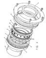
- Figure 4 is an exploded view of the shaft seal, giving a clear indication of the geometry of the respective elements of the shaft seal.
- This Figure also shows the modification in which the taper shaped grooves are formed in the sealing face of rotary sealing ring 4, rather than of the non-rotating sealing ring 2.
- the high pressure fluid acting at the high-pressure fluid side of the primary seal acts, just as in the case of the known shaft seals according to Figures 1, 1a and 2, 2a, against the pusher sleeve 9 to cause the axially-extending sleeve portion to deflect radially inwardly.
- the distortion of the axially extending sleeve portion is progressive from the axial location of secondary seal 12 along the length of the pusher sleeve, because of the pressure differential between the inside and outside pressures acting on main sleeve portion 20a.
- the flange 9b substantially resists distortion of the pusher sleeve in the region of that end. The maximum inward radial distortion occurs at the other end.
- the high fluid pressure acting on the auxiliary sleeve in particular around its external surface, similarly distorts the auxiliary sleeve 20. Therefore, the small gap existing between the outer surface of the pusher sleeve 9 and the inner surface of the auxiliary sleeve 20 does not change much, thereby avoiding or at least minimising the possibility of the high-pressure acting on the secondary seal 12 from causing the seal to be extruded into the gap. Therefore, even when operating under higher pressures e.g. upwards of 300 bar, the secondary seal 12 will not start to offer high frictional resistance to the sliding action of the pusher sleeve, nor be expelled or blown out of the channel 14 in the pusher sleeve 9.
- auxiliary sleeve 20 it is preferred to design the auxiliary sleeve 20 such that the gap between it and the pusher sleeve 9 remains substantially constant irrespective of the pressure which is acting at the high pressure radial side.
- This result can be achieved by appropriate choice of the geometry and relative dimensions of the auxiliary sleeve 20 and pusher sleeve 9, and by suitable choice of the materials from which these two components are made.
- the radial and toroidal stiffnesses of the auxiliary sleeve 20 are the same as those of the pusher sleeve 9. It is also preferred that the materials from which the auxiliary sleeve 20 and pusher sleeve 9 are made are the same, so that the gap between those two components remains substantially invariant, irrespective of temperature changes.
- the first modification merely involves accommodating the secondary sealing member 12 in a channel 14 formed in the auxiliary sleeve 20, rather than in the pusher sleeve 9.
- the second modification is that the springs 10 do not act at one end against the auxiliary sleeve 20, but merely function to urge the pusher sleeve 9 against the sealing ring 2. Nevertheless, it is still considered with this arrangement that adequate sealing performance is provided by the tertiary seal 16, because, when the high pressure fluid is acting at the high-pressure radial side, it will produce a net axial force acting to urge the auxiliary sleeve 20 against the radially inward flange 8b of the seal housing 8, due to the locations of the secondary seal 12 and the tertiary seal 16 on the auxiliary sleeve.
- the auxiliary sleeve 20 does not have any end flange as in the Figures 3 and 4 embodiment, but is in the form of a sleeve over its entire axial extent. Because of the sealing function of the secondary seal 12, the internal and external forces acting on the axial portion of the auxiliary sleeve at the high pressure axial side of the secondary seal 12 balance each'other, whereas there is a net inward radial force acting on the portion of the auxiliary sleeve at the low-pressure axial side of the secondary seal 12, which distorts the auxiliary seal inwardly towards the axially extending sleeve portion of pusher sleeve 9. This distortion produces the effect of minimising the gap between the pusher and auxiliary sleeves on the low-pressure fluid side of seal 12, thereby minimising the likelihood of the seal 12 being expelled.
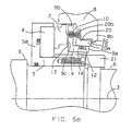
- Fig. 6 shows another embodiment of the invention.
- no tertiary seal 16 such as shown in Fig. 3a is provided by a separate sealing member.
- the tertiary seal is provided by direct sealing contact between a front face of a lip 8c formed integrally with the seal housing 8 and protruding axially and forwardly from the radially inward flange 8b of the seal housing 8, and the rear face of the axially extending portion 20a of auxiliary sleeve 20.
- the lip can be formed integrally on and protrude rearwardly from the axially extending portion 20a of auxiliary sleeve 20, to seal against a transverse front face of the radially inward flange 8b.
- a secondary seal 13 in the form of a separate component as in the Figs. 3, 3a embodiment is avoided by providing a lip 9c, protruding forwardly from the front face of and formed integrally with the radial flange 9b of pusher sleeve 9 as shown in Fig. 6, the lip being in direct sealing contact with the rear face of sealing ring 2.
- the lip 9c can be formed integrally on the rear face of the sealing ring 2 and protrude rearwardly to seal against the front face of the radial flange 9b of the pusher sleeve 9.
- Fig. 6a shows the shaft seal under working conditions.
- a fourth embodiment of the invention shown in Fig. 7 is a modification to the pusher sleeve 9 of the third embodiment.
- the pusher sleeve which is a single-part component, is replaced with a two-part pusher sleeve, comprising an inner pusher sleeve element 23 with an axially extending portion 23a and a radial flange 23b at the front end of axially extending portion 23a, and an outer annular pusher disc 22, the pusher disc being coaxially disposed around the inner pusher sleeve 23.
- a front face 22' of an inner radial portion of the pusher disc 22 is maintained sealingly in contact with the rear face 23' of the radial flange 23b.
- the pusher sleeve 23 seals against the sealing ring 2 through a lip 23c protruding forwardly from the front face of radial flange 23b, the lip being formed integrally with the radial flange 23b and in direct contact with the rear face of sealing ring 2.
- the lip can be formed integrally on the rear face of the sealing ring 2 and protrude rearwardly to seal against a front face of radial flange 23b.
- One advantage of a two-part pusher sleeve is that torsional forces, as encountered in the region of the junction between the radial portion 9b and the axially extending portion 9a of the single-component pusher sleeve 9, when the shaft seal is in operation, are largely eliminated.
- a fifth embodiment of the invention shown in Fig. 8 is a modification to the fourth embodiment.
- the auxiliary sleeve 20, which is a single-part component is replaced by a two-part auxiliary sleeve comprising an inner auxiliary sleeve element 24 and an outer annular auxiliary disc 25.
- the outer annular auxiliary disc is coaxially disposed around the inner auxiliary sleeve element 24 at its forward end, and the inner auxiliary sleeve element and the outer annular auxiliary disc have respective front and rear radial surfaces 24' and 25' sealingly maintained in contact with one another.
- the pusher sleeve is of one-part construction (such as described with reference to Figures 6, 6a) and the auxiliary sleeve is of two-part construction (such as described with reference to Figure 8).
- an advantage of replacing the single-component auxiliary sleeve with a two-part auxiliary sleeve is that torsional forces, as encountered.in the region of the junction between the radial flange 20b and the axially extending portion 20a of the single-component auxiliary sleeve 20 when the shaft seal is in operation, are largely eliminated. Also, when in operation, the two-part auxiliary sleeve deforms in a compliant manner with the deformation of the pusher sleeve.
- the lip seal arrangements used in the embodiments shown in Figs. 6, 6a, 7 and 8 avoid the use of separate sealing members serving as the secondary seal 13 and the tertiary seal 16 according to the embodiment shown in Figs. 3, 3a. This results in a constructional simplification and hence lower cost.
- a wave spring for example in the form of a single annulus of suitable sheet material, e.g. metal, (or several stacked together) may be deformed so as to form successive undulations at different angular positions about the axis of the annulus.
- the deformed annulus is compressed between the primary sealing ring 2 and the auxiliary sleeve 20 or radially inward flange 8b (as the case may be), thereby providing the required biasing action in the manner of a leaf spring.
- the source of the high-pressure fluid is the working fluid of the compressor, whose pressure accordingly increases with increasing compressor operating speed.
- a separate source of high-pressure fluid from the working fluid is used, its pressure will normally be held at a given delivery pressure.
- the net force acting on the primary seal is preferably a closing force, maintaining the sealing ring 2 against the sealing ring 4.
- the separating force generated by the tapered grooves or recesses in the one sealing ring or the other of the primary seal is sufficient to separate the two rings. Therefore, the operation is essentially the same as in the case where the working fluid of the compressor is the source of the high-pressure fluid.
- the sealing ring 2 is held against the sealing ring 4 when the compressor is at rest, it is possible for the shaft seal to be slightly open under rest conditions, since the essential requirement is merely that the shaft seal provides contactless operation when the compressor is operating at normal operational speed.
Landscapes
- Engineering & Computer Science (AREA)
- General Engineering & Computer Science (AREA)
- Mechanical Engineering (AREA)
- Mechanical Sealing (AREA)
Abstract
Claims (18)
- Dispositif d'étanchéité d'arbre comprenant une pièce d'étanchéité (2), un dispositif d'étanchéité rotatif (4) monté de manière coaxiale avec la pièce d'étanchéité et formant avec celle-ci un joint primaire sans contact entre les surfaces opposées de la pièce d'étanchéité (2) et du dispositif d'étanchéité rotatif (4) pour empêcher considérablement l'écoulement de fluide à travers le joint primaire depuis un côté radial haute pression vers un côté radial basse pression, un logement d'étanchéité (8), un manchon poussoir (9) disposé, entre le logement d'étanchéité et la pièce d'étanchéité, monté de manière coaxiale et en contact avec la pièce d'étanchéité (2), un moyen de sollicitation (10) éloignant le manchon poussoir (9) du logement d'étanchéité (8) et le poussant contre la pièce d'étanchéité (2) pour presser de manière axiale la pièce d'étanchéité vers le dispositif d'étanchéité rotatif (4), et un premier élément d'étanchéité (12) disposé sur le manchon poussoir (9) et situé, dans un canal (14), en communication avec le côté radial haute pression afin d'offrir un joint secondaire pour le manchon poussoir (9) entre les côtés radiaux haute et basse pression, caractérisés par un manchon auxiliaire (20) disposé autour du manchon poussoir (9) de manière coaxiale avec celui-ci et maintenu en contact étanche avec le manchon poussoir (9) grâce au premier élément d'étanchéité (12), le manchon auxiliaire étant agencé de manière à être poussé dans une direction axiale par la pression du fluide agissant du côté radial haute pression pour former un joint tertiaire (16) entre le manchon auxiliaire (20) et le logement d'étanchéité (8).
- Dispositif d'étanchéité d'arbre selon la revendication 1, dans lequel ledit canal (14) dans lequel ledit premier élément d'étanchéité (12) est situé, est formé dans le manchon poussoir (9).
- Dispositif d'étanchéité d'arbre selon la revendication 1, dans lequel ledit canal (14) dans lequel ledit premier élément d'étanchéité (12) est situé, est formé dans le manchon auxiliaire (20).
- Dispositif d'étanchéité d'arbre selon l'une des revendications précédentes, dans lequel le moyen de sollicitation (10) agit entre le manchon poussoir (9) et le manchon auxiliaire (20).
- Dispositif d'étanchéité d'arbre selon l'une quelconque des revendications 1 à 3, dans lequel le moyen de sollicitation (10) agit entre le logement d'étanchéité (8) et le manchon poussoir (9).
- Dispositif d'étanchéité d'arbre selon l'une des revendications précédentes, dans lequel le joint tertiaire (16) est doté d'un contact face à face entre les faces transversales du manchon auxiliaire et le logement d'étanchéité, lorsque le dispositif d'étanchéité d'arbre est utilisé.
- Dispositif d'étanchéité d'arbre selon l'une quelconque des revendications 1 à 5, dans lequel le joint tertiaire (16) comprend un joint torique (17) situé dans un canal (18) formé dans la face d'extrémité transversale du manchon auxiliaire (9).
- Dispositif d'étanchéité d'arbre selon l'une quelconque des revendications 1 à 5, dans lequel le joint tertiaire (16) comprend un joint torique (17) situé dans un canal (18) formé dans la face d'extrémité transversale du logement d'étanchéité (8).
- Dispositif d'étanchéité d'arbre selon l'une quelconque des revendications 1 à 5, dans lequel le joint tertiaire (16) comprend un joint en U actionné par ressort.
- Dispositif d'étanchéité d'arbre selon l'une quelconque des revendications 1 à 5, dans lequel le joint tertiaire (16) est un joint en Y actionné par ressort.
- Dispositif d'étanchéité d'arbre selon l'une des revendications précédentes, dans lequel le manchon poussoir (9) comprend une portion principale (9a) s'étendant axialement avec un rebord radial (9b) à l'une des extrémités en contact face à face avec la pièce d'étanchéité (2) et le manchon auxiliaire (20) comprend également une portion principale s'étendant axialement avec un rebord radial (20b) à l'une des extrémités orientée vers la bride (9a) du manchon poussoir (9).
- Dispositif d'étanchéité d'arbre selon l'une quelconque des revendications 1 à 10, dans lequel le manchon poussoir (9) comprend une portion principale (9a) s'étendant axialement avec un rebord radial (9b) à l'une des extrémités en contact face à face avec la pièce d'étanchéité (2) et le manchon auxiliaire (20) se présente sous la forme d'un manchon sur la totalité de sa longueur.
- Dispositif d'étanchéité d'arbre selon l'une des revendications précédentes, comprenant en plus un autre joint secondaire (13) entre les surfaces radiales adjacentes de ladite pièce d'étanchéité (2) et dudit manchon poussoir (9).
- Dispositif d'étanchéité d'arbre selon l'une quelconque des revendications 1 à 4, dans lequel ledit joint tertiaire (16) est équipé d'une lèvre (8c) formée intégralement sur, et faisant saillie depuis, l'un desdits logement d'étanchéité (8) et manchon auxiliaire (20) et dépassant de ce dernier, ladite lèvre formant un contact étanche avec l'autre partie dudit logement d'étanchéité et ledit manchon auxiliaire.
- Dispositif d'étanchéité d'arbre selon la revendication 13 telle qu'elle est jointe à l'une quelconque des revendications 1 à 11, ou selon la revendication 14, dans lequel ledit joint secondaire (13) entre ladite pièce d'étanchéité (2) et ledit manchon poussoir (9) est équipé d'une lèvre (8c) formée intégralement sur l'un desdits manchon poussoir (9) et pièce d'étanchéité (2) et dépassant de ce dernier, ladite lèvre formant un contact étanche avec l'autre partie dudit élément poussoir et de ladite pièce d'étanchéité.
- Dispositif d'étanchéité d'arbre selon la revendication 14 ou 15, dans lequel ledit manchon poussoir (9) comprend un élément manchon poussoir interne (23) et un disque poussoir annulaire externe (22), ledit élément manchon poussoir interne et ledit disque poussoir annulaire externe possédant respectivement des surfaces radiales (23', 22') maintenues en contact entre elles.
- Dispositif d'étanchéité d'arbre selon la revendication 14, 15 ou 16, dans lequel ledit manchon auxiliaire (20) comprend un élément manchon auxiliaire interne (24) et un disque auxiliaire annulaire externe (25), ledit élément manchon auxiliaire interne et ledit disque auxiliaire annulaire externe possédant respectivement des surfaces radiales (24', 25') maintenues en contact entre elles.
- Turbomachine ou une autre machine sous pression comprenant un dispositif d'étanchéité d'arbre selon l'une quelconque des revendications précédentes.
Priority Applications (1)
| Application Number | Priority Date | Filing Date | Title |
|---|---|---|---|
| EP00914089A EP1153233B1 (fr) | 1999-02-25 | 2000-02-25 | Dispositif d'etancheite d'arbre |
Applications Claiming Priority (4)
| Application Number | Priority Date | Filing Date | Title |
|---|---|---|---|
| EP99400460 | 1999-02-25 | ||
| EP99400460A EP1031775A1 (fr) | 1999-02-25 | 1999-02-25 | Joint d'étanchéité d'arbre |
| PCT/EP2000/001579 WO2000050789A1 (fr) | 1999-02-25 | 2000-02-25 | Dispositif d'etancheite d'arbre |
| EP00914089A EP1153233B1 (fr) | 1999-02-25 | 2000-02-25 | Dispositif d'etancheite d'arbre |
Publications (2)
| Publication Number | Publication Date |
|---|---|
| EP1153233A1 EP1153233A1 (fr) | 2001-11-14 |
| EP1153233B1 true EP1153233B1 (fr) | 2004-01-02 |
Family
ID=8241890
Family Applications (2)
| Application Number | Title | Priority Date | Filing Date |
|---|---|---|---|
| EP99400460A Withdrawn EP1031775A1 (fr) | 1999-02-25 | 1999-02-25 | Joint d'étanchéité d'arbre |
| EP00914089A Expired - Lifetime EP1153233B1 (fr) | 1999-02-25 | 2000-02-25 | Dispositif d'etancheite d'arbre |
Family Applications Before (1)
| Application Number | Title | Priority Date | Filing Date |
|---|---|---|---|
| EP99400460A Withdrawn EP1031775A1 (fr) | 1999-02-25 | 1999-02-25 | Joint d'étanchéité d'arbre |
Country Status (7)
| Country | Link |
|---|---|
| US (2) | US6601854B2 (fr) |
| EP (2) | EP1031775A1 (fr) |
| JP (1) | JP4684420B2 (fr) |
| AU (1) | AU3553000A (fr) |
| CA (1) | CA2362182A1 (fr) |
| DE (1) | DE60007513T2 (fr) |
| WO (1) | WO2000050789A1 (fr) |
Families Citing this family (26)
| Publication number | Priority date | Publication date | Assignee | Title |
|---|---|---|---|---|
| JP3933469B2 (ja) * | 2001-12-28 | 2007-06-20 | イーグル工業株式会社 | メカニカルシール装置 |
| GB0317055D0 (en) * | 2003-07-22 | 2003-08-27 | Cross Mfg Co 1938 Ltd | Improvements relating to aspirating face seals and thrust bearings |
| US20050242515A1 (en) * | 2004-04-28 | 2005-11-03 | Brooks Melvin D | Dry gas seal and method for making the same |
| ZA200507096B (en) * | 2004-09-07 | 2006-06-28 | Crane John Inc | Sealing system for slurry pump |
| US20060188381A1 (en) * | 2005-02-24 | 2006-08-24 | Honeywell International, Inc. | Seal assembly for hydraulic pump output shaft |
| DE202005011137U1 (de) * | 2005-07-14 | 2005-09-29 | Burgmann Industries Gmbh & Co. Kg | Gleitringdichtungsanordnung |
| GB0605510D0 (en) * | 2006-03-18 | 2006-04-26 | Crane John Uk Ltd | High pressure gas seals |
| GB0806253D0 (en) * | 2008-04-07 | 2008-05-14 | Cross Mfg 1938 Company Ltd | Non-contacting face seals and thrust bearings |
| US20090252595A1 (en) * | 2008-04-07 | 2009-10-08 | Cross Manufacturing Co. )1983) Ltd. | Non-contacting face seals and thrust bearings |
| CA2755496C (fr) * | 2009-03-16 | 2017-10-31 | Vulco S.A. | Joint mecanique ajustable |
| AU2013204370B2 (en) * | 2009-03-16 | 2016-11-17 | Vulco S.A. | Mechanical seal |
| US20100253005A1 (en) * | 2009-04-03 | 2010-10-07 | Liarakos Nicholas P | Seal for oil-free rotary displacement compressor |
| DE102010024291B4 (de) * | 2010-04-23 | 2013-04-18 | Carl Freudenberg Kg | Gleitringdichtung mit rotierendem Gegenring mit exakt definierter Einspannung |
| GB201013844D0 (en) * | 2010-08-19 | 2010-09-29 | Rolls Royce Plc | Intershaft seal |
| US8814547B2 (en) * | 2011-02-25 | 2014-08-26 | Hamilton Sundstrand Corporation | Seal retaining sleeve for gear pump |
| JP5712067B2 (ja) * | 2011-06-27 | 2015-05-07 | 株式会社日立製作所 | 高温流体用軸封装置 |
| US9190312B2 (en) | 2011-07-27 | 2015-11-17 | Advanced Ion Beam Technology, Inc. | Extremely low temperature rotary union |
| KR102002562B1 (ko) * | 2012-11-28 | 2019-07-22 | 한화파워시스템 주식회사 | 가스 실 어셈블리 |
| JP6509896B2 (ja) | 2014-11-04 | 2019-05-08 | イーグル工業株式会社 | メカニカルシール装置 |
| EP3217048B1 (fr) * | 2014-11-04 | 2020-09-16 | Eagle Industry Co., Ltd. | Dispositif de garniture mécanique |
| US10234036B2 (en) | 2015-01-12 | 2019-03-19 | Rolls-Royce Corporation | Wide differential pressure range air riding carbon seal |
| WO2017123502A1 (fr) * | 2016-01-13 | 2017-07-20 | Ball Corporation | Système et procédé d'orientation de la direction de laminage d'une ébauche d'extrémité dans un processus de fabrication de récipients métalliques |
| KR101695255B1 (ko) * | 2016-03-07 | 2017-01-12 | 한화테크윈 주식회사 | 가스 실 어셈블리 |
| US10697548B2 (en) | 2016-04-27 | 2020-06-30 | Eagle Industry Co., Ltd. | Mechanical seal |
| US12110967B2 (en) * | 2022-12-30 | 2024-10-08 | Onesubsea Ip Uk Limited | Dynamic axial seal systems and methods |
| CN119177884A (zh) * | 2023-06-23 | 2024-12-24 | 通用电气公司 | 对壳体振动具有鲁棒性的面密封件 |
Family Cites Families (29)
| Publication number | Priority date | Publication date | Assignee | Title |
|---|---|---|---|---|
| US3515394A (en) * | 1964-06-05 | 1970-06-02 | Sealol | Vibration damping means for resilient convoluted members |
| US3580587A (en) * | 1967-07-22 | 1971-05-25 | Klein Schanzlin & Becker Ag | Contact-free hydrostatic seal |
| US3475033A (en) * | 1967-12-01 | 1969-10-28 | Continental Illinois National | Liquid sensing seal for rotating shaft |
| JPS5712305Y2 (fr) * | 1976-07-23 | 1982-03-11 | ||
| US4095806A (en) * | 1977-07-05 | 1978-06-20 | The Babcock & Wilcox Company | Seal arrangement |
| US4212475A (en) * | 1979-01-15 | 1980-07-15 | Crane Packing Co. | Self aligning spiral groove face seal |
| US4191386A (en) * | 1978-01-16 | 1980-03-04 | Durametallic Corporation | Self-cooled mechanical seal |
| JPS6051360A (ja) * | 1983-08-31 | 1985-03-22 | Canon Inc | 画像形成装置 |
| US5244215A (en) * | 1985-05-10 | 1993-09-14 | Chicago Rawhide Manufacturing Company | Rotary shaft seal with retractable excluder lip |
| US4872517A (en) * | 1988-02-08 | 1989-10-10 | Shaw Daniel G | Rotatable fluid conductor for well apparatus |
| JP2648816B2 (ja) * | 1988-05-10 | 1997-09-03 | イーグル工業株式会社 | 円筒面シール |
| CH680526A5 (fr) * | 1989-11-06 | 1992-09-15 | Escher Wyss Ag | |
| US5224714A (en) * | 1990-07-18 | 1993-07-06 | Ebara Corporation | Noncontacting face seal |
| JPH083763Y2 (ja) | 1992-09-03 | 1996-01-31 | 日本ピラー工業株式会社 | 非接触型メカニカルシール |
| US5421593A (en) | 1993-08-05 | 1995-06-06 | Nippon Pillar Packing Co., Ltd. | Shaft seal device |
| US5503407A (en) * | 1994-04-18 | 1996-04-02 | Stein Seal Company | Windbacks for rotating shafts |
| US5558342A (en) * | 1994-08-05 | 1996-09-24 | Durametallic Corporation | Mechanical seal with spring drive |
| US6213472B1 (en) | 1994-11-16 | 2001-04-10 | Dresser-Rand Company | Shaft seal |
| JP2790063B2 (ja) * | 1994-11-29 | 1998-08-27 | 日本ジョン・クレーン株式会社 | メカニカルシール |
| GB9508034D0 (en) | 1995-04-20 | 1995-06-07 | Dresser Rand Co | A shaft seal |
| GB2300028B (en) | 1995-04-20 | 1999-02-10 | Dresser Rand Co | A shaft seal |
| US5954341A (en) * | 1996-07-30 | 1999-09-21 | John Crane Sealol Inc. | Bellows seal with drive collar for reverse pressure capability |
| US5681047A (en) * | 1996-11-01 | 1997-10-28 | John Crane Inc. | Pressure responsive primary ring geometry for a non-contacting mechanical end face seal |
| US5938206A (en) * | 1996-11-01 | 1999-08-17 | John Crane Inc. | Pressure responsive primary ring for a non-contacting mechanical end face seal |
| US5924697A (en) * | 1997-03-03 | 1999-07-20 | Durametallic Corporation | Double gas seal with bellows supported by backing and support rings |
| US6267382B1 (en) * | 1998-02-23 | 2001-07-31 | Dresser-Rand Company | Fail safe L-shaped spring carrier for gas seals |
| JP3650954B2 (ja) * | 1998-09-18 | 2005-05-25 | イーグル工業株式会社 | 高速用非接触型メカニカルシール |
| US6182971B1 (en) * | 1998-12-09 | 2001-02-06 | Flowserve Management Company | Gas seal for pumps |
| US6293555B1 (en) * | 2000-02-01 | 2001-09-25 | Josef Sedy | Secondary seal for non-contacting face seals |
-
1999
- 1999-02-25 EP EP99400460A patent/EP1031775A1/fr not_active Withdrawn
-
2000
- 2000-02-25 JP JP2000601348A patent/JP4684420B2/ja not_active Expired - Lifetime
- 2000-02-25 CA CA002362182A patent/CA2362182A1/fr not_active Abandoned
- 2000-02-25 AU AU35530/00A patent/AU3553000A/en not_active Abandoned
- 2000-02-25 DE DE60007513T patent/DE60007513T2/de not_active Expired - Lifetime
- 2000-02-25 EP EP00914089A patent/EP1153233B1/fr not_active Expired - Lifetime
- 2000-02-25 WO PCT/EP2000/001579 patent/WO2000050789A1/fr not_active Ceased
-
2001
- 2001-08-23 US US09/938,175 patent/US6601854B2/en not_active Expired - Lifetime
-
2003
- 2003-01-16 US US10/345,569 patent/US6916022B2/en not_active Expired - Lifetime
Also Published As
| Publication number | Publication date |
|---|---|
| EP1153233A1 (fr) | 2001-11-14 |
| US20030107179A1 (en) | 2003-06-12 |
| CA2362182A1 (fr) | 2000-08-31 |
| JP2002538384A (ja) | 2002-11-12 |
| EP1031775A1 (fr) | 2000-08-30 |
| WO2000050789A1 (fr) | 2000-08-31 |
| DE60007513D1 (de) | 2004-02-05 |
| US6601854B2 (en) | 2003-08-05 |
| US20020047239A1 (en) | 2002-04-25 |
| AU3553000A (en) | 2000-09-14 |
| US6916022B2 (en) | 2005-07-12 |
| DE60007513T2 (de) | 2004-11-11 |
| JP4684420B2 (ja) | 2011-05-18 |
Similar Documents
| Publication | Publication Date | Title |
|---|---|---|
| EP1153233B1 (fr) | Dispositif d'etancheite d'arbre | |
| EP1163463B1 (fr) | Joint pour arbre tournant | |
| EP0578377B1 (fr) | Joint d'étanchéité | |
| US6347800B1 (en) | Fail safe L-shaped spring carrier for gas seals | |
| US4659092A (en) | Mechanical seals | |
| US5224714A (en) | Noncontacting face seal | |
| US5938206A (en) | Pressure responsive primary ring for a non-contacting mechanical end face seal | |
| CA2279558C (fr) | Dispositif etanche ayant un systeme de reglage d'ecartement automatique | |
| JPH10281299A (ja) | メカニカルシール装置 | |
| US5681047A (en) | Pressure responsive primary ring geometry for a non-contacting mechanical end face seal | |
| US6267382B1 (en) | Fail safe L-shaped spring carrier for gas seals | |
| US11287043B2 (en) | High clearance seal assembly | |
| US6131913A (en) | Anti-rotation and axial locking arrangement of a gas seal on its sleeve | |
| US5192083A (en) | Single ring sector seal | |
| US5026076A (en) | Mechanical face seals | |
| US5487550A (en) | Secondary gas/liquid mechanical seal assembly |
Legal Events
| Date | Code | Title | Description |
|---|---|---|---|
| PUAI | Public reference made under article 153(3) epc to a published international application that has entered the european phase |
Free format text: ORIGINAL CODE: 0009012 |
|
| 17P | Request for examination filed |
Effective date: 20010829 |
|
| AK | Designated contracting states |
Kind code of ref document: A1 Designated state(s): AT BE CH CY DE DK ES FI FR GB GR IE IT LI LU MC NL PT SE |
|
| AX | Request for extension of the european patent |
Free format text: AL;LT;LV;MK;RO;SI |
|
| GRAP | Despatch of communication of intention to grant a patent |
Free format text: ORIGINAL CODE: EPIDOSNIGR1 |
|
| GRAS | Grant fee paid |
Free format text: ORIGINAL CODE: EPIDOSNIGR3 |
|
| GRAA | (expected) grant |
Free format text: ORIGINAL CODE: 0009210 |
|
| AK | Designated contracting states |
Kind code of ref document: B1 Designated state(s): CH DE FR GB IT LI |
|
| REG | Reference to a national code |
Ref country code: GB Ref legal event code: FG4D |
|
| REG | Reference to a national code |
Ref country code: CH Ref legal event code: EP |
|
| REG | Reference to a national code |
Ref country code: IE Ref legal event code: FG4D |
|
| REF | Corresponds to: |
Ref document number: 60007513 Country of ref document: DE Date of ref document: 20040205 Kind code of ref document: P |
|
| REG | Reference to a national code |
Ref country code: CH Ref legal event code: NV Representative=s name: BOVARD AG PATENTANWAELTE |
|
| LTIE | Lt: invalidation of european patent or patent extension |
Effective date: 20040102 |
|
| ET | Fr: translation filed | ||
| PLBE | No opposition filed within time limit |
Free format text: ORIGINAL CODE: 0009261 |
|
| STAA | Information on the status of an ep patent application or granted ep patent |
Free format text: STATUS: NO OPPOSITION FILED WITHIN TIME LIMIT |
|
| REG | Reference to a national code |
Ref country code: IE Ref legal event code: MM4A |
|
| 26N | No opposition filed |
Effective date: 20041005 |
|
| REG | Reference to a national code |
Ref country code: CH Ref legal event code: PFA Owner name: DRESSER RAND S.A Free format text: DRESSER RAND S.A#74, RUE D'ARCUEIL, SILIC 265#94578 RUNGIS CEDEX (FR) -TRANSFER TO- DRESSER RAND S.A#74, RUE D'ARCUEIL, SILIC 265#94578 RUNGIS CEDEX (FR) |
|
| REG | Reference to a national code |
Ref country code: FR Ref legal event code: PLFP Year of fee payment: 16 |
|
| REG | Reference to a national code |
Ref country code: FR Ref legal event code: PLFP Year of fee payment: 17 |
|
| REG | Reference to a national code |
Ref country code: DE Ref legal event code: R082 Ref document number: 60007513 Country of ref document: DE Representative=s name: MAIER, DANIEL OLIVER, DIPL.-ING. UNIV., DE |
|
| REG | Reference to a national code |
Ref country code: FR Ref legal event code: PLFP Year of fee payment: 18 |
|
| REG | Reference to a national code |
Ref country code: FR Ref legal event code: PLFP Year of fee payment: 19 |
|
| PGFP | Annual fee paid to national office [announced via postgrant information from national office to epo] |
Ref country code: GB Payment date: 20190213 Year of fee payment: 20 Ref country code: IT Payment date: 20190226 Year of fee payment: 20 |
|
| PGFP | Annual fee paid to national office [announced via postgrant information from national office to epo] |
Ref country code: FR Payment date: 20190208 Year of fee payment: 20 |
|
| PGFP | Annual fee paid to national office [announced via postgrant information from national office to epo] |
Ref country code: DE Payment date: 20190416 Year of fee payment: 20 |
|
| PGFP | Annual fee paid to national office [announced via postgrant information from national office to epo] |
Ref country code: CH Payment date: 20190509 Year of fee payment: 20 |
|
| REG | Reference to a national code |
Ref country code: DE Ref legal event code: R071 Ref document number: 60007513 Country of ref document: DE |
|
| REG | Reference to a national code |
Ref country code: CH Ref legal event code: PL |
|
| REG | Reference to a national code |
Ref country code: GB Ref legal event code: PE20 Expiry date: 20200224 |
|
| PG25 | Lapsed in a contracting state [announced via postgrant information from national office to epo] |
Ref country code: GB Free format text: LAPSE BECAUSE OF EXPIRATION OF PROTECTION Effective date: 20200224 |