EP1153631A2 - Saitenklemmmechanismus in einem Bespannungsapparat für Tennisschläger - Google Patents
Saitenklemmmechanismus in einem Bespannungsapparat für Tennisschläger Download PDFInfo
- Publication number
- EP1153631A2 EP1153631A2 EP00204779A EP00204779A EP1153631A2 EP 1153631 A2 EP1153631 A2 EP 1153631A2 EP 00204779 A EP00204779 A EP 00204779A EP 00204779 A EP00204779 A EP 00204779A EP 1153631 A2 EP1153631 A2 EP 1153631A2
- Authority
- EP
- European Patent Office
- Prior art keywords
- gut
- holder
- holders
- clamping mechanism
- support post
- Prior art date
- Legal status (The legal status is an assumption and is not a legal conclusion. Google has not performed a legal analysis and makes no representation as to the accuracy of the status listed.)
- Granted
Links
- 238000010586 diagram Methods 0.000 description 8
- 239000000463 material Substances 0.000 description 5
- 229910001234 light alloy Inorganic materials 0.000 description 2
- 229920003023 plastic Polymers 0.000 description 2
- 239000004033 plastic Substances 0.000 description 2
- 230000003014 reinforcing effect Effects 0.000 description 2
- 229910001369 Brass Inorganic materials 0.000 description 1
- RYGMFSIKBFXOCR-UHFFFAOYSA-N Copper Chemical compound [Cu] RYGMFSIKBFXOCR-UHFFFAOYSA-N 0.000 description 1
- 229910000831 Steel Inorganic materials 0.000 description 1
- 239000010951 brass Substances 0.000 description 1
- 238000010276 construction Methods 0.000 description 1
- 229910052802 copper Inorganic materials 0.000 description 1
- 239000010949 copper Substances 0.000 description 1
- 238000003780 insertion Methods 0.000 description 1
- 230000037431 insertion Effects 0.000 description 1
- 238000005461 lubrication Methods 0.000 description 1
- 238000012423 maintenance Methods 0.000 description 1
- 239000002184 metal Substances 0.000 description 1
- 229910052751 metal Inorganic materials 0.000 description 1
- 239000010959 steel Substances 0.000 description 1
- 239000013585 weight reducing agent Substances 0.000 description 1
Images




Classifications
-
- A—HUMAN NECESSITIES
- A63—SPORTS; GAMES; AMUSEMENTS
- A63B—APPARATUS FOR PHYSICAL TRAINING, GYMNASTICS, SWIMMING, CLIMBING, OR FENCING; BALL GAMES; TRAINING EQUIPMENT
- A63B51/00—Stringing tennis, badminton or like rackets; Strings therefor; Maintenance of racket strings
- A63B51/14—Arrangements for stringing, e.g. for controlling the tension of the strings during stringing
-
- A—HUMAN NECESSITIES
- A63—SPORTS; GAMES; AMUSEMENTS
- A63B—APPARATUS FOR PHYSICAL TRAINING, GYMNASTICS, SWIMMING, CLIMBING, OR FENCING; BALL GAMES; TRAINING EQUIPMENT
- A63B51/00—Stringing tennis, badminton or like rackets; Strings therefor; Maintenance of racket strings
- A63B51/14—Arrangements for stringing, e.g. for controlling the tension of the strings during stringing
- A63B51/16—Apparatus for stringing while manufacturing
-
- Y—GENERAL TAGGING OF NEW TECHNOLOGICAL DEVELOPMENTS; GENERAL TAGGING OF CROSS-SECTIONAL TECHNOLOGIES SPANNING OVER SEVERAL SECTIONS OF THE IPC; TECHNICAL SUBJECTS COVERED BY FORMER USPC CROSS-REFERENCE ART COLLECTIONS [XRACs] AND DIGESTS
- Y10—TECHNICAL SUBJECTS COVERED BY FORMER USPC
- Y10T—TECHNICAL SUBJECTS COVERED BY FORMER US CLASSIFICATION
- Y10T29/00—Metal working
- Y10T29/53—Means to assemble or disassemble
- Y10T29/53696—Means to string
Definitions
- This invention relates to a gut-clamping mechanism in gut-stretching equipment for tennis rackets.
- gut-stretching equipment for tennis and badminton rackets consists of a racket anchor block 100, 100; a gut-clamping mechanism 101,1001; and a tension unit 102 that stretches catguts with a prescribed pressure.
- the gut-clamping mechanism 101 consists of the following components: a clamp block 101A that can freely move right and left along a guide rail (not shown in the figure); a support post 101B that is erected on the clamp block 101A; a pair of holders 101C wherein one holder, 101C', is fixed onto the top edge of said support post and the other holder, 101C", is provided in a detachable manner with respect to the other holder, 101C', and wherein an expanding coil spring (not shown in the figure) is inserted between them; a pressing plate 101G that has a shaft 101D that goes through said pair of holders 101C when they are joined together as well as a fastening, adjusting nut 101F at a screw unit 101E that is etched and provided at the tip of said shaft 101D; and a clamp handle 101H that is axially installed on one edge of said pressing plate 101G.
- reference number 101I denotes a pressure-adjusting screw for the clamp block 101A and the rail; and 101J
- a gut is clamped by pressing the clamp handle 101H down. This causes the lower edge of the pressing plate 101G to tilt outward and the upper edge to tilt inward, thus pressing one of the holders 101" so that the gut can be clamped between the pair of holders 101C.
- clamp handles are designed to open and close the pawl by employing a sliding action.
- these clamp handles employ the principles of metal bearings, wherein expensive materials, such as copper and brass, are used in the clamp handle 101H.
- the part A that serves as the receptacle for the other holder quenched steel is mirror-surface polished and fitted in for maximum sliding efficiency, such that the wear occurs mostly on the handle, so as to protect the main unit.
- the other holder 101C' that receives the clamp handle requires a fortifying material and labor, which adds to the high cost.
- the present invention was developed in view of the above situation, the purpose thereof being to provide an inexpensive and light-weight gut-clamping mechanism for tennis rackets that uses a roller to reduce the wear on the mutual contact point between the clamp handle and the holders so that inexpensive materials, such as light alloys and plastics, can be used for the construction of the clamp handle, so as to eliminate the need for a reinforcing means on the holder side that comes into contact with the clamp handle.
- the gist of the present invention is as follows: in a gut-clamping mechanism comprising a support post erected on a clamp block; a pair of holders wherein one holder is secured onto the top edge of said support post and the other holder is provided on the first holder on a detachable manner, such that an expanding coil spring is inserted between them; a pressing plate that has a shaft that goes through said pair of holders when the holders are joined together and with a fastening, adjustment nut hinged on the screw unit that is etched and provided at the tip of said shaft; and a clamp handle that is axially attached to an edge of said pressing plate; a gut-clamping mechanism in gut-stretching equipment for tennis rackets, wherein a freely rotating roller is axially attached to the contact part with the said of the holder that is secured onto the support post in the clamp handle.
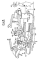
- Fig. 1 is a slanted-view diagram of an embodiment of the present invention.
- Fig. 2 is a slanted-view diagram of a pressing plate and a clamp handle.
- Fig. 3 is a slanted-view diagram of the clamp handle with the roller removed.
- Fig. 4 is a center cross-section lateral diagram of the clamp handle.
- Fig. 5 is a slanted-view diagram of the conventional gut-stretching equipment for tennis rackets.
- Fig. 6 is a slanted-view diagram of a disassembled conventional gut-clamping mechanism.
- Fig. 7 is a slanted-view diagram of an assembled conventional gut-clamping mechanism.
- Fig. 8 is a slanted- view diagram of a conventional pressing plate and clamp handle.
- reference number 1 denotes a gut-clamping mechanism; 2 a clamp block; and 3, a support post that is erected on the clamp block 2.
- reference number 4 denotes a pair of holders consisting of 4' and another holder 4".
- One of the holders 4' is secured onto the top edge of the aforementioned post 3 and the other holder 4", is provided in a detachable manner on the first holder 4' through a shaft (more on this later).
- An expanding coil spring (not shown in the figure) is inserted between these holders 4' and 4", and the spring is always energized in an opening direction.
- the holders 4' and 4" are provided with through-holes (not shown in the figure) for the shaft (more on this later).
- Reference number 5 denotes a pressing plate; it has a shaft 6 that goes through the pair of holders 4 when they are joined together. Hinged on a screw 7 that is etched and provided at the tip of the shaft 6 is a fastening adjusting nut 8.
- Reference number 9 denotes a clamp handle that is axially attached to one end of the pressing plate 5 by means of an axis 10.
- a feature of the present invention lies in the provision of a freely rotating roller 11 in the section (part A in Fig. 8 illustrating the aforementioned conventional mechanism) that comes into contact with the holder 4' that is fixed onto the aforementioned support post 3 in the aforementioned clamp handle 9.
- reference number 12 denotes a rotary axis for the roller and 13 denotes a rotary axis insertion hole that is provided on the sidewall of the roller receptacle recess 9a on the clamp handle 9.
- the present invention consists of the above-described constitution and action. As such, by axially attaching a freely rotating roller to the clamp handle, the friction between the contacting faces on the clamp handle and one of the holders can be minimized. This permits the use of inexpensive materials, such as light alloys and plastics, for the clamp handle, and eliminates the need for a reinforcing means on the side of the holder that comes into contact with the roller, thereby substantially reducing costs and as well as the weight. This also eliminates the need for maintenance, such as the applicaiton of lubrication oil. Most significantly, the weight reduction substantially improves the performance of the entire clamping mechanism, which is used extremely frequently (stretching a racktet involves dozens of tightening and releasing operations).
Landscapes
- Health & Medical Sciences (AREA)
- General Health & Medical Sciences (AREA)
- Physical Education & Sports Medicine (AREA)
- Clamps And Clips (AREA)
- Load-Engaging Elements For Cranes (AREA)
- Tyre Moulding (AREA)
Applications Claiming Priority (2)
| Application Number | Priority Date | Filing Date | Title |
|---|---|---|---|
| JP2000133242A JP2001314532A (ja) | 2000-05-02 | 2000-05-02 | テニスラケット等のガット張り装置におけるガットクランプ機構 |
| JP2000133242 | 2000-05-02 |
Publications (3)
| Publication Number | Publication Date |
|---|---|
| EP1153631A2 true EP1153631A2 (de) | 2001-11-14 |
| EP1153631A3 EP1153631A3 (de) | 2003-12-17 |
| EP1153631B1 EP1153631B1 (de) | 2006-02-22 |
Family
ID=18641774
Family Applications (1)
| Application Number | Title | Priority Date | Filing Date |
|---|---|---|---|
| EP00204779A Expired - Lifetime EP1153631B1 (de) | 2000-05-02 | 2000-12-28 | Saitenklemmmechanismus in einem Bespannungsapparat für Tennisschläger |
Country Status (5)
| Country | Link |
|---|---|
| US (1) | US6398674B2 (de) |
| EP (1) | EP1153631B1 (de) |
| JP (1) | JP2001314532A (de) |
| AT (1) | ATE318170T1 (de) |
| DE (1) | DE60026111T2 (de) |
Cited By (1)
| Publication number | Priority date | Publication date | Assignee | Title |
|---|---|---|---|---|
| CN102188802A (zh) * | 2008-03-14 | 2011-09-21 | 威尔逊运动货品公司 | 球拍穿线机 |
Families Citing this family (12)
| Publication number | Priority date | Publication date | Assignee | Title |
|---|---|---|---|---|
| US6533687B1 (en) * | 2002-03-18 | 2003-03-18 | Min-Wei Lee | String clip positioning device of a racket string stretcher |
| CN100336571C (zh) * | 2002-12-24 | 2007-09-12 | 黄淑娥 | 改进的球拍穿线机 |
| US7252606B1 (en) * | 2006-06-23 | 2007-08-07 | Min-Wei Lee | Clamping device for clamping strings of stringing machine for sport rackets |
| US7686713B2 (en) * | 2007-04-11 | 2010-03-30 | Wilson Sporting Goods Co. | Racquet stringing machine |
| US7833118B2 (en) * | 2007-04-11 | 2010-11-16 | Wilson Sporting Goods Co. | Racquet stringing machine |
| US8066593B2 (en) * | 2007-04-11 | 2011-11-29 | Wilson Sporting Goods Co. | Customized racquet stringing system and method |
| US7695383B2 (en) * | 2007-04-11 | 2010-04-13 | Wilson Sporting Goods Co. | Racquet stringing machine |
| US8075429B2 (en) | 2007-04-11 | 2011-12-13 | Wilson Sporting Goods Co. | Racquet stringing machine |
| US8196913B2 (en) * | 2009-06-08 | 2012-06-12 | Min-Wei Lee | Clamping assembly for clamping strings of stringing machine for sport rackets |
| US9908009B1 (en) * | 2017-01-25 | 2018-03-06 | Min Wei Lee | String clamping device of threading machine for racket |
| TWI650161B (zh) * | 2018-05-29 | 2019-02-11 | 豐英有限公司 | 夾線器 |
| US11185960B2 (en) * | 2019-12-31 | 2021-11-30 | Min Wei Lee | Positioning structure of clamper of threading machine for racket |
Family Cites Families (10)
| Publication number | Priority date | Publication date | Assignee | Title |
|---|---|---|---|---|
| BE359094A (de) * | 1928-10-17 | 1900-01-01 | ||
| US2114216A (en) * | 1937-05-18 | 1938-04-12 | Doll Air Stringer Of America I | Racket stringing apparatus |
| US3441275A (en) * | 1967-03-03 | 1969-04-29 | Franklin W Held | Racket stringer |
| US3635080A (en) * | 1968-05-31 | 1972-01-18 | Court & Slope Inc | Racket-stringing machine with automatic locking |
| US4348024A (en) * | 1979-02-12 | 1982-09-07 | Balaban J A | Racket stringing apparatus and method |
| FR2475908A2 (fr) * | 1980-02-18 | 1981-08-21 | Montana Sport | Perfectionnements a la machine a corder les raquettes |
| FR2551351A1 (fr) * | 1983-09-02 | 1985-03-08 | Froger Pere Fils Gendre Sa | Dispositif de retenue de la tension d'une corde, notamment lors du cordage d'une raquette de tennis |
| JPS61154581A (ja) * | 1984-12-26 | 1986-07-14 | 榎 博久 | ガツト張り用補助具 |
| US5090697A (en) * | 1991-03-22 | 1992-02-25 | Poreex Industrial Co., Ltd. | Racket frame stringing machine |
| US6093121A (en) * | 1998-10-27 | 2000-07-25 | Bishop; Jonah C. | Swivel clamp for racket stringing |
-
2000
- 2000-05-02 JP JP2000133242A patent/JP2001314532A/ja active Pending
- 2000-12-28 DE DE60026111T patent/DE60026111T2/de not_active Expired - Fee Related
- 2000-12-28 EP EP00204779A patent/EP1153631B1/de not_active Expired - Lifetime
- 2000-12-28 AT AT00204779T patent/ATE318170T1/de not_active IP Right Cessation
-
2001
- 2001-04-16 US US09/836,063 patent/US6398674B2/en not_active Expired - Fee Related
Cited By (2)
| Publication number | Priority date | Publication date | Assignee | Title |
|---|---|---|---|---|
| CN102188802A (zh) * | 2008-03-14 | 2011-09-21 | 威尔逊运动货品公司 | 球拍穿线机 |
| CN102188802B (zh) * | 2008-03-14 | 2013-11-06 | 威尔逊运动货品公司 | 球拍穿线机 |
Also Published As
| Publication number | Publication date |
|---|---|
| DE60026111T2 (de) | 2006-10-26 |
| US6398674B2 (en) | 2002-06-04 |
| EP1153631A3 (de) | 2003-12-17 |
| US20010037546A1 (en) | 2001-11-08 |
| EP1153631B1 (de) | 2006-02-22 |
| DE60026111D1 (de) | 2006-04-27 |
| JP2001314532A (ja) | 2001-11-13 |
| ATE318170T1 (de) | 2006-03-15 |
Similar Documents
| Publication | Publication Date | Title |
|---|---|---|
| EP1153631B1 (de) | Saitenklemmmechanismus in einem Bespannungsapparat für Tennisschläger | |
| US8069848B1 (en) | Pillow block bearing assembly for compound bows | |
| US5267498A (en) | Fret-saw machine | |
| US6390954B1 (en) | Step exerciser | |
| US6984185B2 (en) | Device for gut stringing | |
| US10617902B2 (en) | Jump rope handles including systems and methods thereof | |
| US20080167147A1 (en) | Height Adjusting Device for Use in String Pulling Block of Stringing Machine | |
| US6449823B2 (en) | Golf club head removal tool | |
| JP2018034251A (ja) | バンドソー | |
| US9841660B1 (en) | Object guide having a variable motion path | |
| US7640855B2 (en) | Clamping device for a printing plate | |
| JP3271511B2 (ja) | 遮断器の投入ばね装置 | |
| US7252606B1 (en) | Clamping device for clamping strings of stringing machine for sport rackets | |
| PL1721379T3 (pl) | Maszyna jawnobiegunowa z co najmniej jedną cewką biegunową | |
| US8783147B2 (en) | Nibbling tool | |
| KR200478376Y1 (ko) | 볼헤드 패닝 잠금 장치 | |
| US6422353B1 (en) | Rotary coupling for brake assembly of cycles | |
| CN219262954U (zh) | 一种健身器材中的角度固定装置 | |
| KR200203936Y1 (ko) | 투포원 연사기의 크레들 | |
| JP2007021624A (ja) | 共まい防止用治具、フレーム固定用治具、アーム支持用治具、シャフト取外用治具、クランプ分解用治具セット、スプリング回転用治具、フレーム開幅用治具、スプリング圧縮用治具セット、クランプ組立用治具セット、クランプ分解方法、及び、クランプ組立方法 | |
| US20040134255A1 (en) | Magnetic dent removal device, method and kit | |
| CN222190349U (zh) | 一种自动调节治具 | |
| KR200240596Y1 (ko) | 롤러가 결합된 스프링 가공용 밴딩 바이스 | |
| US5846146A (en) | Device for repairing or replacing a broken string on a racket | |
| CN218506351U (zh) | 一种标签剥离导板结构 |
Legal Events
| Date | Code | Title | Description |
|---|---|---|---|
| PUAI | Public reference made under article 153(3) epc to a published international application that has entered the european phase |
Free format text: ORIGINAL CODE: 0009012 |
|
| AK | Designated contracting states |
Kind code of ref document: A2 Designated state(s): AT BE CH CY DE DK ES FI FR GB GR IE IT LI LU MC NL PT SE TR |
|
| AX | Request for extension of the european patent |
Free format text: AL;LT;LV;MK;RO;SI |
|
| PUAL | Search report despatched |
Free format text: ORIGINAL CODE: 0009013 |
|
| AK | Designated contracting states |
Kind code of ref document: A3 Designated state(s): AT BE CH CY DE DK ES FI FR GB GR IE IT LI LU MC NL PT SE TR |
|
| AX | Request for extension of the european patent |
Extension state: AL LT LV MK RO SI |
|
| 17P | Request for examination filed |
Effective date: 20040526 |
|
| 17Q | First examination report despatched |
Effective date: 20040720 |
|
| AKX | Designation fees paid |
Designated state(s): AT BE CH CY DE DK ES FI FR GB GR IE IT LI LU MC NL PT SE TR |
|
| GRAP | Despatch of communication of intention to grant a patent |
Free format text: ORIGINAL CODE: EPIDOSNIGR1 |
|
| GRAS | Grant fee paid |
Free format text: ORIGINAL CODE: EPIDOSNIGR3 |
|
| GRAA | (expected) grant |
Free format text: ORIGINAL CODE: 0009210 |
|
| AK | Designated contracting states |
Kind code of ref document: B1 Designated state(s): AT BE CH CY DE DK ES FI FR GB GR IE IT LI LU MC NL PT SE TR |
|
| PG25 | Lapsed in a contracting state [announced via postgrant information from national office to epo] |
Ref country code: IT Free format text: LAPSE BECAUSE OF FAILURE TO SUBMIT A TRANSLATION OF THE DESCRIPTION OR TO PAY THE FEE WITHIN THE PRESCRIBED TIME-LIMIT;WARNING: LAPSES OF ITALIAN PATENTS WITH EFFECTIVE DATE BEFORE 2007 MAY HAVE OCCURRED AT ANY TIME BEFORE 2007. THE CORRECT EFFECTIVE DATE MAY BE DIFFERENT FROM THE ONE RECORDED. Effective date: 20060222 Ref country code: FI Free format text: LAPSE BECAUSE OF FAILURE TO SUBMIT A TRANSLATION OF THE DESCRIPTION OR TO PAY THE FEE WITHIN THE PRESCRIBED TIME-LIMIT Effective date: 20060222 Ref country code: LI Free format text: LAPSE BECAUSE OF FAILURE TO SUBMIT A TRANSLATION OF THE DESCRIPTION OR TO PAY THE FEE WITHIN THE PRESCRIBED TIME-LIMIT Effective date: 20060222 Ref country code: AT Free format text: LAPSE BECAUSE OF FAILURE TO SUBMIT A TRANSLATION OF THE DESCRIPTION OR TO PAY THE FEE WITHIN THE PRESCRIBED TIME-LIMIT Effective date: 20060222 Ref country code: BE Free format text: LAPSE BECAUSE OF FAILURE TO SUBMIT A TRANSLATION OF THE DESCRIPTION OR TO PAY THE FEE WITHIN THE PRESCRIBED TIME-LIMIT Effective date: 20060222 Ref country code: CH Free format text: LAPSE BECAUSE OF FAILURE TO SUBMIT A TRANSLATION OF THE DESCRIPTION OR TO PAY THE FEE WITHIN THE PRESCRIBED TIME-LIMIT Effective date: 20060222 Ref country code: NL Free format text: LAPSE BECAUSE OF FAILURE TO SUBMIT A TRANSLATION OF THE DESCRIPTION OR TO PAY THE FEE WITHIN THE PRESCRIBED TIME-LIMIT Effective date: 20060222 |
|
| REG | Reference to a national code |
Ref country code: GB Ref legal event code: FG4D |
|
| REG | Reference to a national code |
Ref country code: CH Ref legal event code: EP |
|
| REG | Reference to a national code |
Ref country code: IE Ref legal event code: FG4D |
|
| REF | Corresponds to: |
Ref document number: 60026111 Country of ref document: DE Date of ref document: 20060427 Kind code of ref document: P |
|
| PG25 | Lapsed in a contracting state [announced via postgrant information from national office to epo] |
Ref country code: SE Free format text: LAPSE BECAUSE OF FAILURE TO SUBMIT A TRANSLATION OF THE DESCRIPTION OR TO PAY THE FEE WITHIN THE PRESCRIBED TIME-LIMIT Effective date: 20060522 Ref country code: DK Free format text: LAPSE BECAUSE OF FAILURE TO SUBMIT A TRANSLATION OF THE DESCRIPTION OR TO PAY THE FEE WITHIN THE PRESCRIBED TIME-LIMIT Effective date: 20060522 |
|
| PG25 | Lapsed in a contracting state [announced via postgrant information from national office to epo] |
Ref country code: ES Free format text: LAPSE BECAUSE OF FAILURE TO SUBMIT A TRANSLATION OF THE DESCRIPTION OR TO PAY THE FEE WITHIN THE PRESCRIBED TIME-LIMIT Effective date: 20060602 |
|
| PG25 | Lapsed in a contracting state [announced via postgrant information from national office to epo] |
Ref country code: PT Free format text: LAPSE BECAUSE OF FAILURE TO SUBMIT A TRANSLATION OF THE DESCRIPTION OR TO PAY THE FEE WITHIN THE PRESCRIBED TIME-LIMIT Effective date: 20060724 |
|
| NLV1 | Nl: lapsed or annulled due to failure to fulfill the requirements of art. 29p and 29m of the patents act | ||
| REG | Reference to a national code |
Ref country code: CH Ref legal event code: PL |
|
| ET | Fr: translation filed | ||
| PG25 | Lapsed in a contracting state [announced via postgrant information from national office to epo] |
Ref country code: IE Free format text: LAPSE BECAUSE OF NON-PAYMENT OF DUE FEES Effective date: 20061228 |
|
| PLBE | No opposition filed within time limit |
Free format text: ORIGINAL CODE: 0009261 |
|
| STAA | Information on the status of an ep patent application or granted ep patent |
Free format text: STATUS: NO OPPOSITION FILED WITHIN TIME LIMIT |
|
| PG25 | Lapsed in a contracting state [announced via postgrant information from national office to epo] |
Ref country code: MC Free format text: LAPSE BECAUSE OF NON-PAYMENT OF DUE FEES Effective date: 20061231 |
|
| 26N | No opposition filed |
Effective date: 20061123 |
|
| PG25 | Lapsed in a contracting state [announced via postgrant information from national office to epo] |
Ref country code: GR Free format text: LAPSE BECAUSE OF FAILURE TO SUBMIT A TRANSLATION OF THE DESCRIPTION OR TO PAY THE FEE WITHIN THE PRESCRIBED TIME-LIMIT Effective date: 20060523 |
|
| PGFP | Annual fee paid to national office [announced via postgrant information from national office to epo] |
Ref country code: GB Payment date: 20071227 Year of fee payment: 8 Ref country code: FR Payment date: 20071210 Year of fee payment: 8 |
|
| PGFP | Annual fee paid to national office [announced via postgrant information from national office to epo] |
Ref country code: DE Payment date: 20071220 Year of fee payment: 8 |
|
| PG25 | Lapsed in a contracting state [announced via postgrant information from national office to epo] |
Ref country code: LU Free format text: LAPSE BECAUSE OF NON-PAYMENT OF DUE FEES Effective date: 20061228 Ref country code: TR Free format text: LAPSE BECAUSE OF FAILURE TO SUBMIT A TRANSLATION OF THE DESCRIPTION OR TO PAY THE FEE WITHIN THE PRESCRIBED TIME-LIMIT Effective date: 20060222 |
|
| PG25 | Lapsed in a contracting state [announced via postgrant information from national office to epo] |
Ref country code: CY Free format text: LAPSE BECAUSE OF FAILURE TO SUBMIT A TRANSLATION OF THE DESCRIPTION OR TO PAY THE FEE WITHIN THE PRESCRIBED TIME-LIMIT Effective date: 20060222 |
|
| GBPC | Gb: european patent ceased through non-payment of renewal fee |
Effective date: 20081228 |
|
| REG | Reference to a national code |
Ref country code: FR Ref legal event code: ST Effective date: 20090831 |
|
| PG25 | Lapsed in a contracting state [announced via postgrant information from national office to epo] |
Ref country code: DE Free format text: LAPSE BECAUSE OF NON-PAYMENT OF DUE FEES Effective date: 20090701 |
|
| PG25 | Lapsed in a contracting state [announced via postgrant information from national office to epo] |
Ref country code: GB Free format text: LAPSE BECAUSE OF NON-PAYMENT OF DUE FEES Effective date: 20081228 |
|
| PG25 | Lapsed in a contracting state [announced via postgrant information from national office to epo] |
Ref country code: FR Free format text: LAPSE BECAUSE OF NON-PAYMENT OF DUE FEES Effective date: 20081231 |