EP1153779A2 - Barrière pour éviter la pénétration de granulat dans le montant d'une porte de la cale - Google Patents
Barrière pour éviter la pénétration de granulat dans le montant d'une porte de la cale Download PDFInfo
- Publication number
- EP1153779A2 EP1153779A2 EP01111044A EP01111044A EP1153779A2 EP 1153779 A2 EP1153779 A2 EP 1153779A2 EP 01111044 A EP01111044 A EP 01111044A EP 01111044 A EP01111044 A EP 01111044A EP 1153779 A2 EP1153779 A2 EP 1153779A2
- Authority
- EP
- European Patent Office
- Prior art keywords
- door
- wall
- loading
- particular according
- cargo
- Prior art date
- Legal status (The legal status is an assumption and is not a legal conclusion. Google has not performed a legal analysis and makes no representation as to the accuracy of the status listed.)
- Withdrawn
Links
- 239000013590 bulk material Substances 0.000 title description 8
- 230000004888 barrier function Effects 0.000 title 1
- 238000007789 sealing Methods 0.000 claims description 17
- 239000000463 material Substances 0.000 claims description 9
- XAGFODPZIPBFFR-UHFFFAOYSA-N aluminium Chemical compound [Al] XAGFODPZIPBFFR-UHFFFAOYSA-N 0.000 claims description 7
- 229910052782 aluminium Inorganic materials 0.000 claims description 7
- 239000004952 Polyamide Substances 0.000 claims description 3
- 230000015572 biosynthetic process Effects 0.000 claims description 3
- 229920002647 polyamide Polymers 0.000 claims description 3
- 239000004033 plastic Substances 0.000 claims description 2
- 239000000853 adhesive Substances 0.000 claims 1
- 230000001070 adhesive effect Effects 0.000 claims 1
- 238000003466 welding Methods 0.000 claims 1
- 238000000034 method Methods 0.000 description 8
- 238000009434 installation Methods 0.000 description 3
- 230000000149 penetrating effect Effects 0.000 description 2
- 230000001419 dependent effect Effects 0.000 description 1
- 230000012447 hatching Effects 0.000 description 1
- 230000035515 penetration Effects 0.000 description 1
Images




Classifications
-
- E—FIXED CONSTRUCTIONS
- E05—LOCKS; KEYS; WINDOW OR DOOR FITTINGS; SAFES
- E05D—HINGES OR SUSPENSION DEVICES FOR DOORS, WINDOWS OR WINGS
- E05D3/00—Hinges with pins
- E05D3/06—Hinges with pins with two or more pins
- E05D3/12—Hinges with pins with two or more pins with two parallel pins and one arm
- E05D3/125—Hinges with pins with two or more pins with two parallel pins and one arm specially adapted for vehicles
- E05D3/127—Hinges with pins with two or more pins with two parallel pins and one arm specially adapted for vehicles for vehicle doors
-
- B—PERFORMING OPERATIONS; TRANSPORTING
- B60—VEHICLES IN GENERAL
- B60J—WINDOWS, WINDSCREENS, NON-FIXED ROOFS, DOORS, OR SIMILAR DEVICES FOR VEHICLES; REMOVABLE EXTERNAL PROTECTIVE COVERINGS SPECIALLY ADAPTED FOR VEHICLES
- B60J5/00—Doors
- B60J5/04—Doors arranged at the vehicle sides
- B60J5/0497—Doors arranged at the vehicle sides for load transporting vehicles or public transport, e.g. lorries, trucks, buses
-
- E—FIXED CONSTRUCTIONS
- E05—LOCKS; KEYS; WINDOW OR DOOR FITTINGS; SAFES
- E05Y—INDEXING SCHEME ASSOCIATED WITH SUBCLASSES E05D AND E05F, RELATING TO CONSTRUCTION ELEMENTS, ELECTRIC CONTROL, POWER SUPPLY, POWER SIGNAL OR TRANSMISSION, USER INTERFACES, MOUNTING OR COUPLING, DETAILS, ACCESSORIES, AUXILIARY OPERATIONS NOT OTHERWISE PROVIDED FOR, APPLICATION THEREOF
- E05Y2900/00—Application of doors, windows, wings or fittings thereof
- E05Y2900/50—Application of doors, windows, wings or fittings thereof for vehicles
- E05Y2900/516—Application of doors, windows, wings or fittings thereof for vehicles for trucks or trailers
-
- E—FIXED CONSTRUCTIONS
- E05—LOCKS; KEYS; WINDOW OR DOOR FITTINGS; SAFES
- E05Y—INDEXING SCHEME ASSOCIATED WITH SUBCLASSES E05D AND E05F, RELATING TO CONSTRUCTION ELEMENTS, ELECTRIC CONTROL, POWER SUPPLY, POWER SIGNAL OR TRANSMISSION, USER INTERFACES, MOUNTING OR COUPLING, DETAILS, ACCESSORIES, AUXILIARY OPERATIONS NOT OTHERWISE PROVIDED FOR, APPLICATION THEREOF
- E05Y2900/00—Application of doors, windows, wings or fittings thereof
- E05Y2900/50—Application of doors, windows, wings or fittings thereof for vehicles
- E05Y2900/53—Type of wing
- E05Y2900/531—Doors
Definitions
- the invention relates to a cargo door on a box body a truck, with one in the cargo space Locking position facing inner wall, an outer wall and end walls, the load compartment door on one Front wall of an adjoining cargo hold door or one Runge, possibly with a hinge connection, but in any case with the formation of a possibly sealed Door gap is arranged.
- a generic cargo door is out of the EP 0 976 594 A1 is known.
- Cargo doors known from neighboring, through a Hinge connection of hinged door leaves are formed, in the sense of the present invention also called a door wing as a cargo door becomes.
- a door wing as a cargo door becomes.
- the desired mobility of the Cargo doors are between the adjacent ones Edges of adjacent cargo space doors or between the The edge of a hold door and an adjacent stanchion Door gap formed, which in the aforementioned Loading doors described by means of a registration Seal is closed.
- Such cargo doors connect through their diverse opening options the advantages of great variability and at the same time an effective seal of the box structure and draw different uses out.
- such cargo doors are on a box body also for the transport of bulk goods, d.
- the bulk material also fills the one not provided for by one Sealing element filled out door gap, causing it to a contact of the bulk material with the sealing element and this leads to greater stress on the sealing element is coming. On the other hand, this may affect several Door gap penetrating bulk material the unloading time, especially if not all of them during an unloading process Cargo doors are open.
- the invention is therefore based on the object to further develop the generic loading door in the manner that penetration of foreign bodies, especially of Bulk goods avoided from the hold into a door gap is, so in particular a reduction in discharge times and less stress on a possibly in the Door gap arranged sealing element are made possible.
- the task is solved initially and essentially by the subject of claim 1, to the advantageous Further training in the following subclaims can be specified.
- the focus is on that on the inside wall of the cargo compartment door Crossing the door gap and a section of the other Load compartment door or overlap covering the stanchion is attached.
- the cargo door the overlapping wall overlaps the door gap and one Part of the additional cargo area door or stanchion covered.
- protection of the Door gap or the sealing area towards the load reached so that bulk material penetrates into the Door gap is prevented.
- bulk goods - or Bulk goods transport and in connection with moving floor or tipping vehicles is less wear reached in the sealing area.
- the overlap wall as an extruded profile, especially as an extruded profile from one Aluminum material is formed.
- the crossover wall in one to a main direction of extension vertical cross section has an extension that positive, especially dovetailed, in engages a recess on the load compartment door.
- Alternatively can lead to a dovetail-like procedure for example, an intervention by a cross-section T-shaped web can be realized.
- simple assembly in such a way that the overlapping wall with the Extension from one end of the recess into this is introduced.
- the cargo space door has an edge profile and that the Recess in which the extension engages on the Edge profile is formed.
- edge profile of the cargo compartment door which preferably as an extruded profile made of an aluminum material is also made to EP 0 976 594 A1 and EP 0 698 515 A 2.
- the overlap wall as Item attached to the cargo door can also be provided that the overlap wall in one piece with the hold door or with an edge profile of the same is trained.
- one is as a single part trained to attach to the cargo door
- Crossover wall preferably provided that the crossover wall has a fastening portion which is in the Essentially parallel to an area of the inner wall the cargo door extends.
- the fastening section can be on the inside wall of the load compartment door one or more fasteners such as one Screw, a rivet or the like or by a Glued, welded or the like attached his.
- the stanchion adjacent to the hold door has another inner wall be provided.
- the overlap wall a covering section has by the in a closed state the cargo door at least in some areas Coverage of the further inner wall is given.
- the overlap wall In one to the outer edge of the hold door, or to the Vertical direction of the overlap wall Cross section can thus be in an appropriate embodiment overall also a substantially T-shaped one Cross-sectional shape of the crossover wall can be realized.
- a particularly effective protection of a door gap and a sealing element possibly arranged therein against penetrating bulk material is achieved in particular by that in a locked state the cargo door one system of the cover section on the other Inner wall is given.
- This can preferably be done at the overlap section a system bar can be arranged, which is preferably made of a plastic material, such as for example polyamide.
- the system bar can in turn preferably be an extruded profile, for example in one in the overlap section trained mounting groove is held.
- the Mounting groove can be useful in an area of Cover portion formed, which in a locked state of the cargo space door of the inner wall facing an adjacent hold door or stanchion is so that in the locked state the cargo door one attachment of the attachment bar to the other Inner wall is given.
- the Overlapping wall can be the fastening section and / or the overlap portion in one to the longitudinal direction cross-section of the crossover wall in the form of a web with a web width and be formed with a web length, the web length can be a multiple of the web width and / or the web width preferably in the order of a few millimeters. If in the door gap a sealing element is arranged, this can preferably be attached to the edge profile of the cargo space door.
- the overlapping wall according to the invention proves especially advantageous if during an opening or closing process of the hold door a certain rotation sequence around the two axes of rotation is observed.
- the Training door according to the invention further developed in the manner be that in the area of a hinge side A cam is arranged in the end wall and that the cam has an edge surface which in one to the hinge side Front wall perpendicular direction over the protrudes on the hinge-side end wall.
- the box structure in an edge area of the door opening a system or Guide surface is formed and that at certain Pairings or combinations of angles of rotation of the A hinge member around the two axes of rotation given the edge surface of the cam on the guide surface is.
- the cam is preferably positioned as a rotating and sliding system, so that the contact between the cam and contact or guide surface together with the two axes of rotation in one vertical plane forms a three-bar link.
- this gives the cam a meaning as an instruction element the cargo door too, like this in more detail in particular also the full content in the present application with incorporated EP 0 976 594 A1 can be seen.
- the two axes of rotation can be more preferred Design should be provided that on the cargo door rotatable in the direction of a door-side axis of rotation extending and torsionally rigid with the hinge member connected axle body is arranged, which one has non-circular cross-section and on a door side attached spring element rests, the spring element through the axle body one of an angle of rotation dependent between the axle beam and the cargo space door Undergoes deformation.
- the spring element as a flat spring with a flat side is formed, and that it is with the flat side rests on the axle beam, with respect to possible Refinements of the axle body and the spring element to the full content of this application incorporated disclosure of EP 0 976 594 A1 becomes. While it is the one axis of rotation of the hinge part or hinge member around a load compartment door Axis of rotation is the other, preferably parallel spaced axis of rotation of an adjacent one Cargo door, an adjacent stanchion or in general a part of the Box structure assigned.
- Fig. 1 shows a side view of a truck 1 with a box structure 2, which on the in plan view Side surface of cargo compartment doors 3, 4 shown having.
- a cargo door 4 is with a hinge connection which around has two axes of rotation rotatable hinge parts 5 a stanchion of the Box body 2 pivoted.
- a cargo door 3 is in turn on an adjacent cargo door 4 three hinge parts 5 pivoted.
- a hinge connection each have three hinge parts 5, each rotatable about two parallel spaced axes are.
- the two pairs of cargo space doors 3, 4 are in the drawn embodiment in terms of their Hinge connection, d. H.
- Loading door 3 is also a height profile of a loading floor 7 of the box body 2 shown.
- cams 8 in each case a cargo door 4 facing, hinge-side edge area of the cargo space doors 3 can be seen.
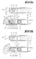
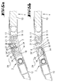
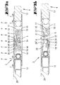
- FIG. 1 each show a partial section through cargo compartment doors 3, 4 along the section line VIIa-VIIa in Fig. 1, the section line at the level of a Hinge part 5 runs.
- the aforementioned figures each show different closed positions of one Loading door 3, starting from Fig. 2a to Fig. 7a a closing process of the cargo space door 3 is shown and the closed position shown in Fig.7a at the same time the position of the cargo hold door 3 shown in FIG. 1 corresponds.
- the cargo space doors 3, 4 each have an edge profile 10, 11, to which a door leaf 12, 13 connects.
- the hinge part 5 is two parallel Rotation axes 14, 15 rotatable, of which the rotation axis 14 the cargo space door 3 and the axis of rotation 15 of the neighboring Load compartment door 4 are assigned.
- the rotation axis 14 the cargo space door 3 and the axis of rotation 15 of the neighboring Load compartment door 4 are assigned.
- Fig. 7a and 7b show the closed position Cargo doors 3 and 4 facing the cargo space interior walls 20 and 21 and hinge-side end walls 22 and 23 on.
- Fig. 2a is further shown that an overlap wall on the inner wall 20 9 is attached. This is as an extruded profile made of an aluminum material.
- the overlap wall 9 has one Fastening section 25 on which they with a Rivets 26 attached to the inner wall 20 of the edge profile 10 is.
- the overlap wall 9 has a total essentially T-shaped configuration further an overlap portion 27. This owns a recess in which an extruded profile System strip 28 used from polyamide and is held in it.
- the overlapping wall 9 and the plant bar 28 extend perpendicular to the plane of the drawing continuously and essentially over the entire longitudinal extent the hinge-side edge of the load compartment door 3 away.
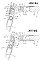
- FIG. 2b shows that on the load compartment door 3 in the area of the hinge side End wall 22 a cam 8 is arranged and that the Cam has an edge surface 31 which in one to the hinge-side end wall 22 perpendicular direction protrudes beyond the end wall 22.
- the section line VIIb-VIIb runs, which determines the sectional plane of FIGS. 2b to 11b, immediately above the loading floor and with respect to the Load compartment door 3 between a lower end of the overlapping wall 9 and an upper end of an adjoining one Nockens 8. Accordingly, the hinge part 5 in 2b to 11b in dashed lines only for Illustration drawn.
- the cam 8 engages the cross-section of the plane of the drawing with a positive fit Projections 32, 33 in associated recesses 34, 35 of the edge profile 10.
- the cam 8 extends in the drawn embodiment in that lower longitudinal section of the edge profile 10, in which a Overlap with the guide surface 29 laterally below of the cargo compartment floor 7.
- a cam 8 can be combined in an upper overlap area (above the door opening) depending on the configuration, there is also a continuous arrangement conceivable.
- a sealing element 36 the hinge-side end wall 22 attached.
- the sealing element 36 has three sealing lips 38, which overlap when the cargo compartment doors are closed extend a door gap 39, a sealing System against the hinge-side end wall 23 of the another hold door 4 is done.
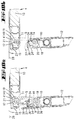
- 3a to 7a and 3b to 7b show more Sectional views of the cargo space doors 3, 4, with a Closing process of the loading space door opened in FIGS. 2a, 2b 3 shown in different angular positions becomes.
- FIGS. 2a, 2b there is a twist of the hinge part 5 about the axis of rotation 14 through the System against the flat spring 30 difficult, so that at a closing movement of the load compartment door 3 initially only a rotation of the hinge part 5 about the axis of rotation 15 takes place.
- 3a, 3b Position of the cargo space door 3 is due to the closing movement to abut the edge surface 31 of the cam 8 against the guide surface 29 on the side of the loading floor 7, a lateral shift is possible.
- a further closing movement of the cargo space door 3 therefore leads as shown in the following figures, to a Rotation of the hinge part 5 about both axes of rotation 14 and 15.
- FIGS. 4a to 7a occurs the sealing element 36 in the door gap 39, wherein a sealing contact of the sealing lips 38 on the end wall 23 takes place.
- FIG. 7a there is an installation in FIG. 7a the contact strip 28 against the inner wall 21 of the load compartment door 4 reached.
- FIGS. 6a and 7a is by the support of the Contact bar 28 on the inner wall 21 at the same time an alignment or leveling of the inner walls 20 and 21 reached.
- the symbolically indicated internal pressure P through a bulk material is evenly supported by the support the cargo doors 3 and 4 distributed.
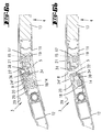
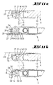
- FIGS. 8a to 11a show a partial section along the section line VIIa-VIIa
- FIGS. 8b to 11b show a partial section along the section line VIIb-VIIb in Fig. 1, with the figures again Distinguish different positions of the load compartment door 3.
- the closed position of the cargo compartment doors is in the 8a to 11a and 8b to 11b an opening process of Cargo door 3 with gradually increasing opening angle shown.
- Fig. 8b to 11b clearly shows that by the on the non-circular axle body 16 adjacent flat spring 30 initially a sole Rotation of the hinge part 5 about the axis of rotation 15 takes place.
- FIG. 8b to 11b clearly shows that by the on the non-circular axle body 16 adjacent flat spring 30 initially a sole Rotation of the hinge part 5 about the axis of rotation 15 takes place.
Landscapes
- Engineering & Computer Science (AREA)
- Mechanical Engineering (AREA)
- Wing Frames And Configurations (AREA)
- Seal Device For Vehicle (AREA)
Applications Claiming Priority (2)
| Application Number | Priority Date | Filing Date | Title |
|---|---|---|---|
| DE20008656U DE20008656U1 (de) | 2000-05-13 | 2000-05-13 | Schüttgutabweiser |
| DE20008656U | 2000-05-13 |
Publications (2)
| Publication Number | Publication Date |
|---|---|
| EP1153779A2 true EP1153779A2 (fr) | 2001-11-14 |
| EP1153779A3 EP1153779A3 (fr) | 2002-11-13 |
Family
ID=7941494
Family Applications (1)
| Application Number | Title | Priority Date | Filing Date |
|---|---|---|---|
| EP01111044A Withdrawn EP1153779A3 (fr) | 2000-05-13 | 2001-05-08 | Barrière pour éviter la pénétration de granulat dans le montant d'une porte de la cale |
Country Status (2)
| Country | Link |
|---|---|
| EP (1) | EP1153779A3 (fr) |
| DE (1) | DE20008656U1 (fr) |
Cited By (3)
| Publication number | Priority date | Publication date | Assignee | Title |
|---|---|---|---|---|
| FR2845112A1 (fr) * | 2002-09-26 | 2004-04-02 | S M T C | Charniere invisible, du type a deux axes relies par un maillon, pour volet abattant de table par exemple |
| EP1538291A1 (fr) * | 2003-12-04 | 2005-06-08 | Joachim Fischbach | Dispositif de support amovible d'un élément plan et son utilisation |
| US20180058109A1 (en) * | 2015-06-17 | 2018-03-01 | Scania Cv Ab | Door locking device for locking a vehicle door |
Citations (2)
| Publication number | Priority date | Publication date | Assignee | Title |
|---|---|---|---|---|
| EP0698515A2 (fr) | 1994-08-26 | 1996-02-28 | Pwp Sa | Porte de chargement pour par example une caisse d'un camion |
| EP0976594A1 (fr) | 1998-07-27 | 2000-02-02 | Pwp Sa | Porte de chargement |
Family Cites Families (5)
| Publication number | Priority date | Publication date | Assignee | Title |
|---|---|---|---|---|
| US1405485A (en) * | 1921-05-18 | 1922-02-07 | Thomas J Callery | Freight-car-closing device |
| GB2100780B (en) * | 1981-07-03 | 1984-08-01 | Alan Whillock | Seal for sliding doors |
| FR2572124A1 (fr) * | 1984-10-18 | 1986-04-25 | Denece Yves | Systeme de securite pour porte formant protection contre le pincement |
| DE8816879U1 (de) * | 1987-07-20 | 1991-02-21 | Wenger, Peter, Payerne | Lagerungselement |
| DE3741844A1 (de) * | 1987-12-10 | 1989-08-17 | Vaw Ver Aluminium Werke Ag | Gelenkverbindung aus mindestens zwei strangpressprofilen |
-
2000
- 2000-05-13 DE DE20008656U patent/DE20008656U1/de not_active Expired - Lifetime
-
2001
- 2001-05-08 EP EP01111044A patent/EP1153779A3/fr not_active Withdrawn
Patent Citations (2)
| Publication number | Priority date | Publication date | Assignee | Title |
|---|---|---|---|---|
| EP0698515A2 (fr) | 1994-08-26 | 1996-02-28 | Pwp Sa | Porte de chargement pour par example une caisse d'un camion |
| EP0976594A1 (fr) | 1998-07-27 | 2000-02-02 | Pwp Sa | Porte de chargement |
Cited By (4)
| Publication number | Priority date | Publication date | Assignee | Title |
|---|---|---|---|---|
| FR2845112A1 (fr) * | 2002-09-26 | 2004-04-02 | S M T C | Charniere invisible, du type a deux axes relies par un maillon, pour volet abattant de table par exemple |
| EP1538291A1 (fr) * | 2003-12-04 | 2005-06-08 | Joachim Fischbach | Dispositif de support amovible d'un élément plan et son utilisation |
| US20180058109A1 (en) * | 2015-06-17 | 2018-03-01 | Scania Cv Ab | Door locking device for locking a vehicle door |
| US11015374B2 (en) * | 2015-06-17 | 2021-05-25 | Scania Cv Ab | Door locking device for locking a vehicle door |
Also Published As
| Publication number | Publication date |
|---|---|
| EP1153779A3 (fr) | 2002-11-13 |
| DE20008656U1 (de) | 2001-09-27 |
Similar Documents
| Publication | Publication Date | Title |
|---|---|---|
| DE69715591T2 (de) | Justierbarer Doppelfunktions-Anschlag für eine Kraftfahrzeug-Schiebetür | |
| DE60200510T2 (de) | Führungsschienenaufbau für ein Kipptor | |
| DE4240416B4 (de) | Versteifungsanordnung für einen Kraftfahrzeug-Aufbau mit einem Türträger | |
| DE10155220C1 (de) | Türanordnung für Kraftfahrzeuge | |
| DE69623626T2 (de) | Türsystem | |
| DE3532318C1 (de) | Schiebedach fuer Kraftfahrzeuge | |
| EP0698515B1 (fr) | Porte de chargement pour par example une caisse d'un camion | |
| DE2934150C2 (fr) | ||
| DE10256131A1 (de) | Kraftfahrzeugtür | |
| DE102013007876B4 (de) | Fahrzeugtüranordnung | |
| EP1346879B1 (fr) | Profilé pour un longeron d'un véhicule | |
| DE10041360A1 (de) | Hecktür für ein Kraftfahrzeug | |
| EP0092238A1 (fr) | Porte repliable | |
| EP1153779A2 (fr) | Barrière pour éviter la pénétration de granulat dans le montant d'une porte de la cale | |
| EP0338519B1 (fr) | Charnière à double joint pour la connection d'un panneau de porte à la paroi fixe d'un chassis de voiture utilitaire | |
| DE19834700B4 (de) | Vorrichtung zum Verschließen einer Wandöffnung | |
| DE19946666C2 (de) | Scharnieranordnung für eine Tür eines Kraftfahrzeugs | |
| DE10115096C1 (de) | Toranlage mit einem entlang mindestens eines ortsfesten Rollenbocks geführten Tragprofil | |
| DE102012218887B4 (de) | Schließstück für ein Fenster, eine Tür oder dergleichen | |
| DE102011056233A1 (de) | Trägerbauteil für einen Kraftfahrzeug-Fensterheber mit Versteifungsstruktur | |
| WO2002018735A1 (fr) | Fixation de porte | |
| DE3203276A1 (de) | Scharnieranordnung fuer eine tuer, insbesondere eine kraftfahrzeugtuer | |
| EP1516763B1 (fr) | Structure de caisse | |
| DE60216223T2 (de) | Motorisch betriebene Schliesseinrichtung einer Öffnung in einem Fahrzeug und zugehöriges Fahrzeug | |
| EP4386164B1 (fr) | Agencement d'ouvrant |
Legal Events
| Date | Code | Title | Description |
|---|---|---|---|
| PUAI | Public reference made under article 153(3) epc to a published international application that has entered the european phase |
Free format text: ORIGINAL CODE: 0009012 |
|
| AK | Designated contracting states |
Kind code of ref document: A2 Designated state(s): AT BE CH CY DE DK ES FI FR GB GR IE IT LI LU MC NL PT SE TR |
|
| AX | Request for extension of the european patent |
Free format text: AL;LT;LV;MK;RO;SI |
|
| PUAL | Search report despatched |
Free format text: ORIGINAL CODE: 0009013 |
|
| AK | Designated contracting states |
Kind code of ref document: A3 Designated state(s): AT BE CH CY DE DK ES FI FR GB GR IE IT LI LU MC NL PT SE TR |
|
| AX | Request for extension of the european patent |
Free format text: AL;LT;LV;MK;RO;SI |
|
| RIC1 | Information provided on ipc code assigned before grant |
Free format text: 7B 60J 5/04 A, 7B 62D 33/04 B, 7E 05D 3/06 B, 7B 60J 5/06 B |
|
| 17P | Request for examination filed |
Effective date: 20030508 |
|
| AKX | Designation fees paid |
Designated state(s): AT BE CH CY DE DK ES FI FR GB GR IE IT LI LU MC NL PT SE TR |
|
| 17Q | First examination report despatched |
Effective date: 20030826 |
|
| STAA | Information on the status of an ep patent application or granted ep patent |
Free format text: STATUS: THE APPLICATION IS DEEMED TO BE WITHDRAWN |
|
| 18D | Application deemed to be withdrawn |
Effective date: 20051201 |