EP1153805A2 - Sicherheitseinrichtung für die Lagerung von Pedalen - Google Patents
Sicherheitseinrichtung für die Lagerung von Pedalen Download PDFInfo
- Publication number
- EP1153805A2 EP1153805A2 EP01109739A EP01109739A EP1153805A2 EP 1153805 A2 EP1153805 A2 EP 1153805A2 EP 01109739 A EP01109739 A EP 01109739A EP 01109739 A EP01109739 A EP 01109739A EP 1153805 A2 EP1153805 A2 EP 1153805A2
- Authority
- EP
- European Patent Office
- Prior art keywords
- pedal
- safety device
- collision
- bearing block
- guide
- Prior art date
- Legal status (The legal status is an assumption and is not a legal conclusion. Google has not performed a legal analysis and makes no representation as to the accuracy of the status listed.)
- Granted
Links
- 230000001960 triggered effect Effects 0.000 claims description 6
- 239000007921 spray Substances 0.000 abstract description 2
- 230000007246 mechanism Effects 0.000 description 11
- NJPPVKZQTLUDBO-UHFFFAOYSA-N novaluron Chemical compound C1=C(Cl)C(OC(F)(F)C(OC(F)(F)F)F)=CC=C1NC(=O)NC(=O)C1=C(F)C=CC=C1F NJPPVKZQTLUDBO-UHFFFAOYSA-N 0.000 description 4
- 230000006735 deficit Effects 0.000 description 3
- 238000004519 manufacturing process Methods 0.000 description 3
- 208000027418 Wounds and injury Diseases 0.000 description 2
- 238000010276 construction Methods 0.000 description 2
- 230000006378 damage Effects 0.000 description 2
- 208000014674 injury Diseases 0.000 description 2
- 208000017899 Foot injury Diseases 0.000 description 1
- 229910000831 Steel Inorganic materials 0.000 description 1
- 230000005540 biological transmission Effects 0.000 description 1
- 238000006073 displacement reaction Methods 0.000 description 1
- 238000005259 measurement Methods 0.000 description 1
- 238000000034 method Methods 0.000 description 1
- 230000000717 retained effect Effects 0.000 description 1
- 238000005507 spraying Methods 0.000 description 1
- 239000010959 steel Substances 0.000 description 1
- 239000000725 suspension Substances 0.000 description 1
Images


Classifications
-
- G—PHYSICS
- G05—CONTROLLING; REGULATING
- G05G—CONTROL DEVICES OR SYSTEMS INSOFAR AS CHARACTERISED BY MECHANICAL FEATURES ONLY
- G05G1/00—Controlling members, e.g. knobs or handles; Assemblies or arrangements thereof; Indicating position of controlling members
- G05G1/30—Controlling members actuated by foot
- G05G1/32—Controlling members actuated by foot with means to prevent injury
- G05G1/327—Controlling members actuated by foot with means to prevent injury means disconnecting the pedal from its hinge or support, e.g. by breaking or bending the support
-
- B—PERFORMING OPERATIONS; TRANSPORTING
- B60—VEHICLES IN GENERAL
- B60R—VEHICLES, VEHICLE FITTINGS, OR VEHICLE PARTS, NOT OTHERWISE PROVIDED FOR
- B60R21/00—Arrangements or fittings on vehicles for protecting or preventing injuries to occupants or pedestrians in case of accidents or other traffic risks
- B60R21/02—Occupant safety arrangements or fittings, e.g. crash pads
- B60R21/09—Control elements or operating handles movable from an operative to an out-of-the way position, e.g. pedals, switch knobs, window cranks
-
- B—PERFORMING OPERATIONS; TRANSPORTING
- B60—VEHICLES IN GENERAL
- B60T—VEHICLE BRAKE CONTROL SYSTEMS OR PARTS THEREOF; BRAKE CONTROL SYSTEMS OR PARTS THEREOF, IN GENERAL; ARRANGEMENT OF BRAKING ELEMENTS ON VEHICLES IN GENERAL; PORTABLE DEVICES FOR PREVENTING UNWANTED MOVEMENT OF VEHICLES; VEHICLE MODIFICATIONS TO FACILITATE COOLING OF BRAKES
- B60T7/00—Brake-action initiating means
- B60T7/02—Brake-action initiating means for personal initiation
- B60T7/04—Brake-action initiating means for personal initiation foot actuated
- B60T7/06—Disposition of pedal
- B60T7/065—Disposition of pedal with means to prevent injuries in case of collision
-
- Y—GENERAL TAGGING OF NEW TECHNOLOGICAL DEVELOPMENTS; GENERAL TAGGING OF CROSS-SECTIONAL TECHNOLOGIES SPANNING OVER SEVERAL SECTIONS OF THE IPC; TECHNICAL SUBJECTS COVERED BY FORMER USPC CROSS-REFERENCE ART COLLECTIONS [XRACs] AND DIGESTS
- Y10—TECHNICAL SUBJECTS COVERED BY FORMER USPC
- Y10T—TECHNICAL SUBJECTS COVERED BY FORMER US CLASSIFICATION
- Y10T74/00—Machine element or mechanism
- Y10T74/20—Control lever and linkage systems
- Y10T74/20528—Foot operated
-
- Y—GENERAL TAGGING OF NEW TECHNOLOGICAL DEVELOPMENTS; GENERAL TAGGING OF CROSS-SECTIONAL TECHNOLOGIES SPANNING OVER SEVERAL SECTIONS OF THE IPC; TECHNICAL SUBJECTS COVERED BY FORMER USPC CROSS-REFERENCE ART COLLECTIONS [XRACs] AND DIGESTS
- Y10—TECHNICAL SUBJECTS COVERED BY FORMER USPC
- Y10T—TECHNICAL SUBJECTS COVERED BY FORMER US CLASSIFICATION
- Y10T74/00—Machine element or mechanism
- Y10T74/20—Control lever and linkage systems
- Y10T74/20528—Foot operated
- Y10T74/20534—Accelerator
-
- Y—GENERAL TAGGING OF NEW TECHNOLOGICAL DEVELOPMENTS; GENERAL TAGGING OF CROSS-SECTIONAL TECHNOLOGIES SPANNING OVER SEVERAL SECTIONS OF THE IPC; TECHNICAL SUBJECTS COVERED BY FORMER USPC CROSS-REFERENCE ART COLLECTIONS [XRACs] AND DIGESTS
- Y10—TECHNICAL SUBJECTS COVERED BY FORMER USPC
- Y10T—TECHNICAL SUBJECTS COVERED BY FORMER US CLASSIFICATION
- Y10T74/00—Machine element or mechanism
- Y10T74/20—Control lever and linkage systems
- Y10T74/20576—Elements
- Y10T74/20888—Pedals
Definitions
- the present invention relates to a safety device for storing pedals in motor vehicles according to the preamble of claim 1.
- the pedals are used to operate the vehicle, i.e. the Foot lever mechanism, which occurs in a frontal collision of the vehicle noticeable wall area deforming into the passenger compartment, this bulkhead or transverse wall attached.
- the foot pedal mechanism would be hinged to it Pedals also in the event of a frontal collision of the vehicle be moved deeper into the passenger compartment and thereby the risk of injury to the vehicle driver would be considerable increase.
- a safety foot lever mechanism such to design that the pedals of the foot lever mechanism swivel are mounted on a pedal axle, which in turn basically one that extends at least approximately vertically slot-shaped link guide of the bearing block is held and in the event of a collision-related shifting of the bearing block towards the cross member by an attacking and with it Interacting pulleys interacting rope or chain-shaped Power transmission link in the link guide automatically is pulled up.
- This will become the pedal or pedals from the footwell of the vehicle upwards for the driver safe areas of the passenger compartment are shifted, whereby the pedal and the push rod automatically decouples become.
- This is also a very constructive one elaborate arrangement leading to undesirably high manufacturing costs leads.
- the European patent application EP 0 827 874 also discloses an arrangement in which in the event of a head-on collision the pedal axle can be released from its storage and thus the pedal axle is released from the pedestal.
- a foot pedal mechanism is also explained in DE 195 01 680 PS, in which in a head-on collision the pedal bearing axis is fully released. The pedal is then only with the Brake or clutch cable or the like connected and can otherwise move freely with respect to the surrounding foot space, so that in an accident the feet and / or legs of the Driver can avoid.
- DE 195 01 859 A1 also describes a safety arrangement known for a motor vehicle with a pedal mechanism, in which a Bearing bracket of the pedal mechanism attached to a support element which is of a front bounding the passenger compartment Bulkhead spaced and decoupled.
- the support element should be in one position in the vehicle, that is not directly affected by a vehicle accident and therefore do not immediately continue pedaling in the event of a frontal accident moves into the passenger compartment.
- the pedal unit can even do so in the event of a vehicle accident be moved away from the driver, reducing the risk of injury the driver is reduced.
- the operating rod is not in a vehicle accident safe and can not effectively injure the driver prevent since the entire arrangement in the event of a vehicle accident occurring deformations and the the intended mode of action cannot be guaranteed can. Furthermore, by a spaced arrangement of the bearing block a relatively large amount of space is required.
- German published documents DE 196 52 014 and DE 197 37 114 again disclose a pedal bearing for a motor vehicle, which should be provided such that the pedal at a frontal accident can be decoupled from its storage can.
- the safety device for storage of pedals in motor vehicles with one in the range of one in the event of a head-on collision of the vehicle in a passenger compartment deforming wall area of a spray or Transverse wall arranged bearing block, in which at least one pedal axis one that swivels on a push rod Pedal, in particular a brake pedal, is supported is characterized in that the pedal axis in the bearing block in one supported substantially horizontally extending guide is, the guide at least in the horizontal direction each has limitations and the pedal axis during the Normal operation in a front viewed in the forward direction Position of the guide is fixed and this fixation a frontal collision is canceled.
- a head-on collision like the one below Often mentioned here, include any type of collision should, in the deformations in the frontal area of the vehicle may occur. This means that it is, for example can also be secondary frontal collisions and does not necessarily have to be primary frontal collisions.
- Safety device is designed such that the fixation by the relative movement of the pedestal its spatial position even in a head-on collision essentially unchanged vehicle part canceled becomes.
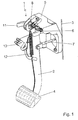
- a safety device 1 is shown in FIG their normal position, i.e. without a head-on collision took place, shown.
- Such a safety device is used for storing pedals 2 in motor vehicles, with a bearing block 5, which occurs in a frontal collision of the Vehicle deforming significantly into a passenger compartment Wall area of a bulkhead or transverse wall 3 is arranged.
- a pedal axis 6 at least one on one Push rod 7 acting, pivotable pedal 2, in particular a brake pedal with a tread plate 4, supported.
- FIGS. 1 and 2 12 there is also a return spring in FIGS. 1 and 2 12, which serves to release the brake, i.e. after this the load on the driver's foot taken from pedal 2 to return pedal 2 to its normal position and so on to exert no pressure on the push rod 7. If the brake is activated, the brake light switch 13 activated the brake light.
- FIG 3 is an arrangement corresponding to FIGS. 1 and 2 the safety device 1 in its normal position shown a side view.
- the Position of the pedal axis 6 can be easily recognized.
- the fixation 11 can, according to a preferred embodiment of the invention, but this is not shown in the figures is, by the relative movement of the bearing block 5 to one his spatial position even in a head-on collision essentially unchanged vehicle part canceled become. So that means that the fixation on such essentially maintain its position in a head-on collision Vehicle part is fastened and is thereby lifted, that the bearing block 5 moves and the fixed part does not.
- FIG. 3 A representation corresponding to FIG. 3, but with the Position of the pedal 2 is shown after the fixation 11th 4 shows.
- the fixation 11, not shown in FIGS. 3 and 4 is canceled in the event of a head-on collision, causing the Pedal axis 6 in the guide in the bearing block 8 in the forward direction seen running backwards.
- pedal 2 forward.
- the run ahead the pedal 2 can be done without power.
- the movement of the pedal 2 after removing the fixation 11 after one Head-on collision is represented by the arrows in FIG. 4.
- the pedal 2 is now no longer fixed, and therefore there can be no constrictions in the feet and jamming of the vehicle occupants.
- the pedal 2 cannot simply be uncontrolled run into the passenger compartment and thus cause impairments of the vehicle occupant.
- this is its spatial position in a head-on collision essentially unchanged vehicle part Body-fixed vehicle part.
- This vehicle body-fixed vehicle part for example be a cross member or a dashboard support.
- At Both parts of the vehicle are in the forward direction seen behind the vehicle parts arranged on the pedal 2, which is usually essentially the case in a head-on collision are vehicle-proof or at least only with very strong ones Accidents are affected.
- FIGS. 1 and 2 it at least shows Guide 8 extending in the horizontal direction in the bearing block 5 essentially the shape of a rectangle. As well but it could also be designed as an elongated hole.
- the length of the guide 8 for example the The length of the elongated hole or rectangle can, as already described that was available in a head-on collision Pedal travel can be changed forward and so to the respective Vehicle conditions are adjusted.
- Has a design of the guide 8 in the form of an elongated hole turned out to be advantageous because they were created very easily can be and also very easy again reformed into a form corresponding to the state of the art can be, if a safety device 1 according to of the present invention is no longer desired because then, for example, it can simply be reduced in size again by filling it up and then again in the shape of a usual bore.
- the Advance of the pedal axis 6 in the guide 8 of the bearing block 5 seen in the forward driving direction backwards in a head-on collision also supported by an additional spring be so that the pedal 2 is actually backwards moved as soon as the fixation 11 was released.
- Such Embodiment has proven to be particularly advantageous if other units of the vehicle trigger correctly monitor the safety device 1 according to the invention and only then can see that lifting the fixation 11 has taken place when the pedal 2 is in the Guide 8 in the bearing block 5 actually in the forward direction seen moving backwards.
- FIG. 1 and also in FIG. 2 has a safety device 1 according to the invention Fixing 11 of the pedal axis 6 in such a way that by at the a head-on collision essentially maintaining its position Vehicle part release lever 11 are provided. So can this release lever 11, for example, a stop on the Have body.
- Pedal bracket 5 now moves in a head-on collision by the deformation of the bulkhead or transverse wall 3 in the direction of the vehicle interior, it can be used as a release lever trained fixation 11 of the pedal axis 6 triggered thereby be that the vehicle part that its spatial location essentially unchanged even in a head-on collision maintains, moved relative to the pedal bracket 5.
- This will the fixation 11, which preferably represent release levers, solved. Due to the relative movement described, the a release lever articulated in the vehicle, for example can be folded away in a simple manner.
- the fixation 11 can also be operated by an auxiliary power to be triggered. It could also be provided be that a sensor measures a frontal accident, and then over hydraulic, pneumatic or pyrotechnic means Fixation 11 is released.
- the brake rod 7 is not released from the pedal 2, and also the pedal axis 6 at least some storage, if not fixed at a fixed point, has, it is also possible to the brake rod 7 to exert a force. This may not be the case always completely possible, at least the possibility of one Partial braking is still retained.
- the safety device 1 If there is a frontal collision in a vehicle, would the safety device 1 according to the present invention to be activated. After this head-on collision, it would be conceivable that the vehicle hurled into the opposite lane is on a lane area that is still on a flow of traffic takes place, or to get onto such threatens or could get on pedestrian paths. There it can be very important that the vehicle despite the triggering the safety device 1, which jams the driver's foot prevented, can still be braked and the vehicle can be braked even before it, for example the oncoming lane continues to roll. This can, under certain circumstances a second collision can be prevented.
- the present safety device 1 according to the invention has have proven to be particularly advantageous because a very simple constructive design high level of safety for vehicle occupants and outsiders Offers accident victims.
- the safety device 1 can according to the present invention be designed such that the pedal bracket 5, such also previously in pedal works of the prior art, usually is made of plastic. This allows the so far used innovative lightweight construction of the pedal bracket 5 also used in a safety device 1 according to the invention be, which in addition to a simple construction no unnecessary increases in the weight of the vehicle and thus the operating costs through the safety device 1 the Episode are.
- FIG. 5 is a top view of an illustration the safety device 1 shown in FIG. 2, a release lever 11 is shown on one side, the the slot 8 closes. The other side is without a trigger 11 illustrated and only with the Pedalagerache 6 in the Elongated hole 8.
- the release lever 11 is, as shown in Fig. 5 can be seen in its closing the slot 8 Position so that it faces the passenger compartment seen in front of the pedal bearing axis 6 is arranged. Find now triggering of the lever 11 by deformation of the end wall 3 instead, then the lever 11 is pulled out and thereby the Wall area 14 canceled. Thus, the strength of the Wall area 14 changes the triggering force of the fixation 11 become.
Landscapes
- Engineering & Computer Science (AREA)
- Mechanical Engineering (AREA)
- Physics & Mathematics (AREA)
- General Physics & Mathematics (AREA)
- Automation & Control Theory (AREA)
- Transportation (AREA)
- Mechanical Control Devices (AREA)
- Braking Elements And Transmission Devices (AREA)
Abstract
Description
- Fig. 1
- eine dreidimensionale Ansicht einer erfindungsgemäßen Sicherheitseinrichtung in ihrer Normalstellung;
- Fig. 2
- einen vergrößerten Ausschnitt des Bereichs der Lagerung der Pedalachse aus Fig. 1 in einer teilweise geschnittenen Ansicht;
- Fig. 3
- eine seitliche Darstellung der erfindungsgemäßen Sicherheitseinrichtung in ihrer Normalstellung;
- Fig. 4
- eine Darstellung entsprechend Fig. 3, wobei das Pedal in einer Stellung nach Auslösung der erfindungsgemäßen Sicherheitseinrichtung gezeigt ist; und
- Fig. 5
- eine Draufsicht auf eine Darstellung der Sicherheitseinrichtung entsprechend der Fig. 2, wobei auf einer Seite ein Auslösehebel dargestellt ist und auf der anderen Seite nicht.
Claims (12)
- Sicherheitseinrichtung für die Lagerung von Pedalen in Kraftfahrzeugen, insbesondere Personenkraftfahrzeugen, mit einem Lagerbock, der in einem sich bei einer Frontalkollision des Fahrzeugs spürbar in einen Fahrgastraum hinein verformenden Wandbereich einer Spritz- oder Querwand angeordnet ist, wobei in dem Lagerbock eine Pedalachse mindestens eines auf eine Druckstange einwirkenden, schwenkbaren Pedals, insbesondere eines Bremspedals, gehaltert ist,
dadurch gekennzeichnet, daß die Pedalachse (6) im Lagerbock (5) in einer sich zumindest im wesentlichen horizontal erstreckenden Führung (8) gehaltert ist, wobei die Führung (8) in horizontaler Richtung jeweils Begrenzungen (9) aufweist; und
die Pedalachse (6) während des Normalbetriebes in einer in Vorwärtsfahrtrichtung gesehen vorderen Position der Führung (8) fixiert ist und diese Fixierung (11) bei einer Frontalkollision aufgehoben wird. - Sicherheitseinrichtung nach Anspruch 1,
dadurch gekennzeichnet, daß die Fixierung (11) durch eine relative Bewegung des Lagerbockes (5) zu einem seine räumliche Lage auch bei einer Frontalkollision im wesentlichen unverändert beibehaltenden Fahrzeugteil aufgehoben wird. - Sicherheitseinrichtung nach Anspruch 1,
dadurch gekennzeichnet, daß das seine räumliche Lage bei einer Frontalkollision im wesentlichen unverändert beibehaltende Fahrzeugteil karosseriefest ist. - Sicherheitseinrichtung nach Anspruch 3,
dadurch gekennzeichnet, daß das karosseriefeste Fahrzeugteil ein Querträger ist. - Sicherheitseinrichtung nach Anspruch 3,
dadurch gekennzeichnet, daß das karosseriefeste Fahrzeugteil ein Armaturentafelträger ist. - Sicherheitseinrichtung nach Anspruch 1,
dadurch gekennzeichnet, daß die sich zumindest im wesentlichen horizontal erstrekkende Führung (8) im Lagerbock (5) im wesentlichen die Form eines Langloches aufweist. - Sicherheitseinrichtung nach Anspruch 1,
dadurch gekennzeichnet, daß ein Bewegen der Pedalachse (6) in der Führung (8) in Vorwärtsfahrtrichtung gesehen nach hinten bei einer Frontalkollision durch eine Feder unterstützt wird. - Sicherheitseinrichtung nach Anspruch 1,
dadurch gekennzeichnet, daß die Fixierung (11) der Pedalachse (6) durch an dem bei einer Frontalkollision im wesentlichen seine Position beibehaltenden Fahrzeugteil befestigte Auslösehebel erfolgt. - Sicherheitseinrichtung nach Anspruch 8,
dadurch gekennzeichnet, daß die Fixierung (11) durch die relative Bewegung des Pedallagerbockes (5) zum bei einer Frontalkollision im wesentlichen seine Position beibehaltenden Fahrzeugteil ausgelöst werden. - Sicherheitseinrichtung nach Anspruch 1,
dadurch gekennzeichnet, daß die Fixierung (11) hilfskraftbetätigt ausgelöst wird. - Sicherheitseinrichtung nach Anspruch 1,
dadurch gekennzeichnet, daß der Pedallagerbock (5) aus Kunststoff ausgebildet ist. - Sicherheitseinrichtung nach Anspruch 1,
dadurch gekennzeichnet, daß das Pedal (2) als ein Zweischalenpedal ausgebildet ist.
Applications Claiming Priority (2)
| Application Number | Priority Date | Filing Date | Title |
|---|---|---|---|
| DE10022813A DE10022813C5 (de) | 2000-05-10 | 2000-05-10 | Sicherheitseinrichtung für die Lagerung von Pedalen |
| DE10022813 | 2000-05-10 |
Publications (3)
| Publication Number | Publication Date |
|---|---|
| EP1153805A2 true EP1153805A2 (de) | 2001-11-14 |
| EP1153805A3 EP1153805A3 (de) | 2004-01-07 |
| EP1153805B1 EP1153805B1 (de) | 2008-01-16 |
Family
ID=7641475
Family Applications (1)
| Application Number | Title | Priority Date | Filing Date |
|---|---|---|---|
| EP01109739A Expired - Lifetime EP1153805B1 (de) | 2000-05-10 | 2001-04-20 | Sicherheitseinrichtung für die Lagerung von Pedalen |
Country Status (5)
| Country | Link |
|---|---|
| US (1) | US6786109B2 (de) |
| EP (1) | EP1153805B1 (de) |
| JP (1) | JP2002002460A (de) |
| DE (2) | DE10022813C5 (de) |
| ES (1) | ES2299448T3 (de) |
Cited By (2)
| Publication number | Priority date | Publication date | Assignee | Title |
|---|---|---|---|---|
| EP1557330A3 (de) * | 2004-01-20 | 2005-12-21 | Batz, S. Coop. | Pedal mit Antikollisionssicherheitsmechanismus |
| CN102205835A (zh) * | 2010-03-31 | 2011-10-05 | 本田技研工业株式会社 | 踏板装置 |
Families Citing this family (24)
| Publication number | Priority date | Publication date | Assignee | Title |
|---|---|---|---|---|
| SE518099C2 (sv) | 1997-11-21 | 2002-08-27 | Claes Johansson Automotive Ab | Inställbart pedalställ för ett fordon |
| FR2832969B1 (fr) * | 2001-11-30 | 2004-01-02 | Renault | Dispositif de montage d'une pedale sur un vehicule |
| DE10222106A1 (de) | 2002-05-17 | 2004-01-22 | Fico Cables, S.A., Rubi | Pedalsicherheitssystem |
| US7744645B2 (en) * | 2003-09-29 | 2010-06-29 | Medtronic Vascular, Inc. | Laminated drug-polymer coated stent with dipped and cured layers |
| DE10354668B4 (de) * | 2003-11-22 | 2007-02-22 | EDSCHA Betätigungssysteme GmbH | Pedallager |
| SE527696C2 (sv) * | 2004-01-26 | 2006-05-16 | Teleflex Automotive Sweden Ab | Anordning för pedalställ |
| CA2495351A1 (en) * | 2004-01-29 | 2005-07-29 | Intier Automotive Closures Inc. | Variable ratio brake pedal |
| US20080047386A1 (en) * | 2006-08-07 | 2008-02-28 | Ridgway Jason R | Automotive foot pedal assembly |
| ATE552547T1 (de) * | 2008-01-08 | 2012-04-15 | Gm Global Tech Operations Inc | Sicherheitspedalsystem |
| US7987743B2 (en) * | 2008-12-19 | 2011-08-02 | Ventra Group, Inc. | Positive release crash pedal mechanism |
| FR2944115B1 (fr) | 2009-04-07 | 2015-06-05 | Coutier Moulage Gen Ind | Pedale de vehicule automobile avec dispositif de mise en securite. |
| DE102009034783B4 (de) | 2009-07-25 | 2017-07-13 | Volkswagen Ag | Fußhebelwerk an Kraftfahrzeugen |
| KR101730515B1 (ko) * | 2009-08-18 | 2017-04-26 | 케이에스알 아이피 홀딩스 엘엘씨. | 비접촉 센서를 구비한 브레이크 페달 어셈블리 |
| US8474348B2 (en) * | 2010-02-04 | 2013-07-02 | Ksr Technologies Co. | Pedal assembly for electronic braking system |
| US8806976B2 (en) | 2010-02-04 | 2014-08-19 | Ksr Technologies Co. | Brake pedal assembly having non-contacting sensor |
| DE102010025566A1 (de) * | 2010-06-29 | 2011-12-29 | Gm Global Technology Operations Llc (N.D.Ges.D. Staates Delaware) | Anordnung zum Lösen eines Fußpedals |
| EP2578454B1 (de) * | 2011-10-06 | 2014-12-10 | Volvo Car Corporation | Sicherheitsanordnung für Fahrzeugpedal |
| WO2013136166A1 (en) | 2012-03-15 | 2013-09-19 | Ksr Tecnologies Co. | Pedal assembly having a pedal arm release |
| KR101509990B1 (ko) * | 2013-11-27 | 2015-04-07 | 현대자동차주식회사 | 차량용 클러치페달의 답력 저감장치 |
| KR101526723B1 (ko) * | 2013-12-03 | 2015-06-05 | 현대자동차주식회사 | 위치 가변형 페달 |
| US9889826B2 (en) | 2014-02-19 | 2018-02-13 | Ventra Group Co. | Variable ratio brake pedal |
| DE102015208203A1 (de) * | 2015-05-04 | 2016-11-10 | Bayerische Motoren Werke Aktiengesellschaft | Pedalanordnung für ein Kraftfahrzeug und hiermit ausgestattetes Kraftfahrzeug |
| USD920860S1 (en) * | 2019-05-03 | 2021-06-01 | Ventra Group Co. | Automotive brake pedal arm |
| US11994894B2 (en) * | 2022-01-24 | 2024-05-28 | Ventra Group Co. | Pedal assembly with pyrotechnic release |
Citations (10)
| Publication number | Priority date | Publication date | Assignee | Title |
|---|---|---|---|---|
| DE4409235A1 (de) | 1993-03-31 | 1994-10-06 | Volkswagen Ag | Sicherheitsfußhebelwerk für ein Kraftfahrzeug |
| DE4409324A1 (de) | 1993-03-31 | 1994-10-06 | Volkswagen Ag | Sicherheitsfußhebelwerk für ein Kraftfahrzeug |
| DE19501859A1 (de) | 1995-01-23 | 1996-07-25 | Volkswagen Ag | Sicherheitsanordnung für ein Kraftfahrzeug |
| DE19501680A1 (de) | 1995-01-20 | 1996-08-08 | Schmidt Gmbh R | Fußhebelwerk für ein Kraftfahrzeug |
| WO1997028029A1 (en) | 1996-01-30 | 1997-08-07 | Ab Volvo | Method for activation of a safety arrangement in a vehicle |
| DE19631212C1 (de) | 1996-08-02 | 1997-12-18 | Daimler Benz Ag | Fahrpedaleinheit |
| DE19617372C1 (de) | 1996-04-30 | 1998-01-02 | Lucas Ind Plc | Pedalanordnung für ein Kraftfahrzeug |
| EP0827874A2 (de) | 1996-08-07 | 1998-03-11 | Adam Opel Ag | Anordnung zur Lagerung eines Pedals |
| DE19652014A1 (de) | 1996-12-13 | 1998-06-18 | Opel Adam Ag | Pedallagerung für ein Kraftfahrzeug |
| DE19737114A1 (de) | 1997-08-03 | 1999-05-06 | Scharwaechter Ed Gmbh | Sicherheitseinrichtung für die Lagerung von Pedalen in Kfz |
Family Cites Families (15)
| Publication number | Priority date | Publication date | Assignee | Title |
|---|---|---|---|---|
| US3388610A (en) * | 1966-05-31 | 1968-06-18 | Val R. Pyle | Brake pedal linkage |
| US3803941A (en) * | 1972-10-20 | 1974-04-16 | Yoshikawa Seisakusho Kk | Brake lever for a bicycle |
| FR2272871B1 (de) * | 1974-05-27 | 1976-12-24 | Citroen Sa | |
| US4875385A (en) * | 1986-08-18 | 1989-10-24 | Sitrin Gabriel M | Control pedal apparatus for a motor vehicle |
| US5460061A (en) * | 1993-09-17 | 1995-10-24 | Comfort Pedals, Inc. | Adjustable control pedal apparatus |
| DE19529347A1 (de) * | 1995-08-09 | 1997-02-20 | Hs Tech & Design | Vorrichtung zum Lösen der Verankerung eines Pedals vom Aufbau eines Kraftfahrzeugs |
| JP3454014B2 (ja) | 1995-08-31 | 2003-10-06 | トヨタ自動車株式会社 | 車両用ペダル支持構造 |
| JP3269372B2 (ja) | 1996-02-13 | 2002-03-25 | トヨタ自動車株式会社 | 車両用ペダル構造 |
| JPH09290714A (ja) * | 1996-04-30 | 1997-11-11 | Toyota Motor Corp | 車両用ペダル支持構造 |
| JP3454041B2 (ja) | 1996-10-08 | 2003-10-06 | スズキ株式会社 | ブレーキペダルの支持構造 |
| DE19706427A1 (de) * | 1997-02-19 | 1998-08-20 | Itt Mfg Enterprises Inc | Druckmittelspeicher |
| DE19733512C2 (de) * | 1997-08-03 | 2003-12-11 | Scharwaechter Gmbh Co Kg | Sicherheitseinrichtung |
| JP2000177546A (ja) * | 1998-12-17 | 2000-06-27 | Otsuka Koki Co Ltd | 足踏み式パーキングブレーキ装置 |
| DE19921392C2 (de) * | 1999-05-10 | 2001-08-02 | Zf Lemfoerder Metallwaren Ag | Betätigungseinrichtung für die Bremsanlage eines Kraftfahrzeuges |
| GB2353009B (en) * | 2000-04-27 | 2001-07-11 | Dura Automotive Ltd | Collapsible pedal box |
-
2000
- 2000-05-10 DE DE10022813A patent/DE10022813C5/de not_active Expired - Fee Related
-
2001
- 2001-04-20 DE DE50113488T patent/DE50113488D1/de not_active Expired - Lifetime
- 2001-04-20 EP EP01109739A patent/EP1153805B1/de not_active Expired - Lifetime
- 2001-04-20 ES ES01109739T patent/ES2299448T3/es not_active Expired - Lifetime
- 2001-05-10 US US09/852,285 patent/US6786109B2/en not_active Expired - Fee Related
- 2001-05-10 JP JP2001140755A patent/JP2002002460A/ja active Pending
Patent Citations (10)
| Publication number | Priority date | Publication date | Assignee | Title |
|---|---|---|---|---|
| DE4409235A1 (de) | 1993-03-31 | 1994-10-06 | Volkswagen Ag | Sicherheitsfußhebelwerk für ein Kraftfahrzeug |
| DE4409324A1 (de) | 1993-03-31 | 1994-10-06 | Volkswagen Ag | Sicherheitsfußhebelwerk für ein Kraftfahrzeug |
| DE19501680A1 (de) | 1995-01-20 | 1996-08-08 | Schmidt Gmbh R | Fußhebelwerk für ein Kraftfahrzeug |
| DE19501859A1 (de) | 1995-01-23 | 1996-07-25 | Volkswagen Ag | Sicherheitsanordnung für ein Kraftfahrzeug |
| WO1997028029A1 (en) | 1996-01-30 | 1997-08-07 | Ab Volvo | Method for activation of a safety arrangement in a vehicle |
| DE19617372C1 (de) | 1996-04-30 | 1998-01-02 | Lucas Ind Plc | Pedalanordnung für ein Kraftfahrzeug |
| DE19631212C1 (de) | 1996-08-02 | 1997-12-18 | Daimler Benz Ag | Fahrpedaleinheit |
| EP0827874A2 (de) | 1996-08-07 | 1998-03-11 | Adam Opel Ag | Anordnung zur Lagerung eines Pedals |
| DE19652014A1 (de) | 1996-12-13 | 1998-06-18 | Opel Adam Ag | Pedallagerung für ein Kraftfahrzeug |
| DE19737114A1 (de) | 1997-08-03 | 1999-05-06 | Scharwaechter Ed Gmbh | Sicherheitseinrichtung für die Lagerung von Pedalen in Kfz |
Cited By (3)
| Publication number | Priority date | Publication date | Assignee | Title |
|---|---|---|---|---|
| EP1557330A3 (de) * | 2004-01-20 | 2005-12-21 | Batz, S. Coop. | Pedal mit Antikollisionssicherheitsmechanismus |
| CN102205835A (zh) * | 2010-03-31 | 2011-10-05 | 本田技研工业株式会社 | 踏板装置 |
| CN102205835B (zh) * | 2010-03-31 | 2014-02-26 | 本田技研工业株式会社 | 踏板装置 |
Also Published As
| Publication number | Publication date |
|---|---|
| DE50113488D1 (de) | 2008-03-06 |
| ES2299448T3 (es) | 2008-06-01 |
| DE10022813B4 (de) | 2004-02-19 |
| EP1153805B1 (de) | 2008-01-16 |
| JP2002002460A (ja) | 2002-01-09 |
| US20020007693A1 (en) | 2002-01-24 |
| EP1153805A3 (de) | 2004-01-07 |
| DE10022813C5 (de) | 2008-07-24 |
| US6786109B2 (en) | 2004-09-07 |
| DE10022813A1 (de) | 2001-11-22 |
Similar Documents
| Publication | Publication Date | Title |
|---|---|---|
| DE10022813C5 (de) | Sicherheitseinrichtung für die Lagerung von Pedalen | |
| EP0804352B1 (de) | Sicherheitsanordnung für ein kraftfahrzeug | |
| DE4409235B4 (de) | Sicherheitsfußhebelwerk für ein Kraftfahrzeug | |
| DE19631212C1 (de) | Fahrpedaleinheit | |
| DE69811639T2 (de) | Unterfahrschutzvorrichtung in fahrzeugen | |
| EP0893310B1 (de) | Pedalanordnung in einem Kraftfahrzeug | |
| DE60317089T2 (de) | Zusammensackbares pedalgehäuse | |
| DE102012007889A1 (de) | Schutzeinrichtung eines Kraftwagens | |
| DE60012117T2 (de) | Tragstruktur für eine Kraftfahrzeugpedalanordnung | |
| DE19601800A1 (de) | Sicherheitseinrichtung für ein Fahrzeug | |
| DE69934001T2 (de) | System zum Ausdrücken des Bremspedals im Falle eines Zusammenstoßes | |
| DE60003191T2 (de) | Verbessertes system zum absorbieren von stössen in kraftfahrzeugen | |
| DE102011082153B4 (de) | Pedalanordnung mit Sicherheitseinrichtung | |
| DE102011082148B4 (de) | Pedalanordnung mit einen Trennkeil aufweisender Sicherheitseinrichtung | |
| DE9307274U1 (de) | Rückzugsystem für das Pedalsystem und die Lenksäule von Kfz | |
| DE102005042281A1 (de) | Fußhebelwerkanordnung für ein Kraftfahrzeug | |
| DE102018000314B4 (de) | Lenksäule für einen Kraftwagen, insbesondere für einen Personenkraftwagen | |
| DE19803406B4 (de) | Sicherheitseinrichtung für ein Kraftfahrzeug | |
| DE10258627B4 (de) | Kraftfahrzeug mit einer Fronthaube | |
| DE102015210296B4 (de) | Crash-Vorrichtung für ein Kraftfahrzeug | |
| DE102009008838B4 (de) | Lenksäule für ein Kraftfahrzeug | |
| DE69920242T2 (de) | Fahrzeugarmaturenbrettanordnung | |
| DE102017200986A1 (de) | Pedalanordnung für ein Kraftfahrzeug mit einer Sicherheitseinrichtung | |
| EP0897851A2 (de) | Verformbare Fahrerkabine für Nutzfahrzeuge | |
| DE19953002A1 (de) | Betätigungsvorrichtung für ein Kraftfahrzeug |
Legal Events
| Date | Code | Title | Description |
|---|---|---|---|
| PUAI | Public reference made under article 153(3) epc to a published international application that has entered the european phase |
Free format text: ORIGINAL CODE: 0009012 |
|
| AK | Designated contracting states |
Kind code of ref document: A2 Designated state(s): AT BE CH CY DE DK ES FI FR GB GR IE IT LI LU MC NL PT SE TR |
|
| AX | Request for extension of the european patent |
Free format text: AL;LT;LV;MK;RO;SI |
|
| PUAL | Search report despatched |
Free format text: ORIGINAL CODE: 0009013 |
|
| AK | Designated contracting states |
Kind code of ref document: A3 Designated state(s): AT BE CH CY DE DK ES FI FR GB GR IE IT LI LU MC NL PT SE TR |
|
| AX | Request for extension of the european patent |
Extension state: AL LT LV MK RO SI |
|
| 17P | Request for examination filed |
Effective date: 20031203 |
|
| 17Q | First examination report despatched |
Effective date: 20040304 |
|
| AKX | Designation fees paid |
Designated state(s): DE ES FR GB IT SE |
|
| RAP1 | Party data changed (applicant data changed or rights of an application transferred) |
Owner name: DAIMLERCHRYSLER AG |
|
| GRAP | Despatch of communication of intention to grant a patent |
Free format text: ORIGINAL CODE: EPIDOSNIGR1 |
|
| GRAS | Grant fee paid |
Free format text: ORIGINAL CODE: EPIDOSNIGR3 |
|
| GRAA | (expected) grant |
Free format text: ORIGINAL CODE: 0009210 |
|
| RAP1 | Party data changed (applicant data changed or rights of an application transferred) |
Owner name: DAIMLER AG |
|
| AK | Designated contracting states |
Kind code of ref document: B1 Designated state(s): DE ES FR GB IT SE |
|
| REG | Reference to a national code |
Ref country code: GB Ref legal event code: FG4D Free format text: NOT ENGLISH |
|
| GBT | Gb: translation of ep patent filed (gb section 77(6)(a)/1977) |
Effective date: 20080213 |
|
| REF | Corresponds to: |
Ref document number: 50113488 Country of ref document: DE Date of ref document: 20080306 Kind code of ref document: P |
|
| REG | Reference to a national code |
Ref country code: SE Ref legal event code: TRGR |
|
| REG | Reference to a national code |
Ref country code: ES Ref legal event code: FG2A Ref document number: 2299448 Country of ref document: ES Kind code of ref document: T3 |
|
| ET | Fr: translation filed | ||
| PLBE | No opposition filed within time limit |
Free format text: ORIGINAL CODE: 0009261 |
|
| STAA | Information on the status of an ep patent application or granted ep patent |
Free format text: STATUS: NO OPPOSITION FILED WITHIN TIME LIMIT |
|
| 26N | No opposition filed |
Effective date: 20081017 |
|
| REG | Reference to a national code |
Ref country code: DE Ref legal event code: R081 Ref document number: 50113488 Country of ref document: DE Owner name: AUTOLIV DEVELOPMENT AB, SE Free format text: FORMER OWNER: DAIMLER AG, 70327 STUTTGART, DE Effective date: 20120302 |
|
| PGFP | Annual fee paid to national office [announced via postgrant information from national office to epo] |
Ref country code: SE Payment date: 20120427 Year of fee payment: 12 Ref country code: FR Payment date: 20120611 Year of fee payment: 12 Ref country code: GB Payment date: 20120430 Year of fee payment: 12 |
|
| PGFP | Annual fee paid to national office [announced via postgrant information from national office to epo] |
Ref country code: IT Payment date: 20120420 Year of fee payment: 12 |
|
| PGFP | Annual fee paid to national office [announced via postgrant information from national office to epo] |
Ref country code: ES Payment date: 20120530 Year of fee payment: 12 |
|
| REG | Reference to a national code |
Ref country code: SE Ref legal event code: EUG |
|
| GBPC | Gb: european patent ceased through non-payment of renewal fee |
Effective date: 20130420 |
|
| PG25 | Lapsed in a contracting state [announced via postgrant information from national office to epo] |
Ref country code: GB Free format text: LAPSE BECAUSE OF NON-PAYMENT OF DUE FEES Effective date: 20130420 Ref country code: SE Free format text: LAPSE BECAUSE OF NON-PAYMENT OF DUE FEES Effective date: 20130421 |
|
| REG | Reference to a national code |
Ref country code: FR Ref legal event code: ST Effective date: 20131231 |
|
| PG25 | Lapsed in a contracting state [announced via postgrant information from national office to epo] |
Ref country code: FR Free format text: LAPSE BECAUSE OF NON-PAYMENT OF DUE FEES Effective date: 20130430 Ref country code: IT Free format text: LAPSE BECAUSE OF NON-PAYMENT OF DUE FEES Effective date: 20130420 |
|
| REG | Reference to a national code |
Ref country code: ES Ref legal event code: FD2A Effective date: 20140715 |
|
| PG25 | Lapsed in a contracting state [announced via postgrant information from national office to epo] |
Ref country code: ES Free format text: LAPSE BECAUSE OF NON-PAYMENT OF DUE FEES Effective date: 20130421 |
|
| PGFP | Annual fee paid to national office [announced via postgrant information from national office to epo] |
Ref country code: DE Payment date: 20160421 Year of fee payment: 16 |
|
| REG | Reference to a national code |
Ref country code: DE Ref legal event code: R119 Ref document number: 50113488 Country of ref document: DE |
|
| PG25 | Lapsed in a contracting state [announced via postgrant information from national office to epo] |
Ref country code: DE Free format text: LAPSE BECAUSE OF NON-PAYMENT OF DUE FEES Effective date: 20171103 |