EP1153878A2 - Bedieneinrichtung für eine Hebebühne - Google Patents
Bedieneinrichtung für eine Hebebühne Download PDFInfo
- Publication number
- EP1153878A2 EP1153878A2 EP01110129A EP01110129A EP1153878A2 EP 1153878 A2 EP1153878 A2 EP 1153878A2 EP 01110129 A EP01110129 A EP 01110129A EP 01110129 A EP01110129 A EP 01110129A EP 1153878 A2 EP1153878 A2 EP 1153878A2
- Authority
- EP
- European Patent Office
- Prior art keywords
- operating device
- cover
- housing
- lifting platform
- operating
- Prior art date
- Legal status (The legal status is an assumption and is not a legal conclusion. Google has not performed a legal analysis and makes no representation as to the accuracy of the status listed.)
- Withdrawn
Links
Images

Classifications
-
- B—PERFORMING OPERATIONS; TRANSPORTING
- B66—HOISTING; LIFTING; HAULING
- B66F—HOISTING, LIFTING, HAULING OR PUSHING, NOT OTHERWISE PROVIDED FOR, e.g. DEVICES WHICH APPLY A LIFTING OR PUSHING FORCE DIRECTLY TO THE SURFACE OF A LOAD
- B66F7/00—Lifting frames, e.g. for lifting vehicles; Platform lifts
- B66F7/28—Constructional details, e.g. end stops, pivoting supporting members, sliding runners adjustable to load dimensions
Definitions
- the invention relates to an operating device for a lifting platform, especially for a motor vehicle lift that has a housing contains several controls for operating the lift.
- Conventional operating devices for lifting platforms usually have a switch box attached to a wall or column on, housed in the tax organs and at its Wall controls and indicators, such as lifting switches and lowering the lift are arranged (e.g. DE 32 35 829 A1). Especially in large rooms or halls are on a wall assembled switch boxes often far away from the lift, making their operation difficult. Especially in more recent times become halls for vehicle repair acceptance or demonstration rooms created as a glass and steel structure that is neither brick Walls have even wider columns for mounting the switch boxes. Alternative options, such as hanging from the ceiling Control parts or control boxes standing in the room the maneuvering of the vehicles in the room and disturb the optical Impression.
- Tail lifts for commercial vehicles are described that when swiveled Tailgate serve as loading aid to keep the cargo from Raise or lower the floor to the level of the loading area.
- tail lifts are usually located at the rear of the vehicle contain a platform, which with the help of pressure cylinders the lifting and lowering movements and in their raised position can also perform a pivoting movement.
- On the platform controls for the pressure medium cylinders are arranged side by side, which are designed as foot switches and in a predetermined Sequence can be operated when the platform is horizontal Position.
- the object of the invention is an operating device for lifting platforms to create that does not require a showroom in the hall and enables easy operation of the lift.
- the invention is characterized in that the entire control device in an optimal operating position next to the lift is installed in the floor, so that no disturbing in the room Control boxes stand and the lift in their immediate Proximity can be easily operated.
- the floor level Aligned arrangement of the control device can be from one Vehicle is run over undamaged and there also exist no stumbling blocks for the staff.
- the installation of the operating device is expediently the same
- the lower part With the necessary connecting pieces or empty pipes for the connecting lines placed at the desired locations and concreted in becomes.
- a corresponding recess can be caulked into the floor in which the lower part is inserted.
- the embedded Bottom part is made of a stable metal existing cover plate closed, in the as a foot pressure switch executed controls are mounted. This will enables simple and comfortable foot control.
- the lift is a safety foot switch spaced from it arranged to activate the lifting and Lowering function together with the corresponding control element must be operated.
- the distance between the safety switch and the controls are chosen so that both cannot be operated with one foot at the same time. Much more have to lift and lower the lift Control element and also the safety switch with one foot each be operated, causing an unintentional actuation of the lift is prevented.
- There is also an emergency stop switch in the cover provided, which is conveniently spaced apart from the two foot switches for raising and lowering is arranged. Even if a large, heavy component is accidentally placed on the Cover in the area of the controls to stand or lie comes, the emergency stop switch is activated at the same time and unwanted movement of the lift is prevented.
- the lower part of the housing a drain is provided over the liquid or condensation can be dissipated. It is expedient between the cover plate and the lower part is provided with a seal To prevent water or the like from entering.
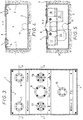
- the control device shown schematically in FIGS. 1 and 2 for a lifting platform contains a housing 1 with a base plate 2 and two longitudinal and transverse walls 3 and 4 existing Lower part and a cover plate 5, which has lateral fastening webs 6 screwed onto the rectangular lower part in plan view is.
- the cover plate 5 and the fastening webs 6 are designed such that it is possible to drive over the cover plate 5.
- Fig. 2 In the from e.g. Aluminum sheet existing cover plate 5 are in Fig. 2 shown pressure switches 7, 8, 9 and 10 as controls assembled. The connections of the controls for the electrical Lines are housed inside the lower part. At each one of the longitudinal and transverse walls 3 and 4 is one in the lower part opening empty pipe socket 11 and 12 for the lines to one Lift control and provided to the lift. In the base plate 2 is also a drain pipe 13 is arranged for Drainage of water or the like with an appropriate Drain pipe, a drain line or the like is connectable.
- a safety switch 10 is arranged to raise or lower the lift together with the corresponding pressure switch 7 or 9 must be operated.
- the distance between the Pressure switches 7 and 9 for raising and lowering and the safety switch 10 is chosen such that it does not match Foot can be operated.
- the lift must have the pressure switch 7 or 9 and the safety switch 10 can be operated together with one foot each. Thereby unintentional actuation of the lift is prevented.
- the emergency stop switch 10 can also be arranged in the central area be, as shown in Fig. 3, 5.
- another foot switch 17 for switching on a control voltage be provided. This foot switch 17 is after an emergency stop pressed to restore operational readiness.
- This foot switch is used to prevent accidental switching on 17 arranged slightly recessed.
- Control lamp 18 is required if the lift is also with a pneumatically operated lifting floor.
- the axle lift must be in a defined position when lowering or alignment, otherwise damage from Collision could occur, among other things, with the lifting floor. If the axle lift when lowering is not in this specified correct one Position, the lift only moves up to an uncritical one Point, which is indicated by this control lamp 18.
- Beeper 19 may be provided when lowering the lift sounds when it passes through a predetermined area.
- a cable clamp distributor in the housing 20 provided.
- the housing 1 is embedded in a floor, which here consists of a lower concrete layer 14 and an upper cover layer 15, e.g. one Finished floor, floor slabs or the like.
- the lower part is embedded in the floor in such a way that its upper edge and the surface of the cover plate 5 with the top edge of the floor 16 completes.
Landscapes
- Life Sciences & Earth Sciences (AREA)
- Engineering & Computer Science (AREA)
- Geology (AREA)
- Mechanical Engineering (AREA)
- Structural Engineering (AREA)
- Vehicle Step Arrangements And Article Storage (AREA)
- Refuge Islands, Traffic Blockers, Or Guard Fence (AREA)
- Forklifts And Lifting Vehicles (AREA)
- Push-Button Switches (AREA)
Abstract
Description
- Fig. 1
- eine Bedieneinrichtung im schematischen Längsschnitt;
- Fig. 2
- eine schematische Draufsicht der Bedieneinrichtung von Fig. 1;
- Fig. 3
- eine praktische Ausführung der Bedieneinxrichtung in detaillierter Draufsicht; und
- Fig. 4, 5
- die Bedieneinrichtung in den Querschnitten A-A und B-B in Fig. 3.
Claims (8)
- Bedieneinrichtung für eine Hebebühne, insbesondere für eine Kraftfahrzeughebebühne, die ein Gehäuse (1) mit mehreren Bedienelementen (7, 8, 9, 10) zur Betätigung der Hebebühne enthält,
dadurch gekennzeichnet, daß das im Fußboden (14, 15) versenkt angeordnete Gehäuse (1) eine im Fußbodenniveau (16) liegende Abdeckung (5) enthält, in der die als Fußschalter ausgebildeten Bedienelemente (7, 8, 9, 10) angeordnet sind. - Bedieneinrichtung nach Anspruch 1, dadurch gekennzeichnet, daß die Oberseite der Abdeckung (5) mit dem Fußbodenniveau (16) fluchtet.
- Bedieneinrichtung nach Anspruch 1 oder 2, dadurch gekennzeichnet, daß in der Abdeckung (5) je ein Fußschalter (7, 9) zum Anheben und zum Absenken der Hebebühne sowie in einem bestimmten Abstand ein zusätzlicher Sicherheits-Fußschalter (10) zum Aktivieren des jeweiligen Fußschalters (7 bzw. 9) angeordnet ist.
- Bedieneinrichtung nach einem der Ansprüche 1 bis 3, dadurch gekennzeichnet, daß in der Abdeckung (5) ein Fußschalter (8) zur Not-Abschaltung angeordnet ist.
- Bedieneinrichtung nach einem der Ansprüche 1 bis 4, dadurch gekennzeichnet, daß das Gehäuse (2, 3, 4) eine Fundamentwanne mit Bodenplatte (2) und Längs- und Querwänden (3, 4) ist.
- Bedieneinrichtung nach Anspruch 5, dadurch gekennzeichnet, daß in der Bodenplatte (2) ein Ablaufstutzen (13) angeordnet ist.
- Bedieneinrichtung nach Anspruch 5 oder 6, dadurch gekennzeichnet, daß in mindestens einer der Gehäusewand (3, 4) ein Leerrohrstutzen (11, 12) für die Leitungen zu einer Schalteinrichtung und der Hebebühne angeordnet ist.
- Bedieneinrichtung nach einem der vorhergehenden Ansprüche,
dadurch gekennzeichnet, daß im Gehäuse (1) oder in der Abdeckplatte (5) Anzeigen (18, 19) für bestimmte Betriebszustände vorgesehen sind.
Applications Claiming Priority (2)
| Application Number | Priority Date | Filing Date | Title |
|---|---|---|---|
| DE20008313U DE20008313U1 (de) | 2000-05-09 | 2000-05-09 | Bedieneinrichtung für eine Hebebühne |
| DE20008313U | 2000-05-09 |
Publications (2)
| Publication Number | Publication Date |
|---|---|
| EP1153878A2 true EP1153878A2 (de) | 2001-11-14 |
| EP1153878A3 EP1153878A3 (de) | 2004-01-21 |
Family
ID=7941244
Family Applications (1)
| Application Number | Title | Priority Date | Filing Date |
|---|---|---|---|
| EP01110129A Withdrawn EP1153878A3 (de) | 2000-05-09 | 2001-05-03 | Bedieneinrichtung für eine Hebebühne |
Country Status (4)
| Country | Link |
|---|---|
| US (1) | US6840351B2 (de) |
| EP (1) | EP1153878A3 (de) |
| CA (1) | CA2346568A1 (de) |
| DE (1) | DE20008313U1 (de) |
Families Citing this family (4)
| Publication number | Priority date | Publication date | Assignee | Title |
|---|---|---|---|---|
| CA2714779C (en) * | 2008-03-20 | 2014-10-21 | Rotary Lift, A Division Of Dover Industrial Products, Inc. | Lift control interface |
| US20110020215A1 (en) * | 2009-07-23 | 2011-01-27 | Ryu Wonhyoung | Chemical hydride formulation and system design for controlled generation of hydrogen |
| NL2011132C2 (en) | 2013-07-10 | 2015-01-13 | Stertil Bv | Lifting system for lifting a vehicle and method for operating the lifting system. |
| JP6559098B2 (ja) * | 2016-07-08 | 2019-08-14 | 株式会社バンザイ | 車両整備用リフト装置の電源監視装置 |
Family Cites Families (13)
| Publication number | Priority date | Publication date | Assignee | Title |
|---|---|---|---|---|
| US2681077A (en) * | 1948-09-29 | 1954-06-15 | Joyce Cridland Co | Actuating apparatus for plural valves controlling vehicle lifts |
| US3223124A (en) * | 1962-06-08 | 1965-12-14 | Joyce Cridland Co | Lift installation |
| US3936333A (en) * | 1971-10-26 | 1976-02-03 | Masonry Systems International, Inc. | Method for prefabricating brick panels |
| DE3152422A1 (de) * | 1981-04-16 | 1983-03-24 | Emil Dautel GmbH, 7105 Leingarten | Fussschalteinheit fuer eine hubladebuehne |
| DE3235829A1 (de) | 1982-09-28 | 1984-03-29 | Kirner Auto-Präzision Robert Fuchs GmbH & Co KG, 6570 Kirn | Hebebuehne fuer fahrzeuge, insbesondere personenkraftwagen |
| DE3916048A1 (de) | 1989-05-17 | 1990-11-22 | Soerensen Hydraulik Gmbh | Hebebuehne |
| US5340953A (en) * | 1992-11-19 | 1994-08-23 | A-Dec, Inc. | Switch controller |
| DE4430568B4 (de) | 1994-08-30 | 2010-01-07 | Dautel Gmbh | Hubladebühne für ein Lastfahrzeug |
| US5993146A (en) * | 1996-07-03 | 1999-11-30 | Blakesle Arpia Chapman | Apparatus for facilitating unloading and loading of articles on pallets |
| DE19724235A1 (de) | 1997-06-09 | 1998-12-10 | Lsd Umwelt Und Recyclingtechno | Vorrichtung zur Demontage von Gegenständen |
| DE19823535A1 (de) * | 1998-05-26 | 1999-12-02 | Gerd Baer | Fußsteuerung für eine Hubladebühne |
| US6325176B1 (en) * | 2000-02-10 | 2001-12-04 | Sörensen Hydraulik Zweigniederlossung Ulfborg Filial af Sörensen Hydraulik GmbH Tyskland | Control unit of loading platform system |
| EP1129897A1 (de) * | 2000-03-03 | 2001-09-05 | Gerd Bär GmbH | Zweifusssteuerung für eine Hubladebühne |
-
2000
- 2000-05-09 DE DE20008313U patent/DE20008313U1/de not_active Expired - Lifetime
-
2001
- 2001-05-03 EP EP01110129A patent/EP1153878A3/de not_active Withdrawn
- 2001-05-08 US US09/851,015 patent/US6840351B2/en not_active Expired - Fee Related
- 2001-05-08 CA CA002346568A patent/CA2346568A1/en not_active Abandoned
Also Published As
| Publication number | Publication date |
|---|---|
| CA2346568A1 (en) | 2001-11-09 |
| US20020005319A1 (en) | 2002-01-17 |
| US6840351B2 (en) | 2005-01-11 |
| EP1153878A3 (de) | 2004-01-21 |
| DE20008313U1 (de) | 2000-11-16 |
Similar Documents
| Publication | Publication Date | Title |
|---|---|---|
| DE69319079T2 (de) | Radiales, mechanisiertes Parkgaragensystem | |
| DE1069361B (de) | ||
| DE102018107807A1 (de) | Parksystem | |
| EP1153878A2 (de) | Bedieneinrichtung für eine Hebebühne | |
| DE3714053C2 (de) | Aufzug für Personentransport | |
| DE2644022C2 (de) | Vorrichtung zum Abstellen von Fahrzeugen auf mindestens zwei übereinander angeordneten Plattformen | |
| EP0377866B1 (de) | Weiterfahrtsanzeigeeinrichtung bei einem Aufzugssystem | |
| DE2139743A1 (de) | Vorrichtung zum parken mehrerer fahrzeuge uebereinander | |
| DE4113508C2 (de) | Bordstein für Bushaltestellen | |
| EP0060550B1 (de) | Garagenanlage | |
| CH632799A5 (en) | Double-storey garage | |
| DE1531102C3 (de) | Schachtausrüstung für einen Aufzug | |
| DE2430424A1 (de) | Ortsbewegliches fertighaus, insbesondere zur unterbringung von der stromumwandlung dienenden geraeten | |
| DE2302145C3 (de) | Einrichtung für eine Mehrfachgarage | |
| DE2363112A1 (de) | Stahlbetontraeger, insbesondere fuer herstellung von flachdaechern und decken | |
| DE102005007475B3 (de) | Personenlift | |
| DE2753290C2 (de) | Doppelstockgaragenanlage aus jeweils zwei transportablen Stahlbetoneinzelgaragen | |
| DE1684725A1 (de) | Versenkbare mehrstoeckige Parkplatz-Garage | |
| DE9111615U1 (de) | Garage für Kraftfahrzeuge | |
| DE10361783A1 (de) | Stellplatzsysteme zwei übereinander angeordneten Plattformen | |
| DE202006007863U1 (de) | Fundament-Ausbildung für Hebebühnen | |
| CH622309A5 (en) | Garage for parking vehicles on at least two platforms arranged one above the other | |
| DE9316166U1 (de) | Garage | |
| DE29521145U1 (de) | Mehrfachparkanlage | |
| WO2022112211A1 (de) | Kabinenboden für eine aufzugskabine und verfahren zur montage einer aufzugskabine |
Legal Events
| Date | Code | Title | Description |
|---|---|---|---|
| PUAI | Public reference made under article 153(3) epc to a published international application that has entered the european phase |
Free format text: ORIGINAL CODE: 0009012 |
|
| AK | Designated contracting states |
Kind code of ref document: A2 Designated state(s): AT BE CH CY DE DK ES FI FR GB GR IE IT LI LU MC NL PT SE TR |
|
| AX | Request for extension of the european patent |
Free format text: AL;LT;LV;MK;RO;SI |
|
| PUAL | Search report despatched |
Free format text: ORIGINAL CODE: 0009013 |
|
| AK | Designated contracting states |
Kind code of ref document: A3 Designated state(s): AT BE CH CY DE DK ES FI FR GB GR IE IT LI LU MC NL PT SE TR |
|
| AX | Request for extension of the european patent |
Extension state: AL LT LV MK RO SI |
|
| 17P | Request for examination filed |
Effective date: 20040712 |
|
| AKX | Designation fees paid |
Designated state(s): AT BE CH CY DE DK ES FI FR GB GR IE IT LI LU MC NL PT SE TR |
|
| GRAP | Despatch of communication of intention to grant a patent |
Free format text: ORIGINAL CODE: EPIDOSNIGR1 |
|
| STAA | Information on the status of an ep patent application or granted ep patent |
Free format text: STATUS: THE APPLICATION IS DEEMED TO BE WITHDRAWN |
|
| 18D | Application deemed to be withdrawn |
Effective date: 20080920 |