EP1154058A2 - Métier pour tissu éponge - Google Patents
Métier pour tissu éponge Download PDFInfo
- Publication number
- EP1154058A2 EP1154058A2 EP01109813A EP01109813A EP1154058A2 EP 1154058 A2 EP1154058 A2 EP 1154058A2 EP 01109813 A EP01109813 A EP 01109813A EP 01109813 A EP01109813 A EP 01109813A EP 1154058 A2 EP1154058 A2 EP 1154058A2
- Authority
- EP
- European Patent Office
- Prior art keywords
- warp thread
- warp
- pile
- thread
- sheet
- Prior art date
- Legal status (The legal status is an assumption and is not a legal conclusion. Google has not performed a legal analysis and makes no representation as to the accuracy of the status listed.)
- Withdrawn
Links
Images




Classifications
-
- D—TEXTILES; PAPER
- D03—WEAVING
- D03D—WOVEN FABRICS; METHODS OF WEAVING; LOOMS
- D03D39/00—Pile-fabric looms
- D03D39/22—Terry looms
- D03D39/223—Cloth control
Definitions
- the invention relates to a terry weaving machine with a first device for Delivery of a basic warp thread sheet and a second device for delivery at least a pile of warp threads, with fabric threading agents and with compartment-forming elements for the Warp threads.
- the compartment-forming elements are weft insertion means and weft attachment means assigned to the weft threads at a predetermined distance of the web line or the edge of the goods (partial stop) and then the entered Weft threads in groups on the stop edge, i.e. the edge of the goods (full or group posting).
- group stop the pile warp thread tension lowered and the warp thread yielded so that the warp threads are too Loops are set up while the weft threads are held between the tensioned Basic warp threads slide until they are attached to the goods edge.
- the terry weave which is only outlined in its basic features, is a well-known one Weaving technology, which is described, for example, in the book "WEBEREI Maschinen für die Tissue production "by Dipl.-Ing. J. Schneider, Springer-Verlag Berlin / Göttingen / Heidelberg 1961, pages 17, 277.
- a typical example of a terry weaving machine is from DE-PS 2225604 known, in which the basic structure of such a terry weaving machine is illustrated.
- the basic warp threads are released from a basic thread warp beam and redirected to the horizontal weaving plane via a spring-loaded spanning tree they are united with the pile of warp threads by one above the weaving plane arranged pile thread warp beam is lowered.
- the pile warp threads are around their own spring-loaded tensioning boom, which is arranged above the base warp thread coulter, extends across the width of the weave and the pile warp threads from above, essentially tangential, introduces into the basic warp thread family.
- the basic warp threads and the pile warp threads pass through warp thread monitors arranged in the weaving plane, behind which they work together Pass through shedding elements in the form of healds to pass through them Advised or reed to extend to the fabric edge, the so-called Stop edge forms.
- the shed produced by the healds lies with the The tip of his front compartment at the stop edge and ends with the tip of his Rear compartment in the area of support rods for the basic and pile warp yarn coulters common warp stop motion.
- the pile of warp threads runs over one Spring-loaded, arranged above the weaving plane and the basic warp thread family Dancer shaft at a small acute angle from above into the basic warp thread family a, the pile warp threads only in the area of the rear compartment between the base warp threads penetration.
- the warp thread monitors can therefore only be arranged as described above become.
- the terry weaving compared to the Smooth weaving is more difficult and complex.
- the well-known terry weaving machines therefore only the function in the foreground, which ensures that the Loop formation, the warp tension control for basic and pile warp threads as well as the Warp thread monitoring for the production of terry fabrics are perfectly possible.
- these machines which are often quite complicated, little is paid to Accessibility, for example the warp thread monitor and ease of use. Because of The increasing increase in the performance of weaving machines is becoming more and more Warp beams with a larger capacity are used, which increases the accessibility of the Warp thread monitor for its operation is further deteriorated.
- the invention is therefore based on the object of a terry weaving machine create that with high performance and operational safety through better Easy to use and maintain.
- the basic warp thread family and the pile warp thread family are separate from each other separate warp thread monitors assigned, which from at least one machine side, i.e. are freely accessible on the warp beam side or fabric side.
- the Warp thread monitors for the basic warp thread coulter and the warp thread monitors for the The pile of warp threads can be arranged on two different levels, which means that Accessibility is usually further improved.
- at least the The pile warp thread in the area of the pile warp guard in a preferably horizontal one Level. Precisely due to the arrangement of the pile and basic warp thread monitors in The warp thread break repair is very different on two different levels easy to use. Because of the between the pile warp threads and the base warp threads formed crosshairs can namely a warp thread break in the rear compartment easy to control and easy to fix by the operating personnel.
- the pile warp thread family is the basic warp thread family crossing through in an area that passes between that of the compartment-forming elements formed back pocket of the pile warp threads and the delivery device the basic warp thread family lies.
- the terry loom expediently has deflection means for the Pile warp threads on that of the delivery device for the pile warp yarn sheet opposite side of the base warp yarn sheet are arranged.
- This deflecting means may at least have a deflecting rod over which the pile of warp threads is guided.
- the deflecting rod can be designed as an articulated rod, which extends several times over the weaving width is stored and supported.
- the deflection rod can be used to keep the frictional forces low be rotatably supported, as may also be expedient, the deflecting rod resilient to be resiliently stored and, if necessary, adjustable.
- the arrangement can be made such that the pile warp and the Basic warp thread coulter at the crossing point, seen in the thread running direction, a blunt or enclose an acute angle with each other, the two warp thread groups can also cross at an angle of about 90 °.
- the pile warp threads achieved a strong reciprocation of the pile warp threads in the area of the warp thread monitor is avoided.
- the pile of warp threads is conveniently in an area in the thread running direction before the intersection with the base warp thread family lies, passed through a device for forming a pile warp reserve, the a compensation of the length of the warp threads when forming loops and / or changing the subject causes.
- This device for forming a pile warp thread reserve can be at least one spring-loaded, partially wrapped by the pile warp threads, Have thread length compensation element that, for example, a resiliently mounted Deflection rod is or a resiliently designed and / or stored thread deflection plate having.
- the described guiding of the warp threads allows the resulting pile warp thread length for loop formation in terry weaving with fabric control or terry weaving with store control in such a way that the pile warp tension before Group stop is lowered and the spring-loaded deflection rod or that Spring plate-like deflection plate partially absorb the pile warp thread length.
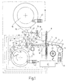
- FIGS. 1 to 8 are only the essential elements in FIGS. 1 to 8 shown.
- Each of these terry weaving machines has a first device for delivering one Basic warp thread sheet 1 with a basic thread warp beam 2, from which the Basic warp thread family 1 about a fixed axis 3 against the action of Spring means 4 pivotally mounted tension roller and a match tree 6 is guided the warp thread sheet 1 in the essentially horizontal working or weaving plane above of the basic thread warp beam 2.
- Between the match tree 6 and one at 7 Breast structure shown are compartment-forming elements in the form of shafts 8 with Healds 9 arranged, known by a mechanism not shown Kind to be moved up and down for specialist training.
- the shafts 8 are not shown Assigned weft insertion means which, depending on the design of the terry loom In the form of compressed air nozzles, of grippers, as a boat, etc. can.
- the weft threads entered in the shed shown at 10 are from Weft thread sling means in the form of a reed or reed 11 each in groups in the usual manner in terry weaving to the stop edge 12 of the one shown at 13 Chipped fabric.
- the tissue 13 is then after the breast tree 7 over a designed as a spiked roller feed roller 14, from which it in a known manner a goods tree, not shown, arrives on which it is wound up.
- the Riet 11 which is rigidly attached to a sley 15 (Fig. 8), leads a back and forth Movement between a rear position seen in the direction of the thread and a front stop position. In those shown in Figures 1 to 6 Terrycloth looms are the stroke of this reciprocating movement of reed 11 constant.
- a second device for supplying a pile warp thread sheet 15 with a pile thread warp beam 16 arranged, from which the pile warp yarn sheet 15 is lowered controlled.
- the pile warp thread sheet 15 is taken from the pile thread warp beam 16 coming first through a rotatably mounted deflection roller 17 into a Substantially horizontal redirected level, in which the tuft threads a pile warp stop 18 pass through, the warp thread guard slats spreading on the pile warp threads with 19 are designated.
- the pile warp guard 18 is of a known type and, for example in the book "WEBEREI” processes and machines for fabric production, Springer-Verlag 1961 ok P.421 ff.
- the guard slats 19 are on both sides
- the pile warp yarn sheet 15 is supported on bars 20, 21 which are continuous over the weaving width, from to which the rod 21 adjacent to the shafts 8 has the pile warp thread 15 guided over it deflected about 90 °. A deflection of more or less than 90 ° is conceivable.
- a deflecting element extending over the weaving width in the form of a over the weaving width mounted and supported, rotatably mounted deflection rod 22 which the of the pile 21 coming pile warp thread 15 in the working or weaving plane and in Rear compartment 23 of the shed 10 deflects.
- the deflecting bar 22 is positioned in such a way that it supports the base warp thread sheet 1, so that the compartment tip of the rear compartment 23 for both the basic warp threads and for the The pile warp threads are located at the deflecting rod 22.
- the deflection rod 22 is, as mentioned, rotatable stored, but it can also be held non-rotatably and / or by several, 15 deflecting rods and / or rollers wrapped by the pile of warp threads 15 may be replaced.
- the deflection rod 22 is on levers 24 about a horizontal axis 25 against the Effect of spring means, not shown, pivotally mounted, which are striving to keep the pile of warp threads 15 taut.
- the spring-loaded deflecting rod 22 causes a pile warp length compensation for those who change the weaving process and changes occurring in the formation of pole loops of the processed Pile warp thread lengths.
- the thread path between the rod 21 of the Polkettfadenissechters 18 and the deflecting rod 22 a spring-loaded dancer shaft 26th be arranged, which is partially wrapped by the pile warp threads and also to do so serves to accommodate a warp thread length compensation for the pile warp thread lengths, which, as mentioned, during the weaving process of looping and changing the subject occurs.
- the dancer shaft 26 can also be rotated by a stationary shaft or a Deflection rod to be replaced.
- the rod 21 in the Thread path of the pile of warp yarns 15 downstream, continuous over the weaving width, spring plate-like thread deflecting plate 28 occur, as is illustrated in FIG. 5. This acting as a spring element thread deflecting plate 28 acts just like the spring-loaded Dancer shaft 26 according to FIG. 1 in the sense of calming the warp thread guard slats 19.
- the 1 arranged deflecting rod 22 can also be adjusted about the axis 25 by means of its bearing lever 24 can be stored such that the deflection point of the pile warp sheet 15 and thus their Intersection with the base warp thread sheet 1 in the direction of the shafts 8 to or from this way is adjustable.
- the pile warp yarn sheet 15 is such by the shaft 26 and the deflecting rod 22 led that they at the intersection with the basic warp thread sheet 1, in the thread running direction seen includes an obtuse angle 29 of about 130 °.
- the shaft 26 and / or the deflecting rod 22 By adjusting the shaft 26 and / or the deflecting rod 22, the size of this angle 29 can be changed as required and adjusted accordingly.
- the basic warp thread sheet 1 is on the thread path between the match tree 6 and the deflecting rod 22, i.e. the compartment tip of the rear compartment 23, by a Warp thread monitor 30 is monitored for warp thread breakage, its warp thread monitor slats 33 spread on the warp threads which are guided essentially horizontally over two rods 31, 32.
- the warp thread monitor 30 is basically of the same design as the warp thread monitor 18 for the pile of warp threads 15.
- the warp thread monitor 30 is the Basic warp thread sheet 1 from the warp beam side (Fig. 1, left) easily accessible because it is too this machine side is exposed and is not covered by the pile warp sheet 15.
- the warp thread monitor 18 for the pile warp thread sheet 15 is, as shown in FIG. 1, on one from the warp thread monitor 30 separate, indicated at 34 by dash-dotted lines, horizontal Level arranged, the distance above the work or web level and thus in Distance to the basic warp thread sheet 1 passing through the warp thread monitor 30.
- the Warp thread monitor 18 for the pile of warp threads 15 is therefore from the fabric take-off side (in Fig. 1 right) of the machine from freely accessible, so that even warp thread breaks easily and can be fixed without hindrance.
- the concept described results in the arrangement of the warp thread monitors 18, 30 for the pile warp sheet 15 or the base warp sheet 1 on separate levels and the passage of the pile warp yarn sheet 15 crossing the base warp yarn sheet 1 the basic warp thread coulter 1 is a very user-friendly, ergonomically favorable, compact and simple construction of the whole terry loom.
- the match tree 6 is on both sides around a horizontal axis pivotally mounted rocker 36 which is rotatably supported by a Coupling linkage 37 with the fabric feed roller 14 and with a double arm Adjusting lever 38 for the tissue control is coupled.
- the spring-loaded adjusting lever 38 which is designed in the form of an angle lever, is shown by one in FIG Toweling eccentric 39 back and forth about a fixed axis 40 according to arrow 41 in FIG.
- the warp beam 2 of the basic warp thread family 1, the warp beam 16 of the pile warp thread family 15 and the fabric feed roller 14 are by their own, individually assigned drive motors 42, 43, 44 driven, the warp let-off of the base warp threads and the pile warp threads and the Control deduction of fabric 13.
- a machine control unit (CPU) 45 is provided for this purpose, that of a respective representative number of basic warp threads or pile warp threads monitoring warp thread tension sensor 46 or 47 coming electrical signals processed and also by a sensor 48 coupled to the deflection roller 17 Information about the used warp thread lengths and from one of the Machine main shaft driven, incremental encoder wheel 49 information provided about the motion sequences derived from the machine main shaft during the training and the movement of the reed 11.
- the basic warp thread family 1 is at this terry machine with a match / breast tree system Warp length compensation performed by springs 4 and with positive control.
- the Warp thread tension sensors 46, 47 are in front of the thread running direction Warp thread monitor 30 or 18 arranged, i.e. in an area with a quiet thread course.
- FIG. 9 The basic function of the fabric control in terry weaving with the Terry loom is illustrated in Fig. 9, where the top representation a) the Shows the eccentric stroke of the terry cam 39 (FIG. 6) as a function of its angle of rotation, while the lower illustration shows that controlled by the drive motor 43 Play warp thread.
- the stop edge 12 Starting from the rear position of the stop edge in the previous group weft stop took place, the stop edge 12 in transferred the front position in which the stop edge 12 is further away from the reed 11 stands. During this displacement of the stop edge 12, the required The pile warp thread length is lowered so that the pile warp thread tension is kept approximately constant becomes.
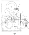
- a jacquard terry weaving machine is shown, in its basic structure of the terry loom according to Fig. 1 corresponds. The same parts are therefore designated by the same reference numerals and not explained further.
- the machine has a harness indicated at 50, the cords of which Healds 9 run and the warp thread monitors 18 for the pile warp threads 15 and 30 for the basic warp thread sheet 1 covers the fabric feed side.
- the warp thread monitor 18 for the Polkettfadenschar 15 is therefore compared to the conditions at 1 more towards the warp beam side, so that it from the Warp beam side is easily accessible for the operator.
- the deflection roller 17 is moved closer to the fabric feed roller 14 and almost directs the pile warp yarn sheet 15 360 ° around.
- the pile warp sheet 15 is again in Mainly performed in the horizontal plane 34. It is through the rod 21 by about 90 ° deflected and penetrates the basic warp thread sheet 11 in the working or weaving plane below an acute angle 29 ', the size of which can be close to 90 °.
- the pile warp thread guide in such a jacquard terry weaving machine also designed similar to the terry loom according to FIG. 1 be if the structural conditions of the machine appear to be expedient to let.
- FIG. 3 Such a variant of a jacquard terry weaving machine is shown in FIG. 3 illustrated.
- the pile warp threads cross the base warp threads on the Crossing point at the deflection bar 22 e.g. at the obtuse angle 29 of FIG. 1.
- the pile warp threads and the warp thread guard slats 19 remain in any case easily accessible from the warp beam side of the weaving machine, while the warp thread monitor 30 of the basic warp thread coulter 1 is conveniently operable on the warp beam side anyway.
- the terry loom shown in FIG. 4 is largely the same as that of FIG. 1 built up. The difference is that instead of the pivotally mounted on rocker 36 Match tree 6 of the machine according to FIG. 1, the match tree 6 'of the terry weaving machine Fig. 4 is rotatably mounted and at one point on its circumference an axially parallel, on the Weaving continuous, radially projecting cam 51 against which the Basic warp thread sheet 1 can support. In the opposite direction to the thread running direction Movement of the stop edge 12 to the group stop of the weft threads within the Tissue control is the match tree 6 ', starting from the position shown in FIG. 4, together with the fabric feed roller 14 through the terry eccentric 39 (Fig. 5) in Twisted counterclockwise.
- the terry weaving machine shown corresponds basically the terry loom according to Fig. 1, in particular the leadership of the The pile warp sheet 15 and the base warp sheet 1 are formed in the same way.
- the warp thread monitors 18 and 30 for the pile warp thread 15 and the Basic warp thread coulters 1 are arranged as in FIG. 1.
- the sley 57 shown in FIG. 8 can be pivoted about a horizontal axis 52 stored. It is coupled to the main shaft of the weaving machine at 53 schematically illustrated eccentric drive with constant stroke back and forth. On the sley 57 is the reed (reed) 11 about an axis parallel to the pivot axis 52 54 pivoted. An eccentric drive 55 assigned to the sley 57 can be the reed 11 pivot controlled with respect to the sley 57, as indicated by a double arrow 56 is indicated.
- the eccentric drive 53 controls the reciprocating movement of the sley 15 Partial stop of the weft threads at a distance from the stop edge 12.
- the reed is 11 rigidly connected to the sley 57. Swiveled to carry out the group attack the eccentric 55 the reed 11 to the extent necessary with respect to the sley 15, so that the registered weft thread group is struck on the stop edge 12.
- the Movements of the eccentric drives 53, 55 are derived from the main shaft of the machine.
Landscapes
- Engineering & Computer Science (AREA)
- Textile Engineering (AREA)
- Looms (AREA)
- Treatment Of Fiber Materials (AREA)
Applications Claiming Priority (2)
| Application Number | Priority Date | Filing Date | Title |
|---|---|---|---|
| DE10023445A DE10023445A1 (de) | 2000-05-12 | 2000-05-12 | Frottierwebmaschine |
| DE10023445 | 2000-05-12 |
Publications (2)
| Publication Number | Publication Date |
|---|---|
| EP1154058A2 true EP1154058A2 (fr) | 2001-11-14 |
| EP1154058A3 EP1154058A3 (fr) | 2005-06-08 |
Family
ID=7641896
Family Applications (1)
| Application Number | Title | Priority Date | Filing Date |
|---|---|---|---|
| EP01109813A Withdrawn EP1154058A3 (fr) | 2000-05-12 | 2001-04-21 | Métier pour tissu éponge |
Country Status (4)
| Country | Link |
|---|---|
| US (1) | US6367511B2 (fr) |
| EP (1) | EP1154058A3 (fr) |
| JP (1) | JP3416661B2 (fr) |
| DE (1) | DE10023445A1 (fr) |
Cited By (1)
| Publication number | Priority date | Publication date | Assignee | Title |
|---|---|---|---|---|
| EP1621654A3 (fr) * | 2004-07-28 | 2007-06-06 | Tsudakoma Kogyo Kabushiki Kaisha | Système d'entraînement des membres de formation de boucles dans un métier pour tissu éponge du type à toile mobile |
Families Citing this family (7)
| Publication number | Priority date | Publication date | Assignee | Title |
|---|---|---|---|---|
| DE10204945B4 (de) * | 2002-02-07 | 2006-06-14 | Lindauer Dornier Gmbh | Frottierwebverfahren zur Ausbildung variabler Schlingenhöhen und Frottierwebmaschine zur Verfahrensdurchführung |
| DE102005022955A1 (de) * | 2005-05-19 | 2006-11-23 | Lindauer Dornier Gmbh | Verfahren und Vorrichtung zum Halten eines nach einem Startvorgang einer Webmaschine, insbesondere Luftdüsenwebmaschine eingetragenen Schussfadens |
| CN101525801B (zh) * | 2009-04-08 | 2010-12-01 | 王勇 | 毛巾机的停送停卷机构 |
| DE102010026609B3 (de) * | 2010-07-09 | 2011-11-17 | Lindauer Dornier Gesellschaft Mit Beschränkter Haftung | Verfahren und Vorrichtung zur Webmusterbildung bei Geweben mit Zusatzschusseffekten |
| DE102010034969B3 (de) | 2010-08-20 | 2011-11-03 | Lindauer Dornier Gesellschaft Mit Beschränkter Haftung | Webblatt und Webmaschine zur Webmusterbildung bei Geweben mit Zusatzmustereffekten |
| WO2015111077A2 (fr) * | 2014-01-22 | 2015-07-30 | Ansari Afzal Ahmed Akhlaque Ahmed | Métier à tisser à lances |
| US9828704B2 (en) * | 2015-09-10 | 2017-11-28 | Welspun India Limited | Terry article with synthetic filament yarns and method of making same |
Family Cites Families (19)
| Publication number | Priority date | Publication date | Assignee | Title |
|---|---|---|---|---|
| FR892656A (fr) * | 1942-11-20 | 1944-05-16 | Diederichs Atel | Disposition d'ensouple pour métiers à tisser en particulier à fabriquer le tissu éponge |
| US2625959A (en) * | 1950-05-05 | 1953-01-20 | Crompton & Knowles Loom Works | Needle loom |
| US2625956A (en) * | 1950-09-25 | 1953-01-20 | Edinburgh Corp | Loop warp tension-variable beat-up apparatus for terry looms |
| FR1258281A (fr) * | 1960-02-29 | 1961-04-14 | Diederichs Atel | Perfectionnements aux casse-chaîne des métiers à tisser les tissus à boucles par la chaîne et en particulier les tissus éponge |
| GB1072831A (en) * | 1965-01-19 | 1967-06-21 | West Point Pepperell Inc | Terry pile fabric and method of manufacturing such fabric |
| US3434504A (en) * | 1967-10-17 | 1969-03-25 | Cannon Mills Co | Shuttleless terry loom warp shedding means and method |
| CH550872A (de) * | 1972-04-24 | 1974-06-28 | Sulzer Ag | Webmaschine zur herstellung von frottiergewebe. |
| CH552693A (de) * | 1972-05-23 | 1974-08-15 | Sulzer Ag | Webmaschine zur herstellung von frottiergewebe. |
| EP0139805B1 (fr) * | 1983-11-01 | 1988-03-09 | GebràDer Sulzer Aktiengesellschaft | Machine à tisser les tissus éponge |
| US4721134A (en) * | 1986-08-04 | 1988-01-26 | West Point Pepperell, Inc. | Terry loop ratio control device |
| JPS6410088U (fr) * | 1987-07-08 | 1989-01-19 | ||
| EP0350446B1 (fr) * | 1988-07-08 | 1992-04-01 | GebràDer Sulzer Aktiengesellschaft | Procédé de fabrication de tissu éponge et métier à tisser avec des organes de formation du poil |
| IT1227302B (it) * | 1988-10-07 | 1991-04-05 | Nuovo Pignone Spa | Dispositivo perfezionato di tensionatura dei fili di ordito in un telaio tessile |
| DE4005751A1 (de) * | 1990-02-23 | 1991-08-29 | Dornier Gmbh Lindauer | Seersucker-einrichtung |
| JPH07126952A (ja) * | 1993-11-05 | 1995-05-16 | Toyota Autom Loom Works Ltd | パイル織機におけるパイル用経糸切断検出方法 |
| DE19530222C1 (de) * | 1995-08-17 | 1996-06-05 | Dornier Gmbh Lindauer | Steuersystem für die Polkette zur Herstellung von Frottiergewebe auf Webmaschinen |
| DE19626417B4 (de) * | 1995-09-07 | 2006-07-06 | SULZER RüTI AG | Frottierwebmaschine mit Florkettspannungskompensation |
| DE19537277C1 (de) | 1995-10-06 | 1996-08-08 | Dornier Gmbh Lindauer | Frottierwebmaschine mit einer Florhöhenverstelleinrichtung |
| DE19836453C1 (de) | 1998-08-12 | 1999-11-25 | Dornier Gmbh Lindauer | Verfahren zum Bilden erster und zweiter Florhöhen beim Weben von Frottiergewebe und Webmaschine zur Durchführung des Verfahrens |
-
2000
- 2000-05-12 DE DE10023445A patent/DE10023445A1/de not_active Ceased
-
2001
- 2001-04-21 EP EP01109813A patent/EP1154058A3/fr not_active Withdrawn
- 2001-05-14 US US09/855,150 patent/US6367511B2/en not_active Expired - Fee Related
- 2001-05-14 JP JP2001143707A patent/JP3416661B2/ja not_active Expired - Fee Related
Cited By (1)
| Publication number | Priority date | Publication date | Assignee | Title |
|---|---|---|---|---|
| EP1621654A3 (fr) * | 2004-07-28 | 2007-06-06 | Tsudakoma Kogyo Kabushiki Kaisha | Système d'entraînement des membres de formation de boucles dans un métier pour tissu éponge du type à toile mobile |
Also Published As
| Publication number | Publication date |
|---|---|
| US20010039974A1 (en) | 2001-11-15 |
| JP3416661B2 (ja) | 2003-06-16 |
| US6367511B2 (en) | 2002-04-09 |
| JP2001355148A (ja) | 2001-12-26 |
| DE10023445A1 (de) | 2001-11-29 |
| EP1154058A3 (fr) | 2005-06-08 |
Similar Documents
| Publication | Publication Date | Title |
|---|---|---|
| EP2531639B1 (fr) | Métier à tisser pour la production de tissus à effets trame supplémentaires | |
| DE69713348T2 (de) | Kettfadenkontrollvorrichtung zur herstellung von drehgewebe auf webmaschinen | |
| EP1395692B1 (fr) | Metier a tisser destine a la production d'un tissu en gaze | |
| EP0626475B1 (fr) | Procédé et dispositif pour influencer la tension dans une chaîne de poil lors de la fabrication de tissus éponge sur des métiers à tisser | |
| EP1120485B1 (fr) | Métier à tisser un tissu en gaze | |
| EP1154057A2 (fr) | Métier pour tissu éponge | |
| EP1122345A1 (fr) | Procédé pour la fabrication d'un tissu de base à armure de gaze et métier à tisser pour la mise en oeuvre dudit procédé | |
| EP2741988B1 (fr) | Procédé et métier à tisser muni d'un dispositif de surveillance d'une surtension des fils | |
| EP1154058A2 (fr) | Métier pour tissu éponge | |
| EP1299586B1 (fr) | Dispositif pour former un tissu de gaze | |
| DE102004063683A1 (de) | Verfahren zum Herstellen eines Gewebes in Dreherbindung und Webmaschine zur Durchführung des Verfahrens | |
| DE2444411C3 (de) | Bandwebmaschine mit mehreren mit Litzen versehenen Schäften | |
| DE69909907T2 (de) | Vorrichtung zur Überwachung der Fadenreserve in Schussfadenliefervorrichtungen für Webmaschinen | |
| EP1255885B1 (fr) | Procede pour devier une portee de fils de chaine pendant le tissage, et metier a tisser | |
| EP0761857B1 (fr) | Système de contrôle de la chaíne de poil lors de la fabrication de tissu éponge sur métier à tisser | |
| DE2724923C3 (de) | Zwillings-Düsen-Webmaschine | |
| DE10023444A1 (de) | Frottierwebmaschine | |
| DE102012009420A1 (de) | Vorrichtung zum Herstellen eines Gewebes | |
| DE102005028127A1 (de) | Frottierwebmaschine | |
| DE2221282C3 (de) | Webmaschine zur Herstellung von Frottiergewebe | |
| DE1255599B (de) | Webmaschine mit einem Streichbaum fuer die Kette und einem den Streichbaum tragenden Tragbaum sowie mit einer Vorrichtung zum periodischen Strecken und Nachlassen von Kettenfaeden | |
| DE10159236C1 (de) | Verfahren zur Kompensation der Zugspannung in einer Webkette bei Fachwechsel und Webmaschine zur Durchführung des Verfahrens | |
| EP3529404B1 (fr) | Dispositif de mesure de la tension de chaîne dans une machine à tisser et machine à tisser équipée d'un tel dispositif | |
| DE3043147C2 (de) | Webmaschine mit Schneidvorrichtung | |
| DE1979594U (de) | Kettbaumaufhaengung an webmaschine. |
Legal Events
| Date | Code | Title | Description |
|---|---|---|---|
| PUAI | Public reference made under article 153(3) epc to a published international application that has entered the european phase |
Free format text: ORIGINAL CODE: 0009012 |
|
| AK | Designated contracting states |
Kind code of ref document: A2 Designated state(s): AT BE CH CY DE DK ES FI FR GB GR IE IT LI LU MC NL PT SE TR |
|
| AX | Request for extension of the european patent |
Free format text: AL;LT;LV;MK;RO;SI |
|
| PUAL | Search report despatched |
Free format text: ORIGINAL CODE: 0009013 |
|
| AK | Designated contracting states |
Kind code of ref document: A3 Designated state(s): AT BE CH CY DE DK ES FI FR GB GR IE IT LI LU MC NL PT SE TR |
|
| AX | Request for extension of the european patent |
Extension state: AL LT LV MK RO SI |
|
| AKX | Designation fees paid | ||
| STAA | Information on the status of an ep patent application or granted ep patent |
Free format text: STATUS: THE APPLICATION IS DEEMED TO BE WITHDRAWN |
|
| 18D | Application deemed to be withdrawn |
Effective date: 20051101 |
|
| REG | Reference to a national code |
Ref country code: DE Ref legal event code: 8566 |