EP1154338A2 - Système de nettoyage et méthode de formation d'images - Google Patents
Système de nettoyage et méthode de formation d'images Download PDFInfo
- Publication number
- EP1154338A2 EP1154338A2 EP01304001A EP01304001A EP1154338A2 EP 1154338 A2 EP1154338 A2 EP 1154338A2 EP 01304001 A EP01304001 A EP 01304001A EP 01304001 A EP01304001 A EP 01304001A EP 1154338 A2 EP1154338 A2 EP 1154338A2
- Authority
- EP
- European Patent Office
- Prior art keywords
- toner
- cleaning
- image
- bearing member
- voltage
- Prior art date
- Legal status (The legal status is an assumption and is not a legal conclusion. Google has not performed a legal analysis and makes no representation as to the accuracy of the status listed.)
- Granted
Links
Images






Classifications
-
- G—PHYSICS
- G03—PHOTOGRAPHY; CINEMATOGRAPHY; ANALOGOUS TECHNIQUES USING WAVES OTHER THAN OPTICAL WAVES; ELECTROGRAPHY; HOLOGRAPHY
- G03G—ELECTROGRAPHY; ELECTROPHOTOGRAPHY; MAGNETOGRAPHY
- G03G21/00—Arrangements not provided for by groups G03G13/00 - G03G19/00, e.g. cleaning, elimination of residual charge
- G03G21/0005—Arrangements not provided for by groups G03G13/00 - G03G19/00, e.g. cleaning, elimination of residual charge for removing solid developer or debris from the electrographic recording medium
-
- G—PHYSICS
- G03—PHOTOGRAPHY; CINEMATOGRAPHY; ANALOGOUS TECHNIQUES USING WAVES OTHER THAN OPTICAL WAVES; ELECTROGRAPHY; HOLOGRAPHY
- G03G—ELECTROGRAPHY; ELECTROPHOTOGRAPHY; MAGNETOGRAPHY
- G03G21/00—Arrangements not provided for by groups G03G13/00 - G03G19/00, e.g. cleaning, elimination of residual charge
- G03G21/0005—Arrangements not provided for by groups G03G13/00 - G03G19/00, e.g. cleaning, elimination of residual charge for removing solid developer or debris from the electrographic recording medium
- G03G21/007—Arrangement or disposition of parts of the cleaning unit
- G03G21/0076—Plural or sequential cleaning devices
-
- G—PHYSICS
- G03—PHOTOGRAPHY; CINEMATOGRAPHY; ANALOGOUS TECHNIQUES USING WAVES OTHER THAN OPTICAL WAVES; ELECTROGRAPHY; HOLOGRAPHY
- G03G—ELECTROGRAPHY; ELECTROPHOTOGRAPHY; MAGNETOGRAPHY
- G03G2221/00—Processes not provided for by group G03G2215/00, e.g. cleaning or residual charge elimination
- G03G2221/0005—Cleaning of residual toner
-
- G—PHYSICS
- G03—PHOTOGRAPHY; CINEMATOGRAPHY; ANALOGOUS TECHNIQUES USING WAVES OTHER THAN OPTICAL WAVES; ELECTROGRAPHY; HOLOGRAPHY
- G03G—ELECTROGRAPHY; ELECTROPHOTOGRAPHY; MAGNETOGRAPHY
- G03G2221/00—Processes not provided for by group G03G2215/00, e.g. cleaning or residual charge elimination
- G03G2221/0005—Cleaning of residual toner
- G03G2221/001—Plural sequential cleaning devices
-
- G—PHYSICS
- G03—PHOTOGRAPHY; CINEMATOGRAPHY; ANALOGOUS TECHNIQUES USING WAVES OTHER THAN OPTICAL WAVES; ELECTROGRAPHY; HOLOGRAPHY
- G03G—ELECTROGRAPHY; ELECTROPHOTOGRAPHY; MAGNETOGRAPHY
- G03G2221/00—Processes not provided for by group G03G2215/00, e.g. cleaning or residual charge elimination
- G03G2221/0005—Cleaning of residual toner
- G03G2221/0015—Width of cleaning device related to other parts of the apparatus, e.g. transfer belt width
Definitions
- the present invention relates to a cleaning system to clean an image bearing member used in electrophotographic process and an image forming system equipped with said cleaning system.
- an image bearing member cleaning means is used to clean the surface of the image bearing member with a great deal of toner remaining thereon without being transferred, for example, after sudden suspension of the operation due to paper jamming or the like or on the patch created for image adjustment or the like.
- electrostatic latent image is formed on the image bearing member. After that, said electrostatic latent image is developed by toner to create a toner image. After said toner image is transferred, paper powder adhering to said carrier surface or remaining toner having failed to be transferred is removed by the cleaning system.
- Amorphous toner produced according to the conventional pulverization method (average circularity of 0.95 or less) has been sufficiently scraped off only when the end of an elastic plate member called a cleaning blade is brought into mechanical contact with the surface of the image bearing member to scrape it off.
- the object of the present invention is to solve the problems in conventional cleaning technologies as indicated above.
- the object of the present invention can be attained by cleanig apparatus described as follow.
- Fig. 1 is a drawing representing an image forming system as an embodiment according to the present invention.
- numeral 1 denotes a photoconductor as an image bearing member.
- said photoconductor is preferred to be an organic photoconductor with photosensitive layer consisting of resin with organic photoconductor dispersed thereon.
- Numeral 2 denotes a charging device to charge said photoconductor 1 and to build up uniform potential on the photoconductor 1.
- This charging device is preferred to be a Scorotron charging device having a control grid and discharge electrode, or a charging device based on contact charging, using a roller with voltage applied thereto.
- Numeral 3 indicates a exposure device for exposing the photoconductor 1 according to the image data.
- the exposure device is preferred to a scanning exposure device with a scanning optical system consisting of a polygon mirror, lens and mirror where a laser diode is used as a light source.
- Another preferred exposure device is a scanning optical device with light emitting diode array and imaging optical fiber. Said exposure device 3 provides dot exposure of the photosensor 1 according to the image data.
- Numeral 4 indicates a development device. It stores one-component developer or two-component developer, and carries the developer to the area of developer by means of a development sleeve 41. It develop the electrostatic latent image on the photoconductor 1 to form a toner image on the photoconductor 1.
- the development sleeve is supplied with the d.c. development bias having the same polarity as the charging polarity of charging device 2 or development bias having the same polarity as the charging polarity of charging device 2 superimposed on the a.c. voltage. This is followed by the step of reversal development where toner is attached to the portion exposed by the exposure device 3.
- Numeral 5 denotes a transfer device comprising a corona charging device.
- the transfer device 5 charges the recording paper P in the polarity reverse to that of toner on the photoconductor 1, and transfers the toner image to the recording paper P.
- Numeral 6 denotes a separator comprising a corona charging device. It provides a.c. corona charging to recording paper P to eliminate electric charge from the recording paper P, and separate the paper from the photoconductor 1.
- Numeral 7 denotes a fixing device. It fixes toner image on the recording paper P by means of a heating roller 71 with a built-in heating source (e.g. halogen lamp) and a heating roller 72 in contact therewith.
- a heating roller 71 with a built-in heating source (e.g. halogen lamp) and a heating roller 72 in contact therewith.
- Numeral 8 indicates a cleaning system. Toner yet to be transferred or toner remaining after transfer is deposited on the photoconductor 1 after transfer. To start the next image formation step, the photoconductor 1 must be cleaned.
- Cleaning system 8 has a cleaning blade 81 consisting of elastic blade such as urethane rubber and a cleaning roller 82.
- the cleaning blade 81 is supported by a fixed blade holder 83, and the tip edge is kept in contact with with the photoconductor 1 at almost the constant pressure by the elastic property of the blade.
- the blade holder 83 can be a blade holder which is rotatable about the shaft and which provides a certain contact pressure to cleaning blade 81 through the load of a spring or gravity.
- the load of said cleaning blade 81 in the tip edge is preferred to be within the range from 1 g/cm to 30 g/cm, and is particularly preferred within the range from 5 g/cm to 25 g/cm.
- the load can be measured by applying the tip edge of the cleaning blade 81 in contact with the scale. Alternatively, it can be measured electrically by installing a sensor (e.g. a load cell) at the contact portion between the image bearing member and tip edge of the cleaning blade 8.
- a sensor e.g. a load cell
- the contact angle of the cleaning blade 81 to the photoconductor 1 is preferred to be within the range from 0 to 40 degrees particularly within the range from 0 to 25 degrees. If this angle is greater than 40 deg., so called blade separation tends to occur; namely, the tip edge of the cleaning blade 81 tends to rotate in a reverse direction in conformity to the movement of the image bearing member. If this angle is smaller than 0 deg., cleaning force is reduced, with the result that image contamination tends to occur.
- the contact angle is an acute angle formed by intersection between the cleaning blade 81 and the contact surface of photoconductor 1 at the position where the tip edge of the cleaning blade 81 and photoconductor 1 are in contact with each other. As shown in Fig. 1, it is an angle ⁇ as viewed on the downstream side in the rotational direction of photoconductor 1 from the cleaning position.
- An elastic body such as urethane rubber is used as a cleaning blade 81. It is preferred to have a hardness (A, JIS) within the range from 20 to 90 as measured according to JIS K-6253.
- the angle is smaller than 20 deg., hardness is too small. This tends to cause blade separation. If it is 90 deg. or higher, the capacity will be too small to conform to slight irregularities of the image bearing member or foreign substances. This is likely to cause escape of toner particles.
- the thickness of the cleaning blade 81 is preferred to be within the range from 1mm to 3mm, particularly within the range from 1.5mm to 2.5mm.
- the length of the portion not restricted by the blade holder 83, namely, the free length of the blade is preferred to be within the range from 2mm to 20mm, particularly within the range from 3mm to 15mm.
- Numeral 82 denotes a conductive or semiconductive elastic cleaning roller.
- Voltage having the polarity reverse to that of the toner used for development is applied to the cleaning roller 82 by means of the power supply 84.
- development is carried out by negatively charged toner.
- positive bias voltage is applied to the cleaning roller 82 from the power supply 84.
- a constant current power supply (a constant current source) is preferred to as power supply 84.
- toner is electrostatically attracted to the cleaning roller 82 to provide an excellent cleaning effect.
- Current value applied from power supply 84 is changed under the control of a control means 85, as will be described later.
- constant current power supply hereunder is a power supply designed to ensure that the output voltage is controlled in conformity to the resistance between the cleaning roller and image former so that a constant current is issued at a1 times.
- An image portion, non-image portion and untransferred portion are present on the surface of the image bearing member after transfer.
- the surface potential varies according to the position.
- potential difference between the cleaning roller and image bearing member varies according to the potential distribution on the image bearing member, as described above. Different values are shown according to an image portion, non-image portion and untransferred portion.
- V1 and V2 (where V1 > V2) is present on the image bearing member.
- V0 a constant potential applied to the cleaning roller
- the potential difference between the surface of the image bearing member and cleaning roller will be V0 - V1 and V0 - V2, and electrostatic attraction acting on the charged toner on the image bearing member will become uneven, with the result that difference in cleaning effects appears depending on the site of the image bearing member. This leads to cleaning failure.
- the applied current value is preferred to be within the range from 1 to 50 microamperes in terms of absolute value.
- the value is smaller than one microampere, a sufficient cleaning effect may not be obtained. If it is greater than 50 microamperes, electric discharge tends to occur. Said current value varies according to the type of the image bearing member and resistance of the cleaning roller. It is preferred to be within the range from 5 to 40 microamperes when using the organic photoconductor formed into a photosensitive layer having a thickness of 10 to 30 microns by dispersing in resin and a cleaning roller with a surface resistivity of 10 2 ⁇ / ⁇ to 10 10 ⁇ / ⁇ .
- a rubber elastic body is used as a cleaning roller.
- Such an elastic body is preferred to be made of rubbers such as silicone rubber and urethane rubber as is known in the art heretofore, foams or foams coated with resin film.
- the hardness of the cleaning roller is desired to be within the range from 5 to 50 deg., or preferably from 10 to 50 deg. If it is below 5, durability will be insufficient. When it is greater than 60, the width of contact with image former required for cleaning cannot be obtained. Furthermore, damages may occur on the surface of the image former. Hardness is obtained by measuring the elastic body having been formed into a roller with an Ascar C hardness meter (load: 300fg).
- the width of the nip in constant with the image former is desired to be within the range from 0.2 to 5 mm or more preferably from 0.5 to 3 mm, although it varies with the roller diameter. If it is below 0.2 mm, cleaning capacity will be insufficient. If it is above 5 mm, the image former is likely to be damaged at the time of rubbing.
- the cleaning roller is preferred to be conductive or semiconductive, and to have a surface resistivity within the range from 10 2 ⁇ / ⁇ to 10 10 ⁇ / ⁇ . If the resistance is lower than 10 2 ⁇ / ⁇ , banding tends to occur due to electrical discharge. If it is greater than 10 10 ⁇ / ⁇ , the potential difference with the photoconductor will be reduced, and cleaning failure tends to occur.
- the surface resistivity ⁇ / ⁇ of the cleaning roller was measured at the normal temperature and relative humidity (26°C, 50% RH) at the applied voltage of 10 volts for the measuring time of 10 sec., using Hirester IP (MCP-HT250) and HA Probe by Mitsubishi Petrochemical Co., Ltd.
- the thickness of the conductive and semiconductive elastic layer is preferred to be set approximately in the range between 0.5 to 50 mm although it varies with the surface resistivity and hardness of the material.
- the contact portion of the cleaning roller is desired to move in the same direction as the surface of the image bearing member. If said contact portion moves in the reverse direction, toner removed by the cleaning roller may spill and contaminate the recording paper or the system when excessive toner is present on the surface of the image bearing member.
- the ratio of their surface speed is desired to be within the range from 0.5:1 to 2:1. Outside this range, the image bearing member may be damaged if the difference of their speeds increases, and recording paper or other foreign substance is sandwiched between the image bearing member and cleaning roller.
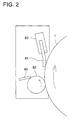
- FIG. 2 shows an example of installing a scraper 89 on the cleaning roller 82.
- the scraper 89 uses such an elastic sheet as phosphor bronze sheet, polyethylene terephthalate sheet or polycarbonate sheet. It may contact the cleaning roller 82 in either the trail method where a tip forms an acute angle on the non-cleaning side of the cleaning roller 82 or the counter method where a tip forms an acute angle on the cleaning side of the cleaning roller 82.
- a roller or brush may be used in addition to said scraper.
- the cleaning system used in the image forming system related to the present embodiment is particularly effective when a photoconductor as an image bearing member as is described below and toner are used.
- an organic photoconductor is considered as providing a good image bearing member.
- the organic photoconductor is represented by the photoconductor obtained by dispersing organic photoconductor in resin.
- This photoconductor consists of an organic compound provided with either electrical charge generation function or electrical charge feed function.
- the surface of the organic photoconductor has less strength, and cannot be subjected to powerful cleaning. If the contact pressure of the cleaning blade widely employed in the cleaning system is made too high, the surface of the organic photoconductor will be worn. To prevent this, the contact pressure is set at a lower value. This makes it difficult to ensure stable cleaning performance for a long time.
- toner used in development is desired to have a volume mean particle size within the range from 3.0 to 8.5 microns, particularly from 3.0 to 6.5 microns.
- the volume mean particle size according to the present invention has been measured by Coulter Counter TA-II or Coulter Multitizer (by Coulter).
- the Coulter Multitizer was used wherein an interface (by Nikkaki) to output the particle size distribution was connected with a personal computer.
- a 100-micron aperture was used in said Coulter Multitizer.
- the volume average particle size was calculated by measuring the volume and quantity of the toner particles each having a diameter of 2 microns or more.
- the toner having such a small particle size is particularly preferred to be the one where particles are formed by polymerization method including emulsion polymerization method, suspension polymerization method or dispersion polymerization method.
- the toner with its particles formed by polymerization method has a narrow distribution of particle size. Its form is not restricted to a spherical form; particles of a desired shape can be obtained.
- Toner whose particles are formed by polymerization includes the following two types. In one type, particles formed by polymerization are directly used as toner particles. In the other type, particles formed by polymerization are combined to form toner particles.
- the toner of small particle size has a problem of difficult cleaning.
- the toner whose particles have been formed by this polymerization method has spherical toner particles in many cases. It has a conspicuous defect of difficult cleaning.
- the embodiment of the present invention provides an excellent cleaning effect when images are formed using the toner of greater particle size produced by pulverization method where toner particles are formed by crushing the resin. Not only that, it provides an excellent cleaning effect for said toner of small particle size, particularly, the tone whose particles are produced by polymerization method.
- charged toner is electrostatically removed by the cleaning roller installed on the upstream side of the cleaning blade.
- Non-charged or reverse-charged toner or fine particles not removed by the cleaning roller are removed by the cleaning blade on the downstream side.
- An effective way of improving cleaning performances is to increase the current value of the bias voltage applied to the cleaning roller.
- cleaning effect by cleaning roller is improved, however, such problems as separation of the cleaning blade and vibration of the tip of the cleaning blade tend to occur in the initial phase of image formation. This is considered to be due to the following reason: Toner working as a lubricant between the image bearing member and cleaning blade is removed by the cleaning roller; hence the amount of toner located at the tip of the cleaning blade is less than that in the conventional cleaning method depending on the cleaning blade alone. This phenomenon occurs particularly in the initial phase of image formation when the contact edge of the cleaning blade is sharp.
- a smaller current is applied to the cleaning roller in the initial phase of image formation, and, in response to increase in the amount of images to be formed, the current value is increased by a control means 85.
- This step ensures excellent cleaning effects throughout the entire image formation process in the present embodiment.
- the amount of images to be formed is preferred to be such that the time assigned for image formation and the number of sheets for formed image can be used.
- the cleaning blade In the initial phase of image formation when a new cleaning blade has been installed, the cleaning blade has excellent cleaning performances. Required cleaning performances can be obtained for an entire cleaning system without having to increase cleaning performances of the cleaning roller.
- Fig. 3 shows an example of the relation between the number of sheets for formed image and the current value of bias voltage applied to the cleaning roller.
- current is increased stepwise from A1 to A3, for example.
- the current value is set back to the initial value at every replacement of the cleaning blade, and is increased in conformity to the number of sheets for formed image. This cycle is repeated.
- the toner used in the present embodiment according to the present invention can be used for both one-component and two-component developers. Furthermore, it can be used as any one of magnetic toner and non-magnetic toner.
- Example 1-1 Same as Example 1-1 except that the traveling speed ratio on the contact surfaces between the cleaning roller and image former is 0.3 to 1.0.
- Example 1-1 Same as Example 1-1 except that the traveling speed ratio on the contact surfaces between the cleaning roller and image former is 2.5 to 1.
- Example 1-1 Same as Example 1-1 except that the contact load of the cleaning blade is 0.5 g/cm.
- Example 1-1 Same as Example 1-1 except that the contact load of the cleaning blade is 35 g/cm.
- Example 1-1 Same as Example 1-1 except that the hardness of the cleaning blade is 10 deg.
- Example 1-1 Same as Example 1-1 except that the hardness of the cleaning blade is 95 deg.
- Example 1-2 As a result of said experiment of image formation in Examples 1-1 and 1-2 according to the present invention, present inventors have obtained excellent images free from contamination or fogging. Especially in Example 1-2, stable cleaning performances without any blade vibration were obtained.
- Embodiment 1 provides the following effects: Uniform excellent cleaning is ensured even if the image bearing member surface potential is not uniform. This makes it possible to configure a highly durable image forming system capable of providing formation of a sharp image free from contamination or fogging.
- Cleaning performances are excellent without damaging the image bearing member even if foreign substances are sandwiched between the image bearing member and cleaning roller.
- Voltage with polarity reverse to that of toner is applied to the cleaning roller 82 by the power supply 84.
- negatively charged photoconductor 1 is reversely developed by negatively charged toner to form an image.
- Said power supply 84 applies to the cleaning roller 82 the voltage with positive polarity reverse to that of the negatively charged toner (hereinafter referred to as "toner-collecting voltage").
- the toner-collecting voltage is used to transfer toner on the photoconductor 1 to the cleaning roller 82 electrostatically. Its polarity is reverse to that of the toner having been involved in development to form images.
- the power supply 84 applies toner-collecting voltage which is controlled by the control means 85 and is increased with the amount of image formed.
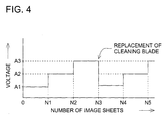
- the power supply 84 is controlled by the control means 85, as shown in Figs. 1 and 4. As a result, voltage increasing with the amount of image formed is applied to the cleaning roller 82.
- the cleaning performance of cleaning roller 82 is increased in response to the increasing amount of image formed, as shown in Fig. 2. Then the load applied to the cleaning blade 81 is reduced in response to the increasing amount of image formed. This ensures the cleaning performance of the entire cleaning system 8 to be maintained throughout the entire image formation process.
- Toner is present between the photoconductor 1 and cleaning blade 81 and is known to work as lubricant. This function of toner allows smooth cleaning to be provided by cleaning blade 81. However, if there is little or no intervention of toner after it has been removed by the cleaning roller 82, a big frictional drag between the photoconductor 1 and cleaning blade 81 will occur. This will result in chattering where the cleaning blade vibrates or curling where the tip portion of the cleaning blade 81 is reversed in response to the photoconductor 1. If the cleaning performance by the cleaning roller 82 is excessive, the amount of said toner as lubricant will be reduced, with the result that chattering or curling tends to occur.
- the voltage applied to the cleaning roller 82 is set at a relatively low value in the initial phase of image formation where the tip edge of the cleaning blade is sharp and curling tends to occur. Said voltage is increased in response to the increasing amount in image formation, thereby ensuring excellent cleaning performance throughout the entire image formation process.
- the bias voltage is controlled as follows; When the number of sheets for formed image has increased from N1 to N3 as shown in Fig. 4, there is a gradual increase of bias voltage from V1 to V3, and the voltage is set back to the initial value V1 by exchange of the cleaning blade.
- Toner-collecting voltage within the range from 0 or floating value to about one third of the maximum value V3 is preferred to be applied as initial value V1.
- An elastic body is used as the cleaning roller 82.
- Rubber including well-known silicone rubber and urethane rubber, foam or foam coated with resin film is desired as a material of such an elastic body.
- the hardness of the cleaning roller within the range from 5 to 60 deg., preferably, 10 to 50 deg. is adequate to get the excellent performance. If the hardness is 5 deg., it is difficult to ensure high durability. If it is higher than 60 deg., it is difficult to secure the width of contact with the image former required for cleaning. In addition, damages tend to occur on the image former surface.
- the hardness is obtained by measuring the elastic body shaped into a roller with an Ascar C hardness meter (load: 300fg).
- the width of the nip when in contact with the image former is desired to be in the range from 0.2mm to 5mm, or preferably 0.5mm to 3mm, although this varies with the roller diameter. If the width is below 0.2mm, cleaning force is insufficient. If it is over 5mm, the image former tends to be damaged at the time of rubbing.
- the cleaning roller 82 is conductive or semiconductive, and is desired to have the surface resistivity ranging from 10 2 ⁇ / ⁇ to 10 10 ⁇ / ⁇ . If the resistivity is below 10 2 ⁇ / ⁇ , banding due to discharge tends to occur. Furthermore, it is higher than 10 10 ⁇ / ⁇ , potential difference is reduced, and cleaning failure tends to occur.
- the surface resistivity ⁇ / ⁇ of the cleaning roller was measured at the normal temperature and relative humidity (26°C, 50% RH) at the applied voltage of 10 volts for the measuring time of 10 sec., using Hirester IP (MCP-HT250) and HA Probe by Mitsubishi Petrochemical Co., Ltd.
- the thickness of the conductive and semiconductive elastic layer is preferred to be set approximately in the range between 0.5 to 50 mm although it varies with the surface resistivity and hardness of the material.
- the cleaning roller 82 is desired to rotate so that the contact portion moves in the same direction as the surface of the photoconductor 1. If said contact portion moves in the reverse direction, the toner removed by the cleaning roller 82 may spill to contaminate the recording paper or the system, when excessive toner is present on the surface of the photoconductor 1.
- the surface speed ratio between the two is desired to be within the range from 0.5:1 to 2:1. Outside this range, the photoconductor may be damaged if the difference of their speeds increases, and recording paper or other foreign substance is sandwiched between the photoconductor 1 and cleaning roller 82.
- Fig. 2 shows an example of the scraper 89 installed on the cleaning roller 82.
- the elastic plate such as phosphor bronze plate, polyethylene terephthalate plate or polycarbonate plate is used as the scraper 89. It may contact the cleaning roller 82 using either the trail system where the tip edge forms an acute angle on the uncleaned side of the cleaning roller 82 or the counter system where the tip forms an acute angle on on the cleaned side of the cleaning roller 82.
- a roller and brush in addition to said scraper can be used to remove the toner and foreign substances transferred from the cleaning roller 82 to the cleaning roller 82.
- the cleaning system used in the image forming system according to the present embodiment is especially effective when the image bearing member and toner to be described below is used.
- organic photoconductor is useful as the image bearing member.
- the organic photoconductor is represented by the photoconductor produced by an organic photoconductor dispersed in resin, where the organic compound is provided with either electrical charge generation function or electrical charge feed function.
- the surface of the organic photoconductor has a low strength, which makes it difficult to use powerful cleaning capacity. If the contact pressure of the cleaning blade extensively used as a cleaning system is excessive, contact pressure is kept low by the wear of the organic photoconductor surface. This makes it difficult to ensure stable cleaning performance for a long time.
- the preferred toner used for development has a volume mean particle size ranging from 3.0 to 8.5 microns, more preferably from 3.0 to 6.5 microns.
- the volume mean particle size of the toner according to the present invention is measured by the Coulter Counter TA-II or Coulter Multitizer (by Coulter).
- the Coulter Multitizer was used for measurement, and the interface (by Nikkaki) to output the data on particle size distribution was connected with a personal computer.
- a 100-micron aperture was used in said Coulter Multitizer to measure the volume and number of the tone particles of 2 microns or more, thereby calculating the volume mean particle size.
- the toner having such a small particle size is particularly preferred to be the one where particles are formed by polymerization method including emulsion polymerization method, suspension polymerization method or dispersion polymerization method.
- the toner with its particles formed by polymerization method has a narrow distribution of particle size. Its form is not restricted to a spherical form; particles of a desired shape can be obtained.
- the toner of small particle size has a problem of difficult cleaning.
- the toner whose particles have been formed by this polymerization method has spherical toner particles in many cases. It has a conspicuous defect of difficult cleaning.
- the embodiment of the present invention provides an excellent cleaning effect when images are formed using the toner of greater particle size produced by pulverization method where toner particles are formed by crushing the resin. Not only that, it provides an excellent cleaning effect for said toner of small particle size, particularly, the tone whose particles are produced by polymerization method.
- Toner whose particles are formed by polymerization includes the following two types. In one type, particles formed by polymerization are directly used as toner particles. In the other type, particles formed by polymerization are combined to form toner particles.
- the toner used in the present embodiment according to the present invention can be used for both one-component and two-component developers. Furthermore, it can be used as any one of magnetic toner and non-magnetic toner.
- Embodiment 3 where excellent cleaning performances without chattering and curling of the cleaning blade can be ensured.
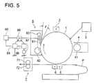
- Fig. 5 shows the image forming system according to the Embodiment 3.
- power supplies 84 and 86 each having a reverse polarity with the other are connected to the cleaning roller 82 through temporal selection.
- the power supply 84 applies to the cleaning roller 82 the toner-collecting voltage which transfers the charged toner on the photoconductor electrostatically to the cleaning roller 82.
- the power supply 86 applies the voltage which transfers the charged tone on the cleaning roller 82 to the photoconductor 1.
- the power supply 86 applies the toner-releasing voltage.
- the polarity of the toner-releasing voltage is reverse to that of the toner-collecting voltage.
- Such a toner-releasing voltage is applied when cleaning by the cleaning roller 82 is not interfered.
- toner-releasing voltage be applied at periodic intervals so that toner-releasing voltage is applied at every formation of 10 to 1000 sheets of image as to the number of sheets for formed image.
- the periodic intervals of application of toner-releasing voltage can be changed in response to the volume of image to be formed.
- excellent cleaning effect can be obtained by application of toner-releasing voltage at every formation of 1000 sheets of image in the initial phase, and at every formation of 500 sheets after formation of 100,000 sheets of image.
- images can be formed while toner-releasing voltage is applied.
- toner-releasing voltage is desired to be 1.2 times the white background potential.
- the white background voltage is -750 volts
- voltage of -750 to-2250 volts is preferred.
- the voltage equivalent to 1/10 to 5 times the white background voltage is preferred in the image formation process based on normal development.
- lower voltage namely, reversal development is used to prevent discharge in the image formation system where discharge is likely to occur
- 1 to 1.5 times the white background potential is preferred.
- 1/3 to 2/3 times the black background potential is preferred in particular.
- toner-releasing voltage it is also possible to apply the bias voltage obtained from a.c. voltage from the power supply 87 superimposed on the d.c. voltage from the power supply 86.
- Application of a.c. voltage provides an effective means for discharging toner from the cleaning roller 82 to the photoconductor 1. It is particularly desirable to use a.c. voltage within the frequency range from 0.5 kHz to 20 kHz. Further, as amplitude of the a.c. voltage, 1/3 to 2 times the white background potential is desirable in terms of peak-to-peak voltage in the image formation system based on reversal development. In the image formation system based on normal development, 1/3 to 2 times the black background potential is desirable.
- Embodiments 2 and 3 are also effective in improving the cleaning performances.
- the power supply 84 and switch 88 is controlled by the control means 85 in such a way that the toner-collecting voltage is increased in response to the increasing number of sheets for formed image, and toner-releasing voltage is applied to the cleaning roller 82 at periodic intervals, thereby ensuring an excellent cleaning effect.
- periodic intervals for application of toner-releasing voltage can be changed in response to the amount of formed image.
- Example 2-2 +600-volt toner-collecting voltage was applied to the cleaning roller throughout the entire image formation process, and 500-volt peak-to-peak voltage and 2kHz-frequency a.c. voltage superimposed on - 1000-volts d.c. voltage were applied as toner-releasing voltage in the following manner at periodic intervals:
- Said toner-releasing voltage was applied in the formation of one sheet of image for every 1000 sheets in the range from 0 to 50,000 sheets, said toner-releasing voltage in the formation of one sheet of image for every 500 sheets in the range from 50,001 to 100,000 sheets, and said toner-releasing voltage in the formation of one sheet of image for every 100 sheets in the range from 100,001 to 150,000 sheets. Two cycles of said toner-releasing voltage application were repeated twice to form 300,000 sheets of image. In Example 2-3, the following toner voltages were applied:
- Example 2-2 The same toner discharge electric field as in the case of Example 2-2 was applied at the same timing as the Example. A total of 300,000 sheets of image were formed by two cycles of said step.
- the test environment was the same as those in Examples 2-1 and 2-2; normal temperature and humidity (20°C, 50% RH) up to 50,000 sheets and high temperature and humidity (30°C, 80% RH) from 50,001 to 150,000 sheets. A total of 300,000 sheets of image were formed by two cycles of said step.
- test environment was the same as that in Example 1; normal temperature and humidity (20°C, 50% RH) up to 50,000 sheets and high temperature and humidity (30°C, 80% RH) from 50,001 to 150,000 sheets.
- Image formation was conducted under the same conditions as the Example except that + 600-volt toner-collecting voltage was applied to the cleaning roller throughout the entire image formation process. In the Reference Example, toner-releasing voltage is not applied.
- Examples 2-1 and 2-2 stable excellent cleaning performances were ensured without image failure caused by curling and chattering of the cleaning blade or wear of the photoconductor, until formation of 300,000 sheets of image was completed.
- Example 2-3 stable excellent cleaning performances were ensured without image failure caused by curling of the cleaning blade or wear of the photoconductor, particularly without any chattering of the blade under the conditions of high temperature and humidity, until formation of 300,000 sheets of image was completed.
- Cleaning performances are excellent without damaging the image bearing member even if foreign substances are sandwiched between the image bearing member and cleaning roller.
- Voltage having a polarity reverse to that of the toner is applied to the cleaning roller 82 by the power supply 84.
- Said power supply 84 applies to the cleaning roller 82 the voltage with positive polarity reverse to that of the negatively charged toner (hereinafter referred to as "toner-collecting voltage").
- the toner-collecting voltage is used to transfer toner on the photoconductor 1 to the cleaning roller 82 electrostatically. Its polarity is reverse to that of the toner having been involved in development to form images.
- the power supply 84 applies toner-collecting voltage which is controlled by the control means 85 and is increased with the amount of image formed.
- Particles of toner charged in the same polarity as that of the toner involved in the development device 4 in such a great variety of deposits are removed electrostatically by the cleaning roller 82.
- the non-charged toner, reversely charged toner and other particles which can not be removed by the cleaning roller 82 are removed mechanically by the cleaning blade 81.
- Embodiment 4 is intended to carry out electric cleaning (by a roller) to remove the greater part of the remaining toner.
- a means of mechanical cleaning (by a blade) is used to eliminate a very small amount of toner which cannot be removed electrostatically due to charging failure or charging in reverse polarity resulting from transfer.
- Application of bias to the cleaning roller at this time is started later than start of image former traveling or application of bias to the development device. It terminates later than termination of application of bias to said development device and earlier than termination of said image former traveling.
- bias is applied when image formation stops, bias is applied to the same position of the image former for a long time. As a result, discharge tends to occur between that position and the roller, damaging both the image former and roller. Mechanical damage also tends to occur. To avoid overshooting of bias application, bias is preferred to be applied to the cleaning roller after start of image former movement or during its movement.
- the time of apply bias to the cleaning roller be delayed by application of bias to the development device, and bias be applied to the roller after the image former area to which foreign substances are deposited has passed through the roller section. Then foreign substances are mechanically scraped off by the downstream cleaning blade.
- the cleaning roller When application is stopped, the cleaning roller is located on the downstream side of the development device. Accordingly, in order to remove the developer on the image former between the development device and cleaning device from the time of stopping application of bias to the development device, it is basically necessary to stop application of bias to the cleaning roller after the lapse of time for the image former to travel between the development device and cleaning device.
- image former traveling is desired to be stopped after termination of the bias application, with consideration given to the falling time of bias applied to the cleaning roller.
- the actual blade load is 1 to 30 grams/cm, or preferably, 10 to 25 grams/cm. When it is below 1 grams/cm, cleaning force is insufficient, and a small amount of toner which cannot be removed by the roller may not be completely removed. When it is 30 grams/cm or more, the wear of the image former surface will increase, and fogging or blurring of image may occur after a long-term use.
- the angle ⁇ between the surface of said cleaning blade facing the image former, and the surface of said image former including said contact point between the cleaning blade and image former where said blade has passed is desired to be in the range from 0 to 40°C, more preferably from 0 to 25°C. When it is smaller than 0 deg., cleaning force is reduced. If it is greater than 40 deg., blade curling tends to occur, where the blade tip follows the travel of the image former and the blade is curled (See Fig. 1).
- the blade can be supported by either stationary or rotary method if the angle between the load and blade is within the above range.
- the rubber hardness of said cleaning blade is desired to be 20 to 90 deg., more particularly, 60 to 80 deg. If it is below 20 deg., the blade is too soft, and curling and cleaning failure tend to occur. If it is over 90 deg., the blade is too hard, and the blade cannot respond to a slight amount of foreign substances deposited on the image former. As a result, escape of toner particles tends to occur.
- the hardness of the blade is measured according to JIS K 6253.
- Polyurethane and other materials known in the conventional technology can be used as a material for the blade. There is no resctriction if blade thickness, free length, load and angle are within said range. To ensure good load controllability and to avoid curling, the thickness is desired to be within the range from 1 to 3mm, or preferably from 1.5 to 2.5mm. The desirable free length is from 2 to 20mm, or preferably from 3mm to 15mm.
- bias is applied to the cleaning roller by power supply 84 (numeral 85 denotes its control means).
- Said power supply is preferred to be a constant current power supply.
- What is called constant current power supply hereunder is a power supply which is controlled to ensure that a constant current is issued at a1 times in the stable output range.
- the polarity of the bias applied for cleaning is reverse to that of the tone used to create visible images. Namely, when toner is negatively charged, positive bias is applied to the cleaning roller. If bias is applied by the constant current power supply in this case, potential difference to feed a constant current at all times necessarily occurs to the roller surface and image former surface. This potential difference occurs constant at all times in response to the potential on the image former. Accordingly, compared to the case when the constant voltage power supply is used, irregularity due to the potential level of the image former and polarity or cleaning failure occur very infrequently.
- application of bias to this cleaning roller starts later than the start of image former traveling or application of bias potential to said development device, and terminates later than termination of application of bias to said development device, and earlier than suspension of said image former movement.
- the traveling rate of this image former is 400mm/sec and image formation (start of development on the image former to the latent image) is carried out 1000ms after application of bias to the development device in an image forming system
- application of bias to the cleaning roller can be started 200 to 1200ms after application of bias to the development device.
- bias is preferred to be applied after the rising time of development bias power supply (200 ms in this case).
- a delay of approximately 10 to 200 ms (210 to 400 ms in this case) is preferred in this case although it varies with the power supply.
- the cleaning roller When application is stopped, the cleaning roller is located on the downstream side of the development device. Accordingly, in order to remove the developer on the image former between the development device and cleaning device from the time of stopping application of bias to the development device, it is basically necessary to stop application of bias to the cleaning roller after the lapse of time for the image former to travel between the development device and cleaning device (200ms in this case).
- image former traveling is desired to be stopped 10 to 1000 ms after termination of the bias application, with consideration given to the falling time of bias applied to the cleaning roller.
- timing to apply bias to the cleaning roller is preferred to be determined in conformity to development bias timing in the case of an image forming system of other linear velocity.
- a preferred current value to be applied is 1 to 50 microamperes in terms of absolute value. If it is below 1 microampere, cleaning will be insufficient. If it is over 50 microamperes, discharge will tend to occur. Although it varies with the thickness of the image former film and resistance of the cleaning roller, this value is 15 to 30 microns -- equivalent to the film thickness of the organic photoconductor dispersed in isolating resin as an image former. When the roller surface resistivity of 10 2 ⁇ / ⁇ to 10 10 ⁇ / ⁇ is used, it is preferred to apply 5 to 40 microamperes in terms of absolute value.
- the roller is made of an elastic body to ensure good contact with the image former.
- an elastic body can be made of rubbers such as silicone rubber and urethane rubber as is known in the art heretofore, foams or foams coated with resin film.
- the surface resistivity of the roller is desired to be 10 2 ⁇ to 10 10 ⁇ / ⁇ , as described above. If the value is greater than 10 10 ⁇ / ⁇ , potential difference required to eliminate the toner cannot be obtained. If it is smaller than 10 2 ⁇ / ⁇ , discharge due to banding or others will tend to occur.
- the surface resistivity ( ⁇ / ⁇ ) of the cleaning roller was measured at the normal temperature and relative humidity (26°C, 50% RH) at the applied voltage of 10 volts for the measuring time of 10 sec., using Hirester IP (MCP-HT250) and HA Probe by Mitsubishi Petrochemical Co., Ltd. To ensure adequate resistance and nip width, the thickness of the conductive and semiconductive elastic layer is preferred to be set approximately in the range between 0.5 to 50 mm although it varies with the surface resistivity and hardness of the material.
- the hardness of said cleaning roller is desired to be 5 to 60 deg., more particularly, 10 to 50 deg. If it is below 5 deg., durability will be poor. If it is over 60 deg., the width for contact with the image former required for cleaning will be difficult and the image former surface tends to be damaged.
- the hardness is obtained by measuring the elastic body shaped into a roller with an Ascar C hardness meter (load: 300fg).
- the width of the nip when in contact with the image former is desired to be in the range from 0.2mm to 5mm, or preferably 0.5mm to 3mm, although this varies with the roller diameter. If the width is below 0.2mm, cleaning force is insufficient. If it is over 5mm, the image former tends to be damaged at the time of rubbing.
- the contact portion of the cleaning roller is desired to move in the same direction as the image former. If it moves in the reverse direction, the recovered toner may spill on the transfer unit when excessive toner is present on the surface of the image bearing member (transfer failure or occurrence of jam).
- the peripheral speed ratio with the image former and the roller is desired to be within the range from 0.5:1 to 2:1. If it is below 0.5, cleaning capacity tends to reduce. If it is over 2, the image former tends to be damaged when foreign substances are sandwiched in-between.
- the toner removed by the cleaning roller electrostatically is scraped off by a scraper 89 in contact with the roller.
- the scraper can be located in either the counter or trail direction with respect to the roller.
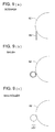
- a phosphor bronze plate, polyethylene terephthalate plate, polycarbonate plate or their combination known in the conventional technology can be used as the material for the scraper. This is not restricted to the scraper; a bias roller and fur brush can be used (see Figs. 9(a), 9(b) and 9(c)).
- the toner collected by these cleaning system can be reused after being fed back to the development device.
- the toner with a volume mean particle size of 8.5 microns or less, more preferably, 6.5 microns or less which has been manufactured by so called polymerization method wherein tone particles of a desired diameter can be obtained during the production of binding resin, without using the kneading and pulverizing process. Further, to ensure good toner charging stability at the time of development, use of toner with a particle size of 3 microns or more is desired.
- Tone particles can be made by any one of emulsion polymerization method, suspension polymerization method or dispersion polymerization method known in the conventional technology. Even if toner particles are almost spherical, cleaning failure does not occur according to the present invention. If only the desired particle size is secured, there is no need of making toner particles indefinite.
- the toner produced according to the conventional pulverization method can be used for the present invention. To make full use of excellent performance of the present invention, it is preferred to use the toner manufactured by the polymerization method.
- the volume mean particle size of the toner according to the present invention is measured by the Coulter Counter TA-II or Coulter Multitizer (by Coulter).
- the Coulter Multitizer was used for measurement, and the interface (by Nikkaki) to output the data on particle size distribution was connected with a personal computer.
- a 100-micron aperture was used in said Coulter Multitizer to measure the volume and number of the tone particles of 2 microns or more, thereby calculating the volume mean particle size.
- Embodiment 5 is the same as that of Embodiment 4 in that electric cleaning is carried out (by a roller) to remove the greater part of the remaining toner, and a means of mechanical cleaning (by a blade) is used to eliminate a very small amount of toner which cannot be removed electrostatically due to charging failure or charging in reverse polarity resulting from transfer.
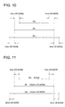
- Embodiment 5 is further characterized by: W2 ⁇ W1 ⁇ W3 (See Fig. 10) where;
- W1 > W3 on the substrate of the image former electric discharge will occur from the cleaning roller with the result that the cleaning performance is seriously deteriorated. If W1 ⁇ W2, toner will scatter from the development device, and toner deposited outside the range of the cleaning roller cannot be removed. Hence, W2 ⁇ W1 ⁇ W3 is preferred.
- W1 is preferred to be at least 3 mm or preferably at least 7 mm greater than W2 on both sides (see Fig. 10). If there are much toner on the image former which cannot be recovered, the charged electrode and optical system will be contaminated, and such image failure as fogging or white streak will be observed.
- W1 is preferred to be at least 2 mm or preferably at least 6 mm smaller than W3 on both sides (see Fig. 10). If there is electric discharge to conductive substrate of the image former, current will flow in that portion and the potential difference required for cleaning does not occur on the cleaning surface. As a result, cleaning failure tends to be observed.
- W2 is 300mm
- W1 is at least 306 mm, at least 3mm greater than W2 on both sides.
- the width of photosensitive layer W3 is set to at least 310 mm, at least 2 mm greater than W1 on both sides. (See Fig. 11).
- the width of the cleaning blade is preferred to be the same as that of the cleaning roller. No problem arises if there is a difference of about 5mm on both sides for mechanical designing requirements.
- the cleaning blade load and its components are the same those in Embodiment 4.
- Embodiment 4 The components, application potential level and polarity are the same those in Embodiment 4.
- the image former disclosed in Japanese Patent Laid-Open NO.216172/1989 can be used as material.
- the same toner as used in the Embodiment 4 can be used.
- the development method can be used without any restriction as in the case of Embodiment 4.
- the evaluation device used in the experiment has the same configuration as that of the image forming system shown in Fig. 1, and is based on the reversal development method where a latent image is formed by erasing the potential of the image section on the image former through laser exposure.
- Image former lineal velocity during image formation is 240mm/sec.
- Negatively charged toner having a mean volume particle size of 6.5 microns obtained by emulsion polymerization method was used for two-component developer toner.
- the photoconductor layer including the electrical charge feed layer is 25 microns thick, with a charged potential of - 750 volts on the non-image section and a potential of -100V on the darkest image portion.
- the peripheral speed ratio at the contact portion of the image former was approximately 1 to 1. It is rotated synchronously with the image former by a gear couple. Further, the roller is installed so that the nip width in contact with the image former is 2mm, and is formed by winding an urethane layer on a 6mm-diameter metallic shaft to a thickness of 4.5mm. (roller: 15mm in diameter)
- This roller was designed to turn in the same direction as the image former at the nip section.
- a scraper was provided to remove the recovered toner.
- the current of +20 microamperes was applied from the constant current power supply.
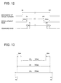
- Fig. 12 shows the bias application timing.
- the bias rise time (including overshoot) and fall time each were 10 ms.
- the cleaning blade was made of urethane rubber. It had a hardness of 70 deg. with a thickness of 2.00mm and a free length of 10mm. This blade was installed to be in contact with the image former at an angle of 10 deg. with a contact load of 120 mN/cm.
- the evaluation device is designed based on the reversal development method where a latent image is formed by erasing the potential of the image section on the image former through laser exposure.
- width of developer feed is W2
- cleaning roller width is W1
- width of photosensitive layer on the image former is W3
- width of cleaning blade is the same as W1, as shown in Fig. 13.
- Negatively charged toner having a mean volume particle size of 6.5 microns obtained by emulsion polymerization method was used for two-component developer toner.
- the photoconductor layer including the electrical charge feed layer is 25 microns thick, with a charged potential of -750 volts on the non-image section and a potential of -100V on the darkest image portion.
- the peripheral speed ratio at the contact portion of the image former was approximately 1 to 1.
- This roller was designed to move in the same direction as the image former at the nip portion.
- a scraper was provided to remove the toner. It was designed that the nip portion in contact with image former was 2mm wide, and was formed by winding an urethane layer on a 6mm-diameter metallic shaft to a thickness of 4.5mm. (roller: 15mm in diameter)
- a current of +20 microamperes was applied from the constant current power supply.
- the cleaning blade was made of urethane rubber. It had a hardness of 70 deg. with a thickness of 2.00mm and a free length of 10mm. This cleaning blade was brought in contact with the image former at a contact angle of 10 deg. with a contact load of 120mN/cm.
- Embodiment 4 of the present invention provides an image forming system which ensures stable high quality images for a long time free from damage by electric discharge.
- Embodiment 5 of the present invention provides an image forming system provided with a cleaning system which ensures stable cleaning performances for a long time, while recovering the toner extensively scattered from the development device.
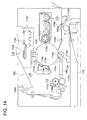
- numeral 110 denotes a photoconductor drum as an electrostatic latent image bearing member, For example, it is composed of a conductive drum coated with an OPC photoconductor comprising an organic photoconductive layer. It is grounded, and is driven and rotated in the clockwise direction.
- Numeral 111 denotes a charging device which provides uniform negative electric charging, for example, on the circumferential surface of the photoconductor drum 110 by corona discharge, thereby providing potential V H . Prior to electric charging by said charging device 111, exposure is carried out by PCL 11a using a light emitting diode or the like in order to remove the history of the photoconductor up to the previous printing. Thus, electric charge is eliminated from the surface on around the photoconductor.
- the image is exposed by the laser writer 112 based on image signal.
- image signals entered from a computer or image reader have been processed by the image signal processor, data on this image exposure is entered into the laser writer 112, and an electrostatic latent image is formed on the photoconductor drum 110.
- the optical path is bent by multiple reflecting mirror M 112d through a f ⁇ lens 112c and a rotating polygon mirror 112b which is rotated using a laser diode (not illustrated) as a light emitting light source, and horizontal scanning of the laser writer 112 is performed.
- An electrostatic latent image is formed by said horizontal scanning and vertical scanning due to rotation of the photoconductor drum 110.
- image section is subjected to exposure based on said image signals. Then a reversal latent image is formed and the potential of the exposure unit becomes V L , where the absolute value of the potential is low.
- a development device 113 is installed on the periphery of the photoconductor drum 110, wherein said development device contains negatively charged conductive toner and a built-in two-component developer composed of a magnetic carrier. Reversal development is carried out by a rotating development sleeve 113a which contains a built-in magnet and holds the developer.
- the developer is produced in such a way that electric charge controlling agent, silica, titanium oxide or the like is added to a carrier using Ferrite as a core around which insulating resin is coated and the toner provided with such a coloring agent as pigment or carbon black, and they are mixed so that toner concentration will be from 5 to 10 wt. %, wherein said toner having a weight mean particle size (discussed later) of 3 to 10 microns.
- the developer is controlled to the layer thickness of 0.1 to 0.6mm on the development sleeve 113a, and is fed to the development area.
- the space between the development sleeve 113a and photoconductor drum 110 in the development area is 0.2 to 1.0 microns -- a value greater than the thickness of the developer layer.
- the a.c. bias voltage obtained by superimposing the a.c. voltage VAC onto the d.c. voltage V DC is applied between the development sleeve 13a and photoconductor drum 110.
- Toner is negatively charged in the same polarity as the d.c. voltage V DC . Accordingly, the toner provided with the chance of getting separated from the carrier by the a.c. voltage V AC does not deposit on the portion V H where the absolute value of the potential is higher than the d.c. voltage V DC .
- the amount of toner in conformity to the potential difference is deposited on the portion V L where the absolute value of the potential is lower, thereby resulting in reversal development. Further, only the d.c. voltage V DC can be applied between the development sleeve 113a and photoconductor drum 110. Contact development can be performed as development. The photoconductor drum 110 holding the toner image performs transfer operations in the next transfer step.
- the recording paper is fed to a timing roller 15d by a paper feed cassette 115 through a semi-circular roller 115a and feed rollers 115b and 115c, and is stopped there once. Then when the system is ready for transfer, said paper is fed to a transfer area 4b by the rotation of a timing roller 115d. Synchronously with transfer, a transfer roller 114a to which a high voltage charged in the polarity reverse to that of toner is applied by a high pressure power supply 134 is brought in contact with the circumferential surface of the photoconductor drum 110 at a transfer area 114b. With the fed recording paper P in-between, the toner image on the circumferential surface of the photoconductor drum 110 is transferred to the recording paper P.
- Electric charge is eliminated by peak electrodes 114c laid out with a slight gap from the recording paper P where a toner image is transferred.
- Said paper is separated from the circumferential surface by means of a photoconductor drum 110, and is fed to a fusing device 117 by a feed belt 116.
- the transfer toner image is molten by heating and pressure of the fusing roller 117a as a heating roller and pressure roller and fusing roller 117b.
- the paper is ejected to the tray unit 50 by the ejecting rollers 18a and 18b.
- said transfer roller 14a is kept separated from the circumferential surface of the photoconductor drum 110 until the next image image transfer.
- the photoconductor drum 110 After having transferred the toner image to the recording paper P, the photoconductor drum 110 reaches the cleaning system 119.
- the greater part of toner remaining on the surface is removed by being sucked to tone recovery roller 19b as a toner recovery means consisting of e.g. the conductive elastic roller to which constant current bias voltage to be discussed later is applied from the constant current high voltage power supply 35.
- the deposited amount of toner per unit area on the photoconductor drum 10 is reduced to 0.25 mg/cm 2 or less.
- the toner remaining on the circumferential surface is scraped off into the cleaning system 119 by the cleaning blade 119a consisting of a urethane rubber material in contact with the photoconductor drum 110.
- the toner moved to said toner recovery roller 119b by the blade 119e is also scraped off into the cleaning system 19 and is ejected or stored by the screw or the like.
- the photoconductor drum 110 from which the remaining toner has been removed by the cleaning system 119 is exposed by the PC L 111a. Then it is uniformly charged by a charging device 111, and the next image formation cycle.
- Toner of the developer used in the image forming system of said the present invention for example, is polymerized toner produced by emulsion polymerization association method, and has an approximately circular form with a mean circularity of 0.96 to 0.99.
- the mean circularity hereunder can be defined by a means value of m/M where M represents the circumferential length of the projected image of the toner particle, and m denotes the circumferential length of the equivalent circle having the same area as that of the projected image of the toner particle.
- Circularity is 1 when the particle image is truly circular, and the value is smaller as the particle image is more slender or more irregular in shape.
- Polymerized toner is produced by emulsion polymerization association method as follows: The surfactant is used to to disperse coloring agent in water. In the meantime, surfactant, emulsion polymerization initiator, styrene monomer and acryl monomer are placed in water to produce resin emulsion by emulsion polymerization. Then said coloring agent dispersant and resin emulsion are mixed. While keeping balance between the repulsive force of the particles surface generated by PH regulation and coagulation force by addition of electrolyte, gradual coagulation is carried out. Association is allowed to take place while controlling particle size and particle size distribution, and heating and agitation are implemented at the same time. In this manner, inter-particle fusing and shape control are performed.
- inter-particle fusing and shape control is implemented using an agitation tank designed to ensure that agitation is carried out in a laminar flow free from turbulent flow.
- a flow type particle image analyzer FPIA-2000 (by Toa Medical Electronics) is used to measure the mean circularity. This analyzer allows the shape of the particle to be monitored during generation of toner particles. So reaction can be stopped when a desired mean circularity and weight mean particle size has been obtained. Obtained particles are filtered, cleaned and dried, thereby getting toner particles having a mean circularity of 0,96 to 0.99 and a weight mean particle size (D50) of 3 to 10 microns.
- the weight mean particle size (D50) was measured by the Coulter Counter TA-II (by Coulter).
- Toner obtained in said manner according to emulsion polymerization association method is characterized by a sharp distribution of particle size and a small amount of fine particles, very small contamination of the carrier by toner ("Toner spent"), excellent developer durability and uniform distribution of charged amount. Images of high quality are ensured as compared to those obtained from the conventional pulverization system.
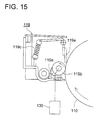
- Fig. 15 is a cross sectional view representing an example of the cleaning system of the image forming system shown in Fig. 14 according to the present invention.
- numeral 110 denotes a photoconductor drum
- 119 indicates a cleaning system.
- Numeral 119a represents a cleaning blade comprising a urethane rubber having a rubber hardness of JISA 69 deg., a free length of 9mm and a thickness of 2mm
- 119b denotes a 15mm-diameter conductive and elastic toner recovery means which is a toner recovery roller made of conductive urethane comprising a RUBISEL roller having a hardness Ascar C 32 deg. (by Toyo Polymer), for example.
- Numeral 119c indicates an energizing member such as a spring
- 119e denotes a blade to scrape off the toner having moved onto the toner recovery roller 119b.
- Cleaning blade 119a is an elastic blade installed in a counter form. It is brought in contact with the surface of the photoconductor drum 110 by means of an energizing member 119c so that normal load is 20 to 22mN/cm.
- the toner recovery roller 119b is brought in light contact with the surface of the photoconductor drum 110, and follows the rotation of the photoconductor drum 110. Voltage of the reverse polarity to toner is applied to the recovery roller 119b from thee constant current high voltage power supply 135 of the constant current control. Constant current bias voltage is applied to ensure that the remaining toner passing through without being recovered by the toner recovery roller 119b will not exceed 0.25mg/cm 2 .
- Fig. 16 is a chart representing the relation of the amount of deposited toner passing through without being recovered by the toner recovery roller 119b when the amount of deposited toner of 0.75 mg/cm 2 per area corresponding to untransferred solid black where the amount of toner deposited on the surface of the photoconductor drum 110 is the maximum is fixed unchanged, and the current value of the constant current bias voltage to be applied to the toner recovery roller 119b is changed.
- Fig. 16 shows that constant current bias voltage of 15 microamperes or more must be applied in order to ensure that the amount of toner deposited after passing through the toner recovery roller 119b does not exceed 0.25 mg/cm 2 .
- constant current bias voltage of 15 microamperes or more is applied, thereby ensuring that the amount of deposited toner on the photoconductor drum 110 passing through the recovery roller 119b and reaching the cleaning blade 119a does not exceed 0.25 mg/cm 2 .
- the amount of deposited toner on the photoconductor drum 110 passing through the recovery roller 119b and reaching the cleaning blade 119a was changed in the following order; 0.60, 0.53, ..., 0.20, 0.10 mg/cm 2 or less. In this case, a test was made to check if cleaning by the cleaning blade 119a was satisfactory or not. The result of this test is given in Table 1.
- the inventors of the present invention prepared 15 types of toner as combinations of five types of mean circularity; 0.95, 0.96, 0.97, 0.99, and 1.00 and three weight mean particle sizes; 3, 6 and 10 microns.
- the amount of deposited toner on the photoconductor drum 110 having passed through the recovery roller 119b and reached the cleaning blade 119a was adjusted not to exceed 0.20, 0.25, ..., 0.27 microns per unit area.
- 110 kP printing test was conducted using image forming system shown in Fig. 1. Table 2 shows the result of this test.
- Amount of toner deposited before blade Toner Cleaning performance Average circularity Weight mean particle size 0.20 0.95 3 good passable (1) Not the present invention 6 good passable 10 good passable 0.96 3 good good (2) Not the present invention 6 good good 10 good good 0.97 3 good good (3) Not the present invention 6 good good 10 good good 0.99 3 good good (4) Not the present invention 6 good good 10 good good 1.00 3 bad bad (5) Not the present invention 6 passable passable 10 good good 0.25 0.97 3 good good (6) Not the present invention 6 good good 10 good 0.27 0.97 3 bad bad (7) Not the present invention 6 passable passable 10 good good Amounts of toner deposited are given in terms of mg/cm 2 .
- Weight mean particle sizes are given in microns.
- Adjustment was made so that the amount of deposited toner immediately before the cleaning blade 119a did not exceed 0.20 mg/cm 2 , and tests ⁇ 2>, ⁇ 3> and ⁇ 4> were conducted using three types of mean circularity; 0.96, 0.97, and 0.99. These tests revealed that both cleaning performance and image quality were satisfactory.
- test ⁇ 6> was conducted using the mean circularity of 0.97. This test revealed that both cleaning performance and image quality were satisfactory.
- the results of tests ⁇ 2>, ⁇ 3> ⁇ 4> and ⁇ 6> in the present invention were satisfactory in both cleaning performance and image quality.
- test ⁇ 1> was conducted using the mean circularity of 0.95. The test revealed that cleaning performance was satisfactory without any problem, but irregularities on image surface probably caused by development were found out.
- Adjustment was made so that the amount of deposited toner immediately before the cleaning blade 119a did not exceed 0.20mg/cm 2 , and test ⁇ 5> was conducted using the mean circularity of 1.00. In this test cleaning failure was detected, and fogging phenomenon was observed. This phenomenon occurred especially when small-diameter toner particles having a weight mean particle size of 3 microns were used. Probably some of them passed through the blade, resulting in this phenomenon.
- Adjustment was made to ensure that the amount of deposited toner immediately before the cleaning blade 119a did not exceed 0.27mg/cm 2 , and test ⁇ 7> was conducted using the mean circularity of 0.97. In this test, cleaning failure was observed. Fogging phenomenon and toner contamination were observed especially when small-diameter toner particles having a weight mean particle size of 3 microns were used.
- an image forming system is equipped with a cleaning system 119 wherein constant current bias voltage having a current of 15 microamperes or more is applied to the toner recovery roller 119b by the constant current high voltage power supply 135.
- the surface of the photoconductor drum 110 reaches the cleaning system 119 after a formed toner image is transferred onto the recording paper P, and toner image remaining untransferred due to jamming or other reasons reaches the cleaning system 119.
- the remaining toner is fed to the toner recovery roller 19b by bias voltage applied to the remaining toner recovery roller 119b, and is reduced so that the amount of deposited toner does not exceed 0.25 mg/cm 2 .
- the toner having moved to said toner recovery roller 119d is scraped off by the blade 119e, and ejected or stored into a toner waste storage tank (not illustrated) by the screw or the like together with the toner having been scraped off by said cleaning blade 119a.
- Fig. 17 is a cross sectional view representing the configuration of another example of a cleaning system 119A in the image forming system according to the present invention.
- Numeral 119d denotes a toner recovery fur brush as an toner recovery means. It is a toner recovery fur brush for toner collection, for example, consisting of the conductive viscose rayon REC, SH (300/100, D/F, 224kF/inch 2 ) by Toa Sangyo, having a shaft diameter of 11 mm and brush diameter of 20mm with 4.5 mm-long hair around the shaft.
- the hair tip of the toner recovery fur brush 119d lightly contacts the surface of the photoconductor drum 110, and the contact portion is rotated by electric power (not illustrated) in the same direction as the photoconductor drum 110.
- Bias voltage of constant current having a current value of 15 microamperes or more, for example, is applied to the toner recovery fur brush 119d by means of a constant current high voltage power supply 135, as in the case of said toner recovery roller 19b illustrated in Fig. 15.
- the surface of the photoconductor drum 110 reaches the cleaning system 119 after a formed toner image is transferred onto the recording paper P, and toner image remaining untransferred due to jamming or other reasons reaches the cleaning system 119.
- the remaining toner is reduced so that the amount of deposited toner does not exceed 0.25 mg/cm 2 . So the remaining toner is scraped off by the cleaning blade 119a without escape of toner particles, thereby ensuring perfect cleaning.
- the toner having moved to said toner recovery fur brush 119b is scraped off by the blade 119e, and is ejected or stored into a toner waste storage tank (not illustrated) by the screw or the like together with the toner having been scraped off by said cleaning blade 119a.
- Embodiment 6 provides an image forming method and image forming system which ensure excellent images for a long time without toner passing through the cleaning blade despite the use of approximately circular toner of small particle size, or without deterioration of cleaning performance. This makes it possible to provide an image forming system characterized by high quality printing without particles being noticeable.
- Fig. 18 is a schematic drawing representing the relation between the cleaning system and image bearing member according to the present invention.
- Numeral 202 denotes a photoconductor drum as an image bearing member
- 204 indicates a cleaning system.
- Numeral 241 shows a cleaning blade which performs cleaning by the pressure through contact with the end to a photoconductor drum 202
- 242 denotes a spring to energize the cleaning blade 241 to contact the photoconductor drum 202.
- Numeral 243 represents a cleaning roller which is subjected to bias application and gets in contact with said photoconductor drum 202 through rotation, thereby removing toner and cleaning the photoconductor drum 202 electrostatically.
- Numeral 244 indicates a blade to scrape off the toner from the cleaning roller 443, and 245 shows a toner recover roller which collects the toner removed from the cleaning roller 243 by the blade 244 and feeds it to a recycling pipe (not illustrated) connected to the development device.
- Numeral 246 denotes a housing of the cleaning system 4, 247 a power supply as an bias voltage application means for application of bias voltage to the cleaning roller 243, and 248 a power supply controller as a control means for constant current control the power supply 247.
- Said cleaning roller 243 gets in contact with the photoconductor drum 202 to suck and remove the toner electrostatically.
- Bias voltage applied to the cleaning roller 243 is required to have the polarity reverse to that of the toner on the photoconductor drum 202 at the position in contact with the cleaning roller 243.
- the power supply 247 applies positive bias voltage to the cleaning roller 243 when toner is negatively charged, and applies negative bias voltage when toner is positively charged.
- the photoconductor drum 202 is an OPC photoconductor (organic photoconductor)
- toner is negatively charged, so positive bias voltage is applied.
- applied bias voltage is subjected to constant current control by a power supply controller 248.
- Constant current control allows a constant voltage to be applied to the toner per unit amount, independently of the amount of remaining toner deposited onto the photoconductor drum 202. Uniform suction and removal of toner is ensured despite difference in the amount of deposit according to different positions. This is a great advantage.
- a preferable constant current value under constant current control is approximately 5 to 30 microamperes although it varies with the performances and properties of the image bearing member or cleaning system.
- the cleaning roller 243 located on the upstream side of the cleaning system 204 with bias voltage applied thereto is brought in contact with the photoconductor drum 202.
- the cleaning roller 243 rotates in the arrow marked direction without opposing the rotation of the photoconductor drum 202, and electrostatically attracts on its surface the remaining toner deposited on the photoconductor drum 202 and foreign substances such as paper powder.
- the toner sucked and deposited on the cleaning roller 243 reaches the blade 244 through further rotation. Then it is escaped off by the blade 244, and said scraped toner is led into the recycling pipe (not illustrated) by the rotation of the toner recovery roller 245 to be reused as development toner.
- the photoconductor drum 202 makes further rotation until the tip of the cleaning blade 41 reaches the contract position. Then remaining toner and others are scraped off, and removed toner and others are led into the recycling pipe by the toner recovery roller 45, as in the case of said cleaning roller 243. As the cleaning blade 241 wears and deteriorates, a gap may be formed between the blade and photoconductor drum 202, from which toner may escape. However, such toner is again sucked and removed by the cleaning roller 243 located on the upstream side of the cleaning blade 241. Thus, the cleaning capacity of the cleaning system 204 is not reduced by the lapse of time. This ensures continued cleaning of the image bearing member sufficiently.
- the cleaning roller 243 is preferred to be a conductive elastic roller.
- the surface resistivity of the cleaning roller 243 is preferred to be such that electric conductivity is within the range from 10 5 ⁇ to 10 8 ⁇ .
- toner can be brought into the cleaning system 204 without the surface of the photoconductor drum 202 being damaged, when the cleaning roller 243 is elastic. Also if the cleaning roller 243 is elastic, the contact with photoconductor drum 202 is increased. Thus, electrostatic suction not only allows toner to be removed from the photoconductor drum 202, but also provides a wiping effect, thereby further improving cleaning capacity.
- preferred surface hardness is Ascar C 20 to 40 deg.
- a RUBISEL roller (with a hardness of Ascar C 32 dg.) by Toyo Polymer can be given as a preferred conductive elastic roller.
- Fig. 19 is a schematic drawing representing a laser printer as an example of the image forming system equipped with the cleaning system according to the present invention.
- numeral 101 denotes a charging device, 202 a photoconductor drum as a first image bearing member, and 203 a development drum with four development devices (development means).
- Numeral 204a indicates a photoconductor cleaning system for cleaning of the photoconductor drum 202, and 404b shows an intermediate transfer belt cleaning system for cleaning of the intermediate transfer belt.
- Numeral 206 represents a primary transfer roller, 207 a secondary transfer roller, and 208 a back up roller.
- Numerals 209, 210, 211 and 212 denotes support rollers, 214 a laser exposure device, 215 an intermediate transfer belt as a second image bearing member, 230 a paper feed cassette to store transfer paper P, and 231 a pick up roller 232 to feed out transfer paper P.
- Numeral 232 indicates a resist roller, 233 a fusing device to heat and fuse the toner image on the transfer paper P having been subjected to secondary transfer, and 234 an eject tray to eject the transfer paper P having been subjected to image formation.
- the photoconductor cleaning system 404a and intermediate transfer belt cleaning system 204b constitute a cleaning system 4 according to the present invention described with reference to Fig. 18.
- the following items are arranged in that order around the photoconductor drum 202; (1) a charging device 201 which provides the surface of the photoconductor drum 202 with a uniform electrical charging of a specified polarity, (2) a laser exposure device 214 for uniform writing of an electrostatic latent image on the photoconductor drum 202, (3) a development drum 203 to deposit toner to said electrostatic latent image to form a toner image, (4) a primary transfer roller 206 (conductive) to transfer a toner image on said photoconductor drum 202 to the intermediate transfer belt 215.
- the photoconductor drum 202 is rotated by a drum drive motor (not illustrated) in the arrow marked direction shown in the drawing.
- a charger 201 is a charged electrode such as Control, and is designed to allow the photoconductor drum 2 to be uniformly charged.
- the photoconductor drum 202 is an OPC photoconductor (organic photoconductor)
- the photoconductor drum 202 is negatively charged uniformly.
- Image signals transmitted from an image reading unit for a scanner (not illustrated) and the like or personal computer are subjected to a specified processing at an image processor (not illustrated), and are sent to a laser exposure device 214.
- Said laser exposure device 214 scans and exposes the laser beam in conformity to said image signals on the photoconductor drum 202.
- the negatively charged potential of the photoconductor drum 202 are subjected to uniform damping to form an electrostatic latent image.
- Said electrostatic latent image formed on the photoconductor drum 202 is developed by the toner in the first color development device out of development drum 203 equipped with four developers, and the first color toner image is formed.
- toner is negatively charged in said development device, and said toner is deposited on the portion where charged potential on photoconductor drum 202 is damped.
- the image is made visible.
- Said toner image carried by the photoconductor drum 202 is fed by further rotation of the photoconductor drum 202 to the primary transfer position where a primary transfer roller 206 is arranged.
- the toner image is primarily transferred on the intermediate transfer belt 215.
- the intermediate transfer belt 215 moves in the arrow marked direction shown in the drawing at almost the same speed with the photoconductor drum 202.
- the image is primarily transferred to the intermediate transfer belt 15 by transfer electric field having the characteristic reverse to that of said toner applied to the primary transfer roller (positive polarity in this case).
- the step from said latent image formation to primary toner transfer is repeated for each of the second, third and fourth colors.
- Color toner image with multiple colors superimposed thereon is formed on the intermediate transfer belt 215.
- the secondary transfer roller 7 and intermediate transfer belt cleaning system 4b are retracted from the intermediate transfer belt 15, and remain in the state of non-contact.
- a development drum incorporating multiple development means was used in the formation of a color toner image.
- tandem method wherein the photoconductor drum, development device and other image formation units are arranged for each color, and multiple image formation units are arranged in one row on the intermediate transfer belt 215, with each of them providing a primary transfer of the toner image to the intermediate transfer belt 15.
- the remaining toner is scraped off by the photoconductor cleaning system 4a from the photoconductor drum 202 having transferred the toner image to the intermediate transfer belt 215 at the primary transfer position in said manner. Potential on the photoconductor drum 2 is canceled by an electric charge eliminator (not illustrated), and preparation is thus made for the next image formation.
- the remaining toner or paper powder is removed from the intermediate transfer belt 125 after secondary transfer by an intermediate transfer belt cleaning system 204b, and preparation is thus made for the next image formation.
- Each of the operations and sequence controls for said image formation is performed by a control unit (not illustrated).
- toner having a mean circularity of 0.96 or more which is to be removed by the cleaning system according to the present invention:
- the known type of the toner having a mean circularity of 0.96 or more is the one formed by polymerization method.
- a particularly excellent production art is the polymerization method for producing polymerized toner through association between resin particles and coloring agent particles disclosed in the Official Gazette of Japanese Patent Laid-open NO. 186253/1.
- Fig. 20 is a drawing representing the shape of toner particles and major portions of a shape distribution measuring instrument.
- Fig. 21 is a perspective view illustrating the photographing unit in Fig. 21 and the flow of liquid sample. Further, Fig. 22 is a drawing representing how to obtain circularity.
- Figs. 20 and 21 the arrow mark shows the flow of the liquid sample 301 or sheath solution, and 302 indicates sheath solution (coating solution). This allows the particles to go to the photographing unit 303 without being overlapped with one another.
- a liquid sample 301 is photographed by a high speed video camera 305.
- Numeral 306 denotes particles in the liquid sample, and Y, Y and Z indicate longitudinal and lateral length and thickness of the photographing unit 303.
- Fig. 22 shows how to obtain the "circumstantial length of a circle obtained from circle-equivalent diameter of the particles photographed in this way" 307 and "circumferential length of the particle projection" 308.
- the mean value of toner circularity (mean circularity) is preferred to be within the range from 0.96 to 0.99.
- the standard deviation for numeral level is preferred not be exceed 0.05. If it exceeds 0.05, distribution will occur to development performance due to expanded shape distribution, and selective development will take place with the result that long-term stable development cannot be ensured. So-called fogging and changes in image concentration may be observed.
- the particle size of toner is measured in terms of volume. It can be obtained by the method for measuring the frequency distribution based on the logarithm-converted scale using the circle-equivalent diameter.
- the volume mean particle size is preferred to be within the range from 3 to 9 microns. Particle size distribution can also be measured by said measuring instrument simultaneously.
- the method for producing toner having a circularity of 0.96 or more is not restricted to said method.
- a preferred way is to form particles in conformity to the method disclosed in the Official Gazette of Japanese Patent Laid-Open NO. 265252/1993, Official Gazette of Japanese Patent Laid-Open NO. 329947/1994 and Official Gazette of Japanese Patent Laid-Open NO. 15904/1997. After that, formed particles is subjected to heat treatment.
- An image formation test was conducted on the polymerized toner having a mean circularity of 0.973, using an image forming system according to the present invention wherein a cleaning system 204 shown in Fig. 18 is arranged as a photoconductor cleaning system 204a for the laser printer shown in Fig. 19.
- another image formation test was conducted on the polymerized toner with a mean circularity of 0.973, using an image forming system for comparison wherein a cleaning system according to the conventional technology equipped with only a cleaning blade without cleaning roller was arranged as a photoconductor cleaning system 204a of laser printer shown in Fig. 19.
- the printing count was set to zero when each of the new cleaning systems was installed, and a running printing test was conducted. Then evaluation was made to check if the cleaning performance was deteriorated with the lapse of time.
- the cleaning system of the image forming system used for comparison is the same as the cleaning system 204 of Embodiment 7 shown in Fig. 18 except that a cleaning roller 243, blade 244, power supply 247 or power supply controller 248 is not provided.
- a RUBISEL roller (with a hardness of Ascar C 32 dg.) by Toyo Polymer was used as a cleaning roller 243 of the cleaning system.
- Bias voltage fed from the power supply 247 was placed under constant current control at a constant current value of 20 microamperes by power supply controller 248.
- the cleaning performance of the photoconductor drum 202 by a photoconductor cleaning system was evaluated as follows: Untransferred toner image (without primary transfer onto the intermediate transfer belt) on the full page of the A4-sized paper (solid filled) formed on each photoconductor drum 202 is cleaned by each cleaning system. This cleaning operation was repeated 10 times (one cycle). After that, visual observation was made to check whether or not there is any toner remaining on the photoconductor drum 202. A symbol of "X” is used to show that toner remained, while a symbol of "A" (o) is used to indicate that cleaning was satisfactory without toner remaining.
- a total printing count is assumed to be the number of sheets for image formation from the printing count of zero in installation of a new cleaning system to the secondary transfer to the transfer paper.
- Tables 3 and 4 After the total print count shown in Tables 3 and 4 has been reached, according to the above-mentioned evaluation procedure, two cycles of formation and cleaning of untransferred toner image on the A4-sized full page each were carried out, wherein the amount of deposited toner is changed as given in Tables 3 and 4. All the results are given in Tables 3 and 4.
- Table 3 shows the image forming system for comparison, while Table 4 shows the result of evaluating the image forming system according to the present invention.
- Embodiment 7 provides a cleaning system ensuring a continued sufficient cleaning of an image bearing member despite the use of toner of higher mean circularity, an image forming system equipped with said cleaning device and image forming method.
Landscapes
- Physics & Mathematics (AREA)
- General Physics & Mathematics (AREA)
- Cleaning In Electrography (AREA)
- Developing Agents For Electrophotography (AREA)
Applications Claiming Priority (12)
| Application Number | Priority Date | Filing Date | Title |
|---|---|---|---|
| JP2000137091 | 2000-05-10 | ||
| JP2000137094 | 2000-05-10 | ||
| JP2000137094 | 2000-05-10 | ||
| JP2000137091 | 2000-05-10 | ||
| JP2000167440 | 2000-06-05 | ||
| JP2000167440A JP2001350383A (ja) | 2000-06-05 | 2000-06-05 | 画像形成方法及び画像形成装置 |
| JP2000211274A JP2002023584A (ja) | 2000-07-12 | 2000-07-12 | クリーニング装置、画像形成装置および画像形成方法 |
| JP2000211274 | 2000-07-12 | ||
| JP2000259080 | 2000-08-29 | ||
| JP2000259080 | 2000-08-29 | ||
| JP2000377269 | 2000-12-12 | ||
| JP2000377269A JP2002031996A (ja) | 2000-05-10 | 2000-12-12 | クリーニング装置及び画像形成装置 |
Publications (3)
| Publication Number | Publication Date |
|---|---|
| EP1154338A2 true EP1154338A2 (fr) | 2001-11-14 |
| EP1154338A3 EP1154338A3 (fr) | 2003-09-03 |
| EP1154338B1 EP1154338B1 (fr) | 2008-02-13 |
Family
ID=27554778
Family Applications (1)
| Application Number | Title | Priority Date | Filing Date |
|---|---|---|---|
| EP01304001A Expired - Lifetime EP1154338B1 (fr) | 2000-05-10 | 2001-05-01 | Système de nettoyage et méthode de formation d'images |
Country Status (2)
| Country | Link |
|---|---|
| EP (1) | EP1154338B1 (fr) |
| DE (1) | DE60132731D1 (fr) |
Cited By (1)
| Publication number | Priority date | Publication date | Assignee | Title |
|---|---|---|---|---|
| CN114485861A (zh) * | 2022-01-12 | 2022-05-13 | 深圳市倍思科技有限公司 | 清洁设备的液位检测方法、装置、设备、程序产品及系统 |
Family Cites Families (9)
| Publication number | Priority date | Publication date | Assignee | Title |
|---|---|---|---|---|
| JPS5876873A (ja) * | 1981-10-31 | 1983-05-10 | Toshiba Corp | 導電ロ−ラ |
| JPS61156271A (ja) * | 1984-12-28 | 1986-07-15 | Canon Inc | クリ−ニング装置 |
| JPS62121481A (ja) * | 1985-11-20 | 1987-06-02 | Konishiroku Photo Ind Co Ltd | 画像形成装置 |
| JPH0695265B2 (ja) * | 1986-04-16 | 1994-11-24 | コニカ株式会社 | 画像形成装置におけるクリ−ニング装置 |
| JPH0636107B2 (ja) * | 1986-08-30 | 1994-05-11 | コニカ株式会社 | カラ−画像形成装置 |
| JPH02262180A (ja) * | 1989-03-31 | 1990-10-24 | Sharp Corp | 画像形成装置のクリーニング装置 |
| JPH09204126A (ja) * | 1995-11-20 | 1997-08-05 | Ricoh Co Ltd | クリーニング装置 |
| JPH09212057A (ja) * | 1996-02-03 | 1997-08-15 | Ricoh Co Ltd | 画像形成装置 |
| JPH1039707A (ja) * | 1996-05-20 | 1998-02-13 | Minolta Co Ltd | 画像形成装置 |
-
2001
- 2001-05-01 EP EP01304001A patent/EP1154338B1/fr not_active Expired - Lifetime
- 2001-05-01 DE DE60132731T patent/DE60132731D1/de not_active Expired - Lifetime
Cited By (1)
| Publication number | Priority date | Publication date | Assignee | Title |
|---|---|---|---|---|
| CN114485861A (zh) * | 2022-01-12 | 2022-05-13 | 深圳市倍思科技有限公司 | 清洁设备的液位检测方法、装置、设备、程序产品及系统 |
Also Published As
| Publication number | Publication date |
|---|---|
| DE60132731D1 (de) | 2008-03-27 |
| EP1154338B1 (fr) | 2008-02-13 |
| EP1154338A3 (fr) | 2003-09-03 |
Similar Documents
| Publication | Publication Date | Title |
|---|---|---|
| US6480695B2 (en) | Cleaning system and image forming method | |
| US7817954B2 (en) | Cleaning unit, image carrier unit including same, and image forming apparatus including same | |
| JP3715779B2 (ja) | 画像形成装置 | |
| EP0863447B1 (fr) | Dispositif de chargement, procédé de chargement, cartouche et l'appareil de formation d'images | |
| JP3435434B2 (ja) | 帯電装置、画像形成装置及びプロセスカートリッジ | |
| JP2004021109A (ja) | 画像形成装置のクリーニング装置 | |
| US20070065179A1 (en) | Image forming apparatus having a charging brush capable of effectively removing contaminants including residual fine toner | |
| JP3715780B2 (ja) | 画像形成装置 | |
| JP3985607B2 (ja) | 画像形成装置 | |
| JP5103098B2 (ja) | 画像形成方法及び画像形成装置 | |
| JP5045718B2 (ja) | 画像形成装置 | |
| JP7767058B2 (ja) | 画像形成装置 | |
| US6594461B2 (en) | Charger and image formation apparatus using the charger | |
| JP4866585B2 (ja) | 潤滑剤塗布装置及び潤滑剤塗布装置を有するプロセスカートリッジ並びに画像形成装置 | |
| EP1154338B1 (fr) | Système de nettoyage et méthode de formation d'images | |
| JP2004264550A (ja) | 画像形成装置及びプロセスカートリッジ | |
| JP3315642B2 (ja) | 画像形成装置 | |
| JP5252275B2 (ja) | 画像形成装置 | |
| JP2010066530A (ja) | 画像形成装置および画像形成方法 | |
| JP2005189767A (ja) | 現像装置及び画像形成装置 | |
| JP2002031997A (ja) | クリーニング装置及び画像形成装置 | |
| JP3788251B2 (ja) | 画像形成装置およびクリーニング装置 | |
| JP2002023584A (ja) | クリーニング装置、画像形成装置および画像形成方法 | |
| JP2004341193A (ja) | 画像記録装置 | |
| JP2000122500A (ja) | 画像形成装置 |
Legal Events
| Date | Code | Title | Description |
|---|---|---|---|
| PUAI | Public reference made under article 153(3) epc to a published international application that has entered the european phase |
Free format text: ORIGINAL CODE: 0009012 |
|
| AK | Designated contracting states |
Kind code of ref document: A2 Designated state(s): AT BE CH CY DE DK ES FI FR GB GR IE IT LI LU MC NL PT SE TR |
|
| AX | Request for extension of the european patent |
Free format text: AL;LT;LV;MK;RO;SI |
|
| PUAL | Search report despatched |
Free format text: ORIGINAL CODE: 0009013 |
|
| AK | Designated contracting states |
Kind code of ref document: A3 Designated state(s): AT BE CH CY DE DK ES FI FR GB GR IE IT LI LU MC NL PT SE TR |
|
| AX | Request for extension of the european patent |
Extension state: AL LT LV MK RO SI |
|
| 17P | Request for examination filed |
Effective date: 20040209 |
|
| AKX | Designation fees paid |
Designated state(s): DE FR GB |
|
| 17Q | First examination report despatched |
Effective date: 20040727 |
|
| GRAP | Despatch of communication of intention to grant a patent |
Free format text: ORIGINAL CODE: EPIDOSNIGR1 |
|
| GRAA | (expected) grant |
Free format text: ORIGINAL CODE: 0009210 |
|
| GRAS | Grant fee paid |
Free format text: ORIGINAL CODE: EPIDOSNIGR3 |
|
| AK | Designated contracting states |
Kind code of ref document: B1 Designated state(s): DE FR GB |
|
| REG | Reference to a national code |
Ref country code: GB Ref legal event code: FG4D |
|
| REF | Corresponds to: |
Ref document number: 60132731 Country of ref document: DE Date of ref document: 20080327 Kind code of ref document: P |
|
| EN | Fr: translation not filed | ||
| PLBE | No opposition filed within time limit |
Free format text: ORIGINAL CODE: 0009261 |
|
| STAA | Information on the status of an ep patent application or granted ep patent |
Free format text: STATUS: NO OPPOSITION FILED WITHIN TIME LIMIT |
|
| 26N | No opposition filed |
Effective date: 20081114 |
|
| PG25 | Lapsed in a contracting state [announced via postgrant information from national office to epo] |
Ref country code: DE Free format text: LAPSE BECAUSE OF FAILURE TO SUBMIT A TRANSLATION OF THE DESCRIPTION OR TO PAY THE FEE WITHIN THE PRESCRIBED TIME-LIMIT Effective date: 20080514 |
|
| PG25 | Lapsed in a contracting state [announced via postgrant information from national office to epo] |
Ref country code: FR Free format text: LAPSE BECAUSE OF FAILURE TO SUBMIT A TRANSLATION OF THE DESCRIPTION OR TO PAY THE FEE WITHIN THE PRESCRIBED TIME-LIMIT Effective date: 20081205 |
|
| PGFP | Annual fee paid to national office [announced via postgrant information from national office to epo] |
Ref country code: GB Payment date: 20170426 Year of fee payment: 17 |
|
| GBPC | Gb: european patent ceased through non-payment of renewal fee |
Effective date: 20180501 |
|
| PG25 | Lapsed in a contracting state [announced via postgrant information from national office to epo] |
Ref country code: GB Free format text: LAPSE BECAUSE OF NON-PAYMENT OF DUE FEES Effective date: 20180501 |