EP1154382A2 - Procédé de commande protégé contre la manipulation des données d'impression et circuit d'interface interne pour machines d'affranchissement - Google Patents
Procédé de commande protégé contre la manipulation des données d'impression et circuit d'interface interne pour machines d'affranchissement Download PDFInfo
- Publication number
- EP1154382A2 EP1154382A2 EP01250293A EP01250293A EP1154382A2 EP 1154382 A2 EP1154382 A2 EP 1154382A2 EP 01250293 A EP01250293 A EP 01250293A EP 01250293 A EP01250293 A EP 01250293A EP 1154382 A2 EP1154382 A2 EP 1154382A2
- Authority
- EP
- European Patent Office
- Prior art keywords
- code
- data
- print data
- shift register
- Prior art date
- Legal status (The legal status is an assumption and is not a legal conclusion. Google has not performed a legal analysis and makes no representation as to the accuracy of the status listed.)
- Granted
Links
- 238000000034 method Methods 0.000 title claims description 12
- 238000012546 transfer Methods 0.000 claims abstract description 25
- 238000007639 printing Methods 0.000 claims abstract description 21
- 238000012360 testing method Methods 0.000 claims description 37
- 238000012544 monitoring process Methods 0.000 claims description 31
- 230000004913 activation Effects 0.000 claims description 25
- 230000005540 biological transmission Effects 0.000 claims description 15
- 230000015654 memory Effects 0.000 claims description 15
- 238000006243 chemical reaction Methods 0.000 claims description 7
- 230000008859 change Effects 0.000 claims description 2
- 230000001960 triggered effect Effects 0.000 claims description 2
- 230000015572 biosynthetic process Effects 0.000 claims 1
- 230000000903 blocking effect Effects 0.000 claims 1
- 238000001994 activation Methods 0.000 description 18
- 238000010586 diagram Methods 0.000 description 6
- 230000000737 periodic effect Effects 0.000 description 3
- 230000008569 process Effects 0.000 description 3
- 230000006870 function Effects 0.000 description 2
- 238000010438 heat treatment Methods 0.000 description 2
- 238000012545 processing Methods 0.000 description 2
- 238000012549 training Methods 0.000 description 2
- 208000036829 Device dislocation Diseases 0.000 description 1
- 230000006978 adaptation Effects 0.000 description 1
- 230000008901 benefit Effects 0.000 description 1
- 238000004891 communication Methods 0.000 description 1
- 238000011161 development Methods 0.000 description 1
- 230000018109 developmental process Effects 0.000 description 1
- 238000005516 engineering process Methods 0.000 description 1
- 230000005669 field effect Effects 0.000 description 1
- 238000012986 modification Methods 0.000 description 1
- 230000004048 modification Effects 0.000 description 1
- 239000003973 paint Substances 0.000 description 1
- 239000002245 particle Substances 0.000 description 1
- 238000005070 sampling Methods 0.000 description 1
- 238000000926 separation method Methods 0.000 description 1
- 238000010023 transfer printing Methods 0.000 description 1
Images


Classifications
-
- G—PHYSICS
- G07—CHECKING-DEVICES
- G07B—TICKET-ISSUING APPARATUS; FARE-REGISTERING APPARATUS; FRANKING APPARATUS
- G07B17/00—Franking apparatus
- G07B17/00185—Details internally of apparatus in a franking system, e.g. franking machine at customer or apparatus at post office
- G07B17/00193—Constructional details of apparatus in a franking system
-
- G—PHYSICS
- G07—CHECKING-DEVICES
- G07B—TICKET-ISSUING APPARATUS; FARE-REGISTERING APPARATUS; FRANKING APPARATUS
- G07B17/00—Franking apparatus
- G07B17/00185—Details internally of apparatus in a franking system, e.g. franking machine at customer or apparatus at post office
- G07B17/00314—Communication within apparatus, personal computer [PC] system, or server, e.g. between printhead and central unit in a franking machine
-
- G—PHYSICS
- G07—CHECKING-DEVICES
- G07B—TICKET-ISSUING APPARATUS; FARE-REGISTERING APPARATUS; FRANKING APPARATUS
- G07B17/00—Franking apparatus
- G07B17/00185—Details internally of apparatus in a franking system, e.g. franking machine at customer or apparatus at post office
- G07B17/00193—Constructional details of apparatus in a franking system
- G07B2017/00258—Electronic hardware aspects, e.g. type of circuits used
-
- G—PHYSICS
- G07—CHECKING-DEVICES
- G07B—TICKET-ISSUING APPARATUS; FARE-REGISTERING APPARATUS; FRANKING APPARATUS
- G07B17/00—Franking apparatus
- G07B17/00185—Details internally of apparatus in a franking system, e.g. franking machine at customer or apparatus at post office
- G07B17/00314—Communication within apparatus, personal computer [PC] system, or server, e.g. between printhead and central unit in a franking machine
- G07B2017/00322—Communication between components/modules/parts, e.g. printer, printhead, keyboard, conveyor or central unit
-
- G—PHYSICS
- G07—CHECKING-DEVICES
- G07B—TICKET-ISSUING APPARATUS; FARE-REGISTERING APPARATUS; FRANKING APPARATUS
- G07B17/00—Franking apparatus
- G07B17/00459—Details relating to mailpieces in a franking system
- G07B17/00508—Printing or attaching on mailpieces
- G07B2017/00516—Details of printing apparatus
- G07B2017/00524—Printheads
- G07B2017/00532—Inkjet
Definitions
- the invention relates to a method for manipulation-proof print data control and a Interface circuit internal to the franking machine according to that in the preamble of claims 1 and 5 specified type.
- Franking machines have at least one transport device, Input, storage and display means and a pressure control unit for a printing device on what print patterns toward you this printing device moved to be printed Record carrier prints.
- Such printing devices especially for an electrothermal Printing using an ink ribbon or transport devices are equipped with actuators and sensors, which controlled via a circuit arrangement or are queried (US 4,746,234).
- Sensors used to transport the record carrier detect, solve, for example Printing process.
- Other sensors detect that Position of the counter pressure roller or monitor the ongoing printing.
- a shaft of the transport device or coil one moved relative to the record carrier Color carrier that transfers the color particles coupled to an encoder, which clock signals for printing control during the printing process provides. All sensors or actuators are directly or indirectly through a special Circuit arrangement with the control unit, in particular a microprocessor control unit, connected.
- Inkjet printers are also used to frank mail suitable. According to the used Printing principle must the circuit arrangement to the required actuators and sensors adapted become.
- An ASIC is known from EP 465 236 A2, which a circuit for pressure control, for engine control and includes for billing.
- the circuit for pressure control includes a memory for fixed and another for variable data, which with overlay the fixed data.
- An engine controller is for actuating a motor drive provided depending on the mailpiece feed.
- a sensor delivering speed signals is standing via the motor controller with the pressure control in Connection.
- CPU central processing unit
- the task is to create a procedure and an internal franking machine To develop interface circuitry which have the disadvantages of the prior art Technology avoids and for a variety of franking machine variants realizable at low cost is without manipulation security Reduce.
- a subtask is to develop one Print data control through less computing time the CPU is bound and the function or. Manipulation security is maintained.
- the invention is based on the consideration that Adaptability of the electronic control different franking machine types by one Interface circuit internal to the franking machine improve.
- a microprocessor of a first circuit part in which only security-relevant data are processed, is connected to a second circuit part according to the invention, in which the remaining data are traded for the respective type of franking machine.
- This second circuit part forms an internal franking machine interface to the first circuit part.
- the internal interface franking machine is advantageously designed as a system-specific ASIC.
- the circuit part for safety-relevant data is the same for all franking machine types educated.
- the second circuit part (ASIC) for the rest of the data is according to the type of franking machine as an internal interface to the first Circuit part formed.
- the second circuit part is the internal franking machine Interface circuit.
- the latter has a print data controller.
- For Creation of print data control according to the The sub-task is the internal franking machine Interface circuit with send and receive registers for the storage of data transmitted in parallel Data and with a shift register for that Series / parallel or parallel / series conversion of the from or to the print head via a print register transmitted data, equipped.
- Base Due to a small number of lines for Base manages to be an affordable solution for to create a meter / base separation.
- the print data control becomes Security module expanded and offers in addition to the targeted Relief of the control unit CPU as well a higher security against manipulation against fraudulent Using the printhead in conjunction with special printhead electronics.
- the printhead is one in each code generator Unity, i.e. in printhead electronics and Security module, independently of each other a code generated and transferred to the other unit. Comparators check the received activation or Acknowledgment code with the expected code. If correct becomes the printhead for a single print image unlocked. The image to be printed is then in "Plain text" (unencrypted) transmitted. To The print head is the end of the data transfer automatically locked again and must be with the help of a further coded data exchange unlocked become. A new code is encoded for each print image Data record for activation or acknowledgment creates a record of the activation process cannot be reused.
- the print data control a has third state machine, the input side with a mode register group for setting the operating mode and on the output side with Control inputs of the transmit shift register, one Test circuit and a pressure register connected is to one of a first connectable code generator submitted second receipt code under Controlled by the third state machine in insert a test shift register, where in Test shift register the second receipt code available in parallel and the test circuit according to a set security printer mode is trained, the serial Data transfer between print register printhead electronics on the one hand and the send shift register on the other hand, to monitor the bits received to monitor for predetermined changes in state, around an interrupt to the control unit if necessary and around thus a DMA-controlled print data transfer to Trigger printhead.
- the Circuit arrangement can be divided into two parts, namely Assign meter and base, the base at least the motors and other actuators, sensors and the Printhead with associated control electronics contains.
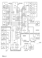
- the meter contains the first circuit part the actual control that comes with a Input / output module 4 and in particular with one second circuit part, the invention Interface circuit internal to the franking machine connected, which is advantageously as ASIC 14 can be trained.
- the control includes in known way a clock / date block 8, one Character store 9, a cost center store 10, a non-volatile memory 5, program memory 11 and memory 7, which with a Microprocessor in communicative connection.
- the input / output module 4 provides, for example via an RS 232 interface Connection to the modem 23 and possibly to the scale 22. The latter can be part of the base. Moreover are the display controller 3 and the module 4 Keyboard 2 connected.
- the input data is stored in the non-volatile memory (NVM) 5 saved so that the last setting received before the franking machine was switched off remains.
- the operating program is in the program memory 11 and fixed dates, for example for a Advertising slogan, saved.
- the cost center memory 10 the current accounting data Depending on the cost center, non-volatile before each print saved.
- the corresponding is in the character memory 9 Character set available. According to the inputs corresponding characters as pixel data in the Pixel memory 7 saved.
- the microprocessor is used as a control unit 6 for the entire franking machine and is connected to blocks 4, 5, 7 to 11 of the first circuit part 1 via address lines A and data lines D and via address, data and control lines (A, D, S) connected to the second circuit part 14, which is designed as an ASIC.
- the above-mentioned blocks are addressed by the microprocessor in accordance with the memory control signals S s generated in the decoder of the ASIC.
- the function-determining ones - in FIG. 1 shown - blocks of the first circuit part partial or total to at least one physical Component are summarized and others Measures should be taken to prevent tampering difficult by unauthorized persons.
- the Function of these blocks and such measures are for example in the German patent application DE 43 44 476 A1 explained in more detail.
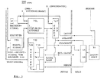
- the circuit part 14, shown in more detail in FIG. 2, for the interface inside the postage meter machine, which is designed in accordance with the type of postage meter machine, has a decoder 300 for providing the memory control signals, an actuator / sensor controller 400, an interrupt controller 600 and a print data controller 700.
- the address lines A0 to A3 and data lines D and control lines S are connected to all blocks 300, 400, 600 and 700. Address lines A13 to A19 are also present on the decoder.
- Decoder 300 provides memory control signals S s for blocks 400, 600 and 700.
- the block 400 for the actuator / sensor control outputs a signal I i on the output side to the block 600 for the interrupt control.
- the block 600 is connected on the output side to the control unit 6 via the lines for the data and control signals I o (FIG. 1).
- the ASIC circuit part 14 is equipped with an input s for connection to the sensors of the base and with an output a for connection to the actuators of the base of the franking machine via a register unit 28 (FIG. 1). More detailed information on the actuators / sensors and on the interrupt control can be found in EP 716 398 A2.
- the register groups of all blocks 300, 400, 600 and 700 can - in a manner not shown - within of the ASIC 14 form its own block 500, which in communication with the other blocks stands.
- a sensor for time-critical data is the encoder 13. On the one hand, this is - in the manner shown in FIG. 1 - directly at the input e of the control unit 6 and on the other hand is connected to the input e of the second circuit part (ASIC) 14.
- the encoder acts on a DMA controller present in the control unit 6.
- the DMA controller reads out a complete stamp image from the pixel memory (RAM) 7 and reads it into the print register (DR) of the print head 16 in print column-wise fashion via the ASIC print data controller 700.
- the encoder 13 acts directly on the print data controller 700 by supplying an external trigger signal for the transfer of the print data for the individual print columns to a second state machine 701.
- the print data controller 700 is in FIG a first variant explained.
- a third State machine 701 is with a transmit shift register 710 and with a test shift register 720 connected to the control of data transfer by means of a signal CLOCKOUT.
- the Send shift register 710 sends that from the DMA controller delivered bytes to the print register (DR) 15.
- a series-parallel conversion takes place here the data for the printhead electronics of the printhead 16.
- the printhead 16 contains for temporary storage the parallel print data register, which with a signal LATCH corresponding to the Encoder signal at input e can be controlled, as well Driver, which is signaled by a STROBE signal from the Control unit 6 can be controlled.
- the drivers control the actual printing elements of the Printhead 16.
- the ASIC 14 can be used in conjunction with the first Circuit part 1 based on a test circuit 702 serial data transfer can be monitored.
- the Test shift register 720 can get data from the print register 15 received serially, which after serial-parallel conversion from the control device 6 can be read via the data line D if necessary can.
- the ASIC 14 can be used in conjunction with the first circuit part 1 due to a local Loop and by means of the test circuit 702 serial data transfer can be tested. Is to provided that the bits of the Send shift register 710 for serial print data Purpose testing via a local loop LOCAL LOOP and into a test shift register by means of a test circuit 702 720 can be read.
- Additional registers can be in register block 500 of the ASIC's 14 can be provided and can be connected with the third state machine 701 more Data, clock or control signals to the printer register 15 and deliver the printhead electronics, see above that the control even when using different Printheads becomes possible.
- FIG. 4 is a block diagram for a second variant of the print data control according to the invention with training as a security module shown.
- the on an expanded printhead hardware connected print data control unit 700 - According to the embodiment shown in Figure 3 expanded to include a second code generator 703, a multiplexer 709, a demultiplexer 725 and a second comparator 723.
- the modification of the extended printhead hardware compared to the print data control unit shown in FIG on the one hand results from a very large number of print data to be transmitted, for example 200 dpi (dot per inch) for one Pressure column.
- Send shift register 710 or the print register DR 15 need to transfer data for a print column be designed. The printing is done column by column preferably on an envelope if the print column data parallel to the printhead STROBE signal is switched to the printhead.
- the predetermined Code via first switch means 34 den Pressure register 15 supplied, which the predetermined Code as activation code serial to the print data control unit 700 transmitted.
- the first switch 34 are preferably field effect transistors or other comparable taxable electronic switches.
- such a version has a Print data controller 700 a third state machine 701 on the input side with a Mode register group 750 for setting the Operating mode and output side with control inputs the transmit shift register 710, a test circuit 702 and the external print register 15 is to be switched on from a first Code generator 32 issued receipt code under Controlled by the third state machine 701 into a test shift register 720.
- the Test shift register 720 is the acknowledgment code can be called up in parallel and the test circuit 702 is according to a set security printer mode trained the serial data transfer between print register 15, print head electronics 30 on the one hand and the transmit shift register 710 on the other hand, to monitor the bits received to monitor for predetermined changes in state.
- an interrupt for Control unit 6 are transmitted to subsequently a print data transfer to the print head trigger.
- the control unit 6 runs automatically without Participation of the control unit 6 (CPU). Thereby the control unit 6 (CPU) is relieved.
- the interface circuit inside the franking machine is equipped with send and receive registers for the storage of data transmitted in parallel Data and with a shift register for that Series / parallel or parallel / series conversion of the from or to the print head via a print register transferred data.
- Print data length information becomes the print head as part of a coded data exchange, the u.a. the length of the print Image in bytes or in a predetermined number contains to pressure columns, transmitted.
- the u.a. the length of the print Image in bytes or in a predetermined number contains to pressure columns, transmitted.
- the aforementioned print data length information from the demultiplexer DEMUX 35 into the monitoring module 36 transmitted for print data length monitoring, before that sent to the printhead
- Print data transmission signal the unencrypted Contains image data.
- the state of activation is a print data length monitoring for the unencrypted image data performed to the Termination of data transmission for the aforementioned to determine the individual print image. Locking the Printhead will be reached when the predetermined print data length information Print data length triggered.
- a method for manipulation-proof print data control after another version works with several generated codes at the same time. It is provided that to carry out the encoded Data exchange code independently of each other are generated to compare the Printhead electronics transmitted codes with a generated first code and a comparison of the codes transmitted to the print data control unit a second code.
- the aforementioned has another version for such a print data controller 700 with training a second code generator for the security module 703 for generating one for everyone Imprint unique unlock codes and one third state machine 701 on the input side with a mode register group 750 for Setting the operating mode and on the output side with Control inputs of the transmit shift register 710, a test circuit 702 and the external print register 15 is connected to one of one emitted first connectable code generator 32 second receipt code under the control of the third state machine 701 into a test shift register 720 to insert.
- the second acknowledgment code is available in parallel before and the test circuit 702 is corresponding a set security printer mode, serial data transfer between print registers 15, printhead electronics 30 on the one hand and the transmit shift register 710, on the other hand, around the received bits to predetermined ones Monitor changes in state. Thus, if necessary an interrupt is transmitted to the control unit 6 in order to subsequently transfer a print data trigger to the printhead. If the Transmission over the DMA channel is started, this runs automatically without the involvement of the control unit 6 (CPU) onwards. This also makes the Control unit 6 (CPU) relieved.
- the print data control unit 700 which the Control unit 6 of pressure monitoring tasks relieve, it is provided that at the parallel Output of test shift register 720 a first Input and at the parallel output of a second Code generator 703 a second input of a digital comparator 723 for checking the second receipt codes is connected, the parallel data bits of the second acknowledgment code with those from the second code generator 703 supplied data bits of a first activation code be compared and if there is a mismatch Error message for the monitoring circuit (723, 600) is transmitted.
- the entrances are preferably of the digital comparator (723) with internal Buffer storage for temporary storage before a Check the code provided. Internally comes again an XOR link is used.
- the control unit CPU 6 is over a DMA channel connected to transmit shift register 710.
- the Transmission of the error message for interrupt control 600 interrupted and instead Agreement signals.
- To report the match becomes a signal J for interrupt control (600) transmitted.
- an interrupt is generated and delivered to the control unit CPU 6, whereby is caused by the control unit CPU 6 Print data to the transmit shift register via the DMA channel 710 are transmitted.
- a multiplexer MUX 709 connected to the second activation code or via the DMA channel transmitted print data in the send shift register Invite 710.
- the printhead electronics 30 has a fourth State machine 31 on the input side with a clock signal CLOCKOUT from the third state machine 701 and from a monitoring module 36 is supplied with an output signal and on the output side with a control input of a first one electronic switch 34, with a control input a second electronic switch 37, with a first code generator 32 and with a Control input of a demultiplexer DEMUX 35 connected is, at a first output of the Demultiplexers DEMUX 35 for parallel data transfer an internal buffer for the printhead DK 16 is connected.
- the parallel Output of the first code generator 32 a first Input and at the second output of the demultiplexer DEMUX 35 a second input of a digital Comparator 33 for checking the activation code is connected, the parallel retrievable data bits of the second activation code with those supplied by the first code generator 32 Data bits of a first acknowledgment code compared an error message if they do not match is transmitted to the monitoring module 36, that the monitoring module 36 otherwise at Agreement is unlocked and that from fourth state machine 31 of the demultiplexer DEMUX 35 for parallel data transmission via its first output to an internal buffer of the monitoring module 36 switched becomes.
- the monitoring module DLC 36 preferably has Counters to act on columns or bytes to carry out a pressure length monitoring.
- the counter DLC 36 generates an output signal to the fourth state machine 31 upon reaching one predetermined print length.
- the fourth state machine 31 acts on the Control input of the second electronic switch 37 to when a predetermined printing length is reached a signal supplied by encoder 13 LATCH from internal buffer of the print head DK 16 switch off, so that no further print data can be printed by the print head DK.
- the fourth State machine 31 the control input of the first electronic switch 34 applied and from first code generator 32 into the print register second receipt code is read, which for Print data control 700 is transmitted.
- the inputs of the digital comparator 33 with internal buffer storage for temporary storage before checking the code.
- this franking machine internal interface circuit to the base a number of serial Interfaces with any expansion options forms, this enables an adaptation to the various franking systems and to each base Franking machine, on the one hand for the purpose of sensor query and for actuator setting, with a non-periodic Query by a microprocessor 6 and with an interrupt controller 600 and on the other hand for a print data controller 700 with operating mode setting and testing options.
- the invention is not based on the present embodiment limited. Rather is a number of variants conceivable, which of the shown Solution also with different types Make use.
Landscapes
- Physics & Mathematics (AREA)
- General Physics & Mathematics (AREA)
- Engineering & Computer Science (AREA)
- Computer Hardware Design (AREA)
- General Engineering & Computer Science (AREA)
- Devices For Checking Fares Or Tickets At Control Points (AREA)
- Accessory Devices And Overall Control Thereof (AREA)
- Arrangements For Transmission Of Measured Signals (AREA)
Applications Claiming Priority (3)
| Application Number | Priority Date | Filing Date | Title |
|---|---|---|---|
| DE4445053 | 1994-12-07 | ||
| DE4445053A DE4445053C2 (de) | 1994-12-07 | 1994-12-07 | Frankiermaschineninterne Schnittstellenschaltung |
| EP95250302A EP0716398B1 (fr) | 1994-12-07 | 1995-12-07 | Circuit d'interface pour machine d'affranchissement |
Related Parent Applications (2)
| Application Number | Title | Priority Date | Filing Date |
|---|---|---|---|
| EP95250302.7 Division | 1995-12-07 | ||
| EP95250302A Division EP0716398B1 (fr) | 1994-12-07 | 1995-12-07 | Circuit d'interface pour machine d'affranchissement |
Publications (3)
| Publication Number | Publication Date |
|---|---|
| EP1154382A2 true EP1154382A2 (fr) | 2001-11-14 |
| EP1154382A3 EP1154382A3 (fr) | 2002-02-06 |
| EP1154382B1 EP1154382B1 (fr) | 2006-08-16 |
Family
ID=6536108
Family Applications (2)
| Application Number | Title | Priority Date | Filing Date |
|---|---|---|---|
| EP01250293A Expired - Lifetime EP1154382B1 (fr) | 1994-12-07 | 1995-12-07 | Procédé de commande protégé contre la manipulation des données d'impression et circuit d'interface interne pour machines d'affranchissement |
| EP95250302A Expired - Lifetime EP0716398B1 (fr) | 1994-12-07 | 1995-12-07 | Circuit d'interface pour machine d'affranchissement |
Family Applications After (1)
| Application Number | Title | Priority Date | Filing Date |
|---|---|---|---|
| EP95250302A Expired - Lifetime EP0716398B1 (fr) | 1994-12-07 | 1995-12-07 | Circuit d'interface pour machine d'affranchissement |
Country Status (3)
| Country | Link |
|---|---|
| US (1) | US5710721A (fr) |
| EP (2) | EP1154382B1 (fr) |
| DE (3) | DE4445053C2 (fr) |
Cited By (4)
| Publication number | Priority date | Publication date | Assignee | Title |
|---|---|---|---|---|
| EP1361487A3 (fr) * | 2002-05-10 | 2004-01-28 | Seiko Epson Corporation | Dispositif et procédé de commande de moteurs |
| US6733194B2 (en) | 2002-07-04 | 2004-05-11 | Francotyp-Postalia Ag & Co. Kg | Arrangement for controlling printing in a mail-processing device |
| DE10250820A1 (de) * | 2002-10-31 | 2004-05-13 | Francotyp-Postalia Ag & Co. Kg | Anordnung zum Drucken eines Druckbildes mit Bereichen unterschiedlicher Druckbildauflösung |
| US6739245B2 (en) | 2002-07-04 | 2004-05-25 | Francotyp-Postalia Ag & Co. Kg | Method for controlling printing in a mail-processing device |
Families Citing this family (21)
| Publication number | Priority date | Publication date | Assignee | Title |
|---|---|---|---|---|
| DE4445053C2 (de) | 1994-12-07 | 2003-04-10 | Francotyp Postalia Ag | Frankiermaschineninterne Schnittstellenschaltung |
| US5983291A (en) * | 1996-09-24 | 1999-11-09 | Cirrus Logic, Inc. | System for storing each of streams of data bits corresponding from a separator thereby allowing an input port accommodating plurality of data frame sub-functions concurrently |
| DE19711998A1 (de) * | 1997-03-13 | 1998-09-17 | Francotyp Postalia Gmbh | Postverarbeitungssystem mit einer über Personalcomputer gesteuerten druckenden Maschinen-Basisstation |
| US5877798A (en) * | 1997-03-21 | 1999-03-02 | Lexmark International Inc. | Method and apparatus for automatically determining the style printhead installed in a laser printer |
| US6493597B1 (en) * | 1998-01-30 | 2002-12-10 | Inspectron | Print monitoring system and method using slave signal processor/master processor arrangement |
| DE19843252A1 (de) | 1998-09-11 | 2000-03-16 | Francotyp Postalia Gmbh | Verfahren zur Dateneingabe in einen Portorechner und Anordnung zur Durchführung des Verfahrens |
| DE19925381A1 (de) * | 1999-06-02 | 2000-12-07 | Francotyp Postalia Gmbh | Anordnung zum Tariftabellenladen |
| DE19928058B4 (de) | 1999-06-15 | 2005-10-20 | Francotyp Postalia Ag | Anordnung und Verfahren zur Generierung eines Sicherheitsabdruckes |
| DE19958949A1 (de) | 1999-11-26 | 2001-06-07 | Francotyp Postalia Gmbh | Verfahren zum automatischen Bestellen von Verbrauchsmaterial und Anordnung zur Durchführung des Verfahrens |
| DE19958941B4 (de) | 1999-11-26 | 2006-11-09 | Francotyp-Postalia Gmbh | Verfahren zum Schutz eines Gerätes vor einem Betreiben mit unzulässigem Verbrauchsmaterial |
| DE19958946B4 (de) * | 1999-11-26 | 2006-11-09 | Francotyp-Postalia Gmbh | Verfahren zum Piraterieschutz eines Gerätes |
| DE19958948B4 (de) * | 1999-11-26 | 2005-06-02 | Francotyp-Postalia Ag & Co. Kg | Verfahren zur Bestimmung der Anzahl von mit einer Tintenrestmenge ausführbaren Drucken und Vorrichtung zur Durchführung des Verfahrens |
| DE20008548U1 (de) | 2000-05-08 | 2000-08-03 | Francotyp-Postalia AG & Co., 16547 Birkenwerder | Anordnung zur Erkennung der Schaltstellung eines Netzschalters |
| DE10036345B4 (de) * | 2000-07-26 | 2005-07-07 | Francotyp-Postalia Ag & Co. Kg | Anordnung und Verfahren zur Datennachführung für Aufwärmzyklen von Tintenstrahldruckköpfen |
| US6953234B2 (en) * | 2003-07-07 | 2005-10-11 | Francotyp-Postalia Ag & Co. Kg | Method and arrangement for reducing printer errors during printing in a mail processing device |
| DE202004015279U1 (de) * | 2004-10-01 | 2005-01-13 | Francotyp-Postalia Ag & Co. Kg | Anordnung für ein druckendes Postverarbeitungsgerät |
| DE102005041455A1 (de) * | 2005-08-31 | 2007-03-15 | Abb Patent Gmbh | Automatisierungstechnische Einrichtung |
| DE102005043485A1 (de) | 2005-09-13 | 2007-03-15 | Abb Patent Gmbh | Automatisierungstechnische Einrichtung |
| DE102005043482A1 (de) * | 2005-09-13 | 2007-03-15 | Abb Patent Gmbh | Automatisierungstechnische Einrichtung |
| DE102005043481A1 (de) * | 2005-09-13 | 2007-03-15 | Abb Patent Gmbh | Automatisierungstechnische Einrichtung |
| US8582969B1 (en) * | 2010-11-30 | 2013-11-12 | Adtran, Inc. | Passive optical network (PON) having optical network unit (ONU) using feedback to detect rogue conditions and related method |
Citations (8)
| Publication number | Priority date | Publication date | Assignee | Title |
|---|---|---|---|---|
| EP0231452A2 (fr) | 1982-01-29 | 1987-08-12 | Pitney Bowes Inc. | Systèmes à microprocesseur pour dispositif d'affranchissement électronique |
| US4746234A (en) | 1983-07-23 | 1988-05-24 | Francotyp-Postalia Gmbh | Relating to postal franking machines |
| DE3833746A1 (de) | 1988-09-30 | 1990-04-05 | Siemens Ag | Thermodruckverfahren mit vorheizung |
| EP0465236A2 (fr) | 1990-07-04 | 1992-01-08 | Neopost Limited | Machine d'affranchissement |
| US5199105A (en) | 1988-09-14 | 1993-03-30 | National Semiconductor Corporation | Universal asynchronous receiver/transmitter |
| US5267172A (en) | 1990-07-04 | 1993-11-30 | Alcatel Satmam | Mail franking machine including an interface application specific integrated circuit |
| DE4344476A1 (de) | 1993-12-21 | 1995-06-22 | Francotyp Postalia Gmbh | Verfahren zur Verbesserung der Sicherheit von Frankiermaschinen |
| EP0716398A2 (fr) | 1994-12-07 | 1996-06-12 | Francotyp-Postalia GmbH | Circuit d'interface pour machine d'affranchissement et procédé de commande protégé contre la manipulation des données d'impression |
Family Cites Families (7)
| Publication number | Priority date | Publication date | Assignee | Title |
|---|---|---|---|---|
| GB2052813B (en) * | 1979-05-31 | 1983-03-09 | Micronology Ltd | Interface unit between a computer and a hardcopy output device |
| US4916623A (en) * | 1982-01-29 | 1990-04-10 | Pitney Bowes Inc. | Electronic postage meter having redundant memory |
| US4866421A (en) * | 1987-06-18 | 1989-09-12 | Texas Instruments Incorporated | Communications circuit having an interface for external address decoding |
| CA2049407A1 (fr) * | 1990-08-20 | 1992-02-21 | Wu Sheng-Jung | Dispositif de traitement automatique du courrier a gamme de fonctions complete |
| GB2256396B (en) * | 1991-05-29 | 1995-03-29 | Alcatel Business Systems | Method of remote diagnostics for franking machines |
| US5455700A (en) * | 1992-04-30 | 1995-10-03 | Fisher Controls International, Inc. | Regenerative communication channel extender |
| DE4224955C2 (de) * | 1992-07-24 | 1998-11-26 | Francotyp Postalia Gmbh | Anordnung und Verfahren für einen internen Kostenstellendruck |
-
1994
- 1994-12-07 DE DE4445053A patent/DE4445053C2/de not_active Expired - Fee Related
-
1995
- 1995-12-06 US US08/568,019 patent/US5710721A/en not_active Expired - Lifetime
- 1995-12-07 DE DE59511062T patent/DE59511062D1/de not_active Expired - Lifetime
- 1995-12-07 EP EP01250293A patent/EP1154382B1/fr not_active Expired - Lifetime
- 1995-12-07 EP EP95250302A patent/EP0716398B1/fr not_active Expired - Lifetime
- 1995-12-07 DE DE59510090T patent/DE59510090D1/de not_active Expired - Lifetime
Patent Citations (8)
| Publication number | Priority date | Publication date | Assignee | Title |
|---|---|---|---|---|
| EP0231452A2 (fr) | 1982-01-29 | 1987-08-12 | Pitney Bowes Inc. | Systèmes à microprocesseur pour dispositif d'affranchissement électronique |
| US4746234A (en) | 1983-07-23 | 1988-05-24 | Francotyp-Postalia Gmbh | Relating to postal franking machines |
| US5199105A (en) | 1988-09-14 | 1993-03-30 | National Semiconductor Corporation | Universal asynchronous receiver/transmitter |
| DE3833746A1 (de) | 1988-09-30 | 1990-04-05 | Siemens Ag | Thermodruckverfahren mit vorheizung |
| EP0465236A2 (fr) | 1990-07-04 | 1992-01-08 | Neopost Limited | Machine d'affranchissement |
| US5267172A (en) | 1990-07-04 | 1993-11-30 | Alcatel Satmam | Mail franking machine including an interface application specific integrated circuit |
| DE4344476A1 (de) | 1993-12-21 | 1995-06-22 | Francotyp Postalia Gmbh | Verfahren zur Verbesserung der Sicherheit von Frankiermaschinen |
| EP0716398A2 (fr) | 1994-12-07 | 1996-06-12 | Francotyp-Postalia GmbH | Circuit d'interface pour machine d'affranchissement et procédé de commande protégé contre la manipulation des données d'impression |
Cited By (6)
| Publication number | Priority date | Publication date | Assignee | Title |
|---|---|---|---|---|
| EP1361487A3 (fr) * | 2002-05-10 | 2004-01-28 | Seiko Epson Corporation | Dispositif et procédé de commande de moteurs |
| US6847180B2 (en) | 2002-05-10 | 2005-01-25 | Seiko Epson Corporation | Motor control apparatus and motor control method |
| US6733194B2 (en) | 2002-07-04 | 2004-05-11 | Francotyp-Postalia Ag & Co. Kg | Arrangement for controlling printing in a mail-processing device |
| US6739245B2 (en) | 2002-07-04 | 2004-05-25 | Francotyp-Postalia Ag & Co. Kg | Method for controlling printing in a mail-processing device |
| DE10250820A1 (de) * | 2002-10-31 | 2004-05-13 | Francotyp-Postalia Ag & Co. Kg | Anordnung zum Drucken eines Druckbildes mit Bereichen unterschiedlicher Druckbildauflösung |
| US6776544B2 (en) | 2002-10-31 | 2004-08-17 | Francotyp-Postalia Ag & Co. Kg | Arrangement for printing a print image having regions with different print image resolution |
Also Published As
| Publication number | Publication date |
|---|---|
| EP1154382A3 (fr) | 2002-02-06 |
| EP0716398A3 (fr) | 1998-07-08 |
| EP0716398B1 (fr) | 2002-03-06 |
| EP0716398A2 (fr) | 1996-06-12 |
| DE59510090D1 (de) | 2002-04-11 |
| US5710721A (en) | 1998-01-20 |
| DE4445053A1 (de) | 1996-06-13 |
| DE59511062D1 (de) | 2006-09-28 |
| EP1154382B1 (fr) | 2006-08-16 |
| DE4445053C2 (de) | 2003-04-10 |
Similar Documents
| Publication | Publication Date | Title |
|---|---|---|
| EP1154382B1 (fr) | Procédé de commande protégé contre la manipulation des données d'impression et circuit d'interface interne pour machines d'affranchissement | |
| DE69016247T2 (de) | Frankiermaschine. | |
| EP1696390B1 (fr) | Procédé et dispositif de controller l'impression d'une imprimante à transfert thermique | |
| DE68924631T2 (de) | Vorrichtung zum Aufbringen von Zeichen gemäss einer verschlüsselten Botschaft. | |
| DE10011192A1 (de) | Frankiermaschine mit abgesichertem Druckkopf | |
| EP0921008B1 (fr) | Procédé compensateur de tolérance dans une tête d'impression à jet d'encre | |
| DE69527258T2 (de) | System zum Abrechnen von Postgebühren mit Mitteln zum Übertragen ASCII-kodierter variabler Informationen zum Steuern eines externen Druckers | |
| DE69532947T2 (de) | Frankiersystem mit zugeordneten und nichtzugeordneten Postgebührendruckeinrichtungen | |
| DE3729342A1 (de) | Sicherheitsdrucker fuer ein wertdrucksystem | |
| EP0440021B1 (fr) | Procédé d'identification de machines à affranchir et à tamponner | |
| EP1416430B1 (fr) | Dispositif pour imprimer des images ayant des zones d'impression à résolutions différentes | |
| DE69632518T2 (de) | Digitales Frankiermaschinensystem mit einer auswechselbaren Druckeinheit mit Systemsoftware-Aktualisierung | |
| DE69729915T2 (de) | Verfahren und Vorrichtung zur ferngesteuerten Änderung von Sicherheitsmerkmalen einer Frankiermaschine | |
| EP3588450B1 (fr) | Procédé et système de commande de l'utilisation d'une unité de cartouche | |
| DE3613025C2 (de) | Nichtgesichertes Portogebühren-Aufbringungssystem | |
| DE4224955A1 (de) | Verfahren und Anordnung für einen internen Kostenstellendruck | |
| EP1378820B1 (fr) | Système de contrôle d'imprimante dans un système de traitement de courrier | |
| EP1829692A2 (fr) | Procédé destiné à l'amélioration de la qualité de l'impression à l'aide d'une tête d'imprimante à transfert thermique et agencement destiné à l'exécution du procédé | |
| EP1387245B1 (fr) | Méthode de contrôle d'une imprimante dans un système de traitement de courrier | |
| EP1132868A1 (fr) | Machine à affranchir avec une tête d'impression sécurisé | |
| EP1154381A1 (fr) | Machine à affranchir et procédé de déverrouillage d'une machine à affranchir | |
| DE19928058A1 (de) | Anordnung und Verfahren zur Generierung eines Sicherheitsabdruckes | |
| DE69123340T2 (de) | Frankiermaschine | |
| DE102004032323A1 (de) | Verfahren und Anordnung zum Erstatten von Porto | |
| EP1602495B1 (fr) | Apppareil et méthode pour controller une tête d'impression à transfer thermique |
Legal Events
| Date | Code | Title | Description |
|---|---|---|---|
| PUAI | Public reference made under article 153(3) epc to a published international application that has entered the european phase |
Free format text: ORIGINAL CODE: 0009012 |
|
| AC | Divisional application: reference to earlier application |
Ref document number: 716398 Country of ref document: EP |
|
| AK | Designated contracting states |
Kind code of ref document: A2 Designated state(s): CH DE FR GB IT LI |
|
| PUAL | Search report despatched |
Free format text: ORIGINAL CODE: 0009013 |
|
| AK | Designated contracting states |
Kind code of ref document: A3 Designated state(s): CH DE FR GB IT LI |
|
| 17P | Request for examination filed |
Effective date: 20020607 |
|
| AKX | Designation fees paid |
Free format text: CH DE FR GB IT LI |
|
| 17Q | First examination report despatched |
Effective date: 20030915 |
|
| RAP1 | Party data changed (applicant data changed or rights of an application transferred) |
Owner name: FRANCOTYP-POSTALIA GMBH |
|
| GRAJ | Information related to disapproval of communication of intention to grant by the applicant or resumption of examination proceedings by the epo deleted |
Free format text: ORIGINAL CODE: EPIDOSDIGR1 |
|
| GRAP | Despatch of communication of intention to grant a patent |
Free format text: ORIGINAL CODE: EPIDOSNIGR1 |
|
| GRAP | Despatch of communication of intention to grant a patent |
Free format text: ORIGINAL CODE: EPIDOSNIGR1 |
|
| GRAS | Grant fee paid |
Free format text: ORIGINAL CODE: EPIDOSNIGR3 |
|
| GRAA | (expected) grant |
Free format text: ORIGINAL CODE: 0009210 |
|
| AC | Divisional application: reference to earlier application |
Ref document number: 0716398 Country of ref document: EP Kind code of ref document: P |
|
| AK | Designated contracting states |
Kind code of ref document: B1 Designated state(s): CH DE FR GB IT LI |
|
| REG | Reference to a national code |
Ref country code: GB Ref legal event code: FG4D Free format text: NOT ENGLISH |
|
| REG | Reference to a national code |
Ref country code: CH Ref legal event code: EP |
|
| REF | Corresponds to: |
Ref document number: 59511062 Country of ref document: DE Date of ref document: 20060928 Kind code of ref document: P |
|
| GBT | Gb: translation of ep patent filed (gb section 77(6)(a)/1977) |
Effective date: 20061004 |
|
| ET | Fr: translation filed | ||
| PLBE | No opposition filed within time limit |
Free format text: ORIGINAL CODE: 0009261 |
|
| STAA | Information on the status of an ep patent application or granted ep patent |
Free format text: STATUS: NO OPPOSITION FILED WITHIN TIME LIMIT |
|
| 26N | No opposition filed |
Effective date: 20070518 |
|
| PGFP | Annual fee paid to national office [announced via postgrant information from national office to epo] |
Ref country code: CH Payment date: 20091224 Year of fee payment: 15 |
|
| PGFP | Annual fee paid to national office [announced via postgrant information from national office to epo] |
Ref country code: IT Payment date: 20091218 Year of fee payment: 15 Ref country code: GB Payment date: 20091218 Year of fee payment: 15 Ref country code: FR Payment date: 20100108 Year of fee payment: 15 |
|
| PGFP | Annual fee paid to national office [announced via postgrant information from national office to epo] |
Ref country code: DE Payment date: 20091013 Year of fee payment: 15 |
|
| REG | Reference to a national code |
Ref country code: CH Ref legal event code: PL |
|
| GBPC | Gb: european patent ceased through non-payment of renewal fee |
Effective date: 20101207 |
|
| REG | Reference to a national code |
Ref country code: FR Ref legal event code: ST Effective date: 20110831 |
|
| PG25 | Lapsed in a contracting state [announced via postgrant information from national office to epo] |
Ref country code: FR Free format text: LAPSE BECAUSE OF NON-PAYMENT OF DUE FEES Effective date: 20110103 Ref country code: CH Free format text: LAPSE BECAUSE OF NON-PAYMENT OF DUE FEES Effective date: 20101231 Ref country code: LI Free format text: LAPSE BECAUSE OF NON-PAYMENT OF DUE FEES Effective date: 20101231 |
|
| REG | Reference to a national code |
Ref country code: DE Ref legal event code: R119 Ref document number: 59511062 Country of ref document: DE Effective date: 20110701 |
|
| PG25 | Lapsed in a contracting state [announced via postgrant information from national office to epo] |
Ref country code: DE Free format text: LAPSE BECAUSE OF NON-PAYMENT OF DUE FEES Effective date: 20110701 Ref country code: GB Free format text: LAPSE BECAUSE OF NON-PAYMENT OF DUE FEES Effective date: 20101207 |
|
| PG25 | Lapsed in a contracting state [announced via postgrant information from national office to epo] |
Ref country code: IT Free format text: LAPSE BECAUSE OF NON-PAYMENT OF DUE FEES Effective date: 20101207 |