EP1154520A1 - Connecteur électrique et procédé pour le sertissage sur des fils électriques - Google Patents
Connecteur électrique et procédé pour le sertissage sur des fils électriques Download PDFInfo
- Publication number
- EP1154520A1 EP1154520A1 EP01304119A EP01304119A EP1154520A1 EP 1154520 A1 EP1154520 A1 EP 1154520A1 EP 01304119 A EP01304119 A EP 01304119A EP 01304119 A EP01304119 A EP 01304119A EP 1154520 A1 EP1154520 A1 EP 1154520A1
- Authority
- EP
- European Patent Office
- Prior art keywords
- press
- engaging arms
- electrical
- contact
- electrical wire
- Prior art date
- Legal status (The legal status is an assumption and is not a legal conclusion. Google has not performed a legal analysis and makes no representation as to the accuracy of the status listed.)
- Granted
Links
- 238000000034 method Methods 0.000 title claims description 6
- 238000009413 insulation Methods 0.000 claims abstract description 45
- 239000012212 insulator Substances 0.000 claims description 39
- 239000004020 conductor Substances 0.000 claims description 14
- 230000000295 complement effect Effects 0.000 claims description 9
- 238000002788 crimping Methods 0.000 description 10
- 238000005452 bending Methods 0.000 description 3
- 230000014759 maintenance of location Effects 0.000 description 2
- 230000015572 biosynthetic process Effects 0.000 description 1
- 230000006835 compression Effects 0.000 description 1
- 238000007906 compression Methods 0.000 description 1
- 230000000694 effects Effects 0.000 description 1
- 238000003780 insertion Methods 0.000 description 1
- 230000037431 insertion Effects 0.000 description 1
- 230000013011 mating Effects 0.000 description 1
- 239000002184 metal Substances 0.000 description 1
- 230000002093 peripheral effect Effects 0.000 description 1
- 229920001296 polysiloxane Polymers 0.000 description 1
- 230000007704 transition Effects 0.000 description 1
Images


Classifications
-
- H—ELECTRICITY
- H01—ELECTRIC ELEMENTS
- H01R—ELECTRICALLY-CONDUCTIVE CONNECTIONS; STRUCTURAL ASSOCIATIONS OF A PLURALITY OF MUTUALLY-INSULATED ELECTRICAL CONNECTING ELEMENTS; COUPLING DEVICES; CURRENT COLLECTORS
- H01R4/00—Electrically-conductive connections between two or more conductive members in direct contact, i.e. touching one another; Means for effecting or maintaining such contact; Electrically-conductive connections having two or more spaced connecting locations for conductors and using contact members penetrating insulation
- H01R4/10—Electrically-conductive connections between two or more conductive members in direct contact, i.e. touching one another; Means for effecting or maintaining such contact; Electrically-conductive connections having two or more spaced connecting locations for conductors and using contact members penetrating insulation effected solely by twisting, wrapping, bending, crimping, or other permanent deformation
- H01R4/18—Electrically-conductive connections between two or more conductive members in direct contact, i.e. touching one another; Means for effecting or maintaining such contact; Electrically-conductive connections having two or more spaced connecting locations for conductors and using contact members penetrating insulation effected solely by twisting, wrapping, bending, crimping, or other permanent deformation by crimping
- H01R4/183—Electrically-conductive connections between two or more conductive members in direct contact, i.e. touching one another; Means for effecting or maintaining such contact; Electrically-conductive connections having two or more spaced connecting locations for conductors and using contact members penetrating insulation effected solely by twisting, wrapping, bending, crimping, or other permanent deformation by crimping for cylindrical elongated bodies, e.g. cables having circular cross-section
- H01R4/184—Electrically-conductive connections between two or more conductive members in direct contact, i.e. touching one another; Means for effecting or maintaining such contact; Electrically-conductive connections having two or more spaced connecting locations for conductors and using contact members penetrating insulation effected solely by twisting, wrapping, bending, crimping, or other permanent deformation by crimping for cylindrical elongated bodies, e.g. cables having circular cross-section comprising a U-shaped wire-receiving portion
- H01R4/185—Electrically-conductive connections between two or more conductive members in direct contact, i.e. touching one another; Means for effecting or maintaining such contact; Electrically-conductive connections having two or more spaced connecting locations for conductors and using contact members penetrating insulation effected solely by twisting, wrapping, bending, crimping, or other permanent deformation by crimping for cylindrical elongated bodies, e.g. cables having circular cross-section comprising a U-shaped wire-receiving portion combined with a U-shaped insulation-receiving portion
Definitions
- the present invention relates to an electrical contact and a method for press-bonding the electrical contact to an electrical wire.
- This electrical contact 100 has a contact part 102 which electrically contacts a mating electrical contact (not shown) and a wire retention part 104 which is connected by bending the barrel around the outer circumference of an electrical wire (not shown).
- the wire retention part 104 is constructed from a pair of conductor barrels 104a which are bent about the core of the wire and frictionally engage the core wire, i.e., the conductor of the electrical wire.
- a pair of insulator barrels 104b are also provided and are bent about the outer covering of the wire and frictionally engage the outer covering, i.e., the insulation of the electrical wire.
- the conductor barrels 104a are formed so that their positions are offset relative to each other in the axial direction of the electrical contact 100.
- the insulator barrels 104b are also formed so that their positions are offset relative to each other in the axial direction of the electrical contact 100.
- the barrels are bent or press-bonded so that they envelop and frictionally engage the electrical wire from both sides of the electrical wire, thus pressing and fastening the outer covering of the electrical wire in place with the broadest possible area.
- the barrel parts 104bof the electrical contact 100 disclosed in the above-mentioned Japanese Utility Model Application Kokoku No. S45-33001 are separated from each other in the axial direction of the electrical contact 100 after the barrels have been bent. Accordingly, these barrel parts 104b, 104b are wrapped around the circumference of the outer covering of the electrical wire without contacting each other. As a result, the electrical contact 100 can be used on wires of various diameters, and the total length of the electrical contact 100 can be made relatively short.
- the pair of barrel parts 104b have no structural integrity following bending or press-bonding and consequently, the barrel parts 104b tend to open, so that the frictional engagement with the wire is weak, thereby allowing the wire to be inadvertently removed causing electrical failure.
- the present invention was devised to solve the above referenced problems. Consequently, the invention provides a compact electrical contact which has a high press-bonding strength while facilitating a broad range of applicable electrical wire diameters.
- the electrical contact of the present invention has an electrical contact part, a conductor barrel that is press-bonded to or in frictional engagement with the core wire of an electrical wire, and an insulator barrel that is press-bonded to or in frictional engagement with the insulating covering of the electrical wire.
- the insulator barrel is constructed from a pair of left and right press-bonding parts disposed in positions that are offset relative to each other in the axial direction of the electrical wire.
- the electrical contact is constructed so that when the press-bonding parts are press-bonded to the electrical wire, the facing edges of the press-bonding parts, which face each other in the axial direction, contact each other on the electrical wire.
- Both surfaces of the facing edges of the press-bonding parts may be subjected to swage working.
- the entire peripheries or circumferences of only the inside surfaces of the press-bonding parts may be subjected to swage working.
- the entire circumferences of the outside surfaces may be subjected to swage working in addition to the entire circumferences of the inside surfaces.
- both surfaces of the facing edges refers both to the inside surfaces of the facing edge parts of the plate members that form the press-bonding parts, i.e., the surfaces that contact the outer covering of the electrical wire when press-bonding is performed, and the outside surfaces of the facing edge parts, i.e., the surfaces that can be seen from the outside following press-bonding.
- the shapes of the tip end portions of the press-bonding parts and the shapes of the corresponding portions that face these tip end portions during the press-bonding of the press-bonding parts may be complementary shapes.
- the term "complementary'' also includes cases in which the shapes of only portions of the tip end portions and the shapes of the corresponding portions are shapes that are complementary to each other.
- the electrical wire press-bonding method using the electrical contact of the present invention is also described.
- the pair of press-bonding parts make sliding contact with each other at the facing edges of said press-bonding parts, so that the respective tip ends of the press-bonding parts move while describing portions of a spiral track along the outer circumference of the aforementioned electrical wire.
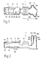
- the contact 1 is formed by stamping and bending a single metal plate.
- the contact main body 4 is substantially box-shaped and has a pin receiving section 6 in front and a wire termination section 8 in the rear.
- the wire termination section 8 has a conductor crimp section 10 and an insulator crimp section 11.
- the main body 4 has a set of side walls 13 that extend parallel to each other.
- the side walls 13 extend from the main body 4 to the pin receiving section 6.
- a bridge or partial top wall 16 is formed on the front end portion of a first respective side wall 13. The bridge extends from the respective side wall to the other side wall, such that the side walls 13 are bridged by this bridge 16.
- a connecting member 20 extends from the upper edge of the other side wall 13, and forms a bridge to the first respective side wall 13.
- a cut-out 24 is formed in the connecting member 20.
- a resilient contact section 30 extends from the connecting member 20 toward the interior of the pin receiving section 6 along the longitudinal axis of the contact 1.
- a lance 36, pushed out by means of a press mold (not shown) is formed as an integral part of a bottom wall 34 of the pin receiving section 6 opposite the resilient contact section 30.
- the conductor crimp section 10 which is formed as an integral part of the main body 4 at the rear of the main body 4, is fastened to a core wire or conductor 52 ( Figure 4) of wire 50 or to a core wire or conductor 62 ( Figure 5) of wire 60 by crimping or any other known means of terminating a conductor to a terminal.
- the insulator crimp section 11 is formed to the rear of the conductor crimp section 10.
- the insulator crimp section 11 has a pair of insulator engaging arms 12a, whose positions are offset relative to each other in the axial direction of the contact 1. These insulator engaging arms 12a, are fastened by crimping or press-bonding to the outer insulation covering 54 ( Figure 4) of the wire 50 or the insulation covering 64 ( Figure 5) of the wire 60.
- the outer peripheral or circumferential edges of the insulation engaging arms 12a,12b are swaged or work hardened to create beveled surfaces 18a,18b on the interior surface 15a,15b thereof.
- the surfaces 15a,15b engage the insulation covering 54 or 64.
- the outer circumferential edges of the insulation engaging arms 12a,12b are swaged or work hardened to create beveled surfaces 28a,28b on the outside surfaces 22a,22b of the insulation engaging arms 12a,12b.
- the outer covering 54 of the electrical wire 50 is press-bonded or crimped by the insulation engaging arms such that the outer covering 54 is captured from both sides by the insulation engaging arms 12a,12b.
- the core wire 52 is crimped and electrically connected by the conductor crimp section 10.
- the respective facing edges 38a,38b that are positioned facing each other in the axial direction, contact each other as shown in Figure 4 (B).
- the facing edges 38a,38b move in opposite directions as indicated by the arrows M and M' while making sliding contact with each other.
- the insulation engaging arms 12a,12b are tapered from the tip end portions 40a,40b to the fixed ends of the insulation engaging arms, the insulation engaging arms 12a,12b move in opposite directions in the axial direction of the electrical wire 50 while making sliding contact with each other.
- the tip end portions 40a, 40b describe portions of a spiral track along the outer circumference of the electrical wire 50.
- the insulator engaging arms 12a,12b are formed into an integral unit, and are fastened by crimping or press-bonding to the electrical wire 50.
- the tip end portions 40a and 40b of the respective press-bonding parts 12a and 12b do not reach the edges of corresponding portions (described later) of the contact 1, as is shown in Figures 4 (A) and 4 (C).
- the insulator engaging arms 12a and 12b are completely wrapped around the circumference of the electrical wire 60.
- the insulator engaging arms 12a and 12b are wrapped further around the outer circumference of the electrical wire 60 than the arms are in the case of the electrical wire 50. Accordingly, the range in which the facing edges 38a and 38b make sliding contact is greatly increased.
- the respective insulator engaging arms 12a and 12b are further displaced in opposite directions along the axial line of the electrical wire 60, so that the electrical wire 60 is firmly held in position.
- the tip end portion 40a of the insulator engaging arm 12a is positioned in the first corresponding portion 42 of the contact 1.
- This first corresponding portion 42 is located in a transition area between the insulator engaging arm 12b and the conductor crimp section 10 and has a curved shape that is complementary to the shape of the tip end portion 40a.
- the tip end portion 40a fits precisely into the first corresponding portion 42, so that movement of the tip end portion 40a into and away from the outer insulation cover 64.
- damage to the outer covering 64 of the electrical wire 60 that might be caused by the tip end portion 40a of the insulator engaging arm 12a moving inward and biting into the outer covering 64, as well as an increase in the external dimensions of the contact 1 that might be caused by the tip end portion 40a moving outward, can be prevented.
- the tip end portion 40a and first corresponding portion 42 make surface contact with the electrical wire 60 as an integral unit, so that strong press-bonding or crimping is accomplished.
- a second corresponding portion 44 that corresponds to the tip end portion 40b of the insulator engaging arm 12b is at the rear end of the contact 1.
- a part of the second corresponding portion 44 has a complementary shape to the conductor engaging arm 12b.
- a female-type contact is described in the embodiment; however, the invention can also be used in a male-type contact.
- the pair of insulator engaging arms are, which are disposed in positions that are offset relative to each other in the axial direction of the electrical wire, are crimped or press-bonded to the electrical wire, the facing edges of the insulator engaging arms contact each other and contact the electrical wire. Accordingly, the press-bonding strength can be increased by forming the pair of insulator engaging arms into a unit that has structural integrity while maintaining a broad range of applicable electrical wire diameters. Furthermore, since the facing insulator engaging arms are not separated by a gap in the axial direction of the electrical wire, the dimension of the electrical contact in the axial direction can be shortened, so that a compact connector can be obtained.
- each insulator engaging arm is subjected to swage working, the gaps formed in the swage-worked areas act as relief areas for the compressed insulation covering. This prevents the insulator engaging arms from biting into or damaging the insulation covering. This is especially effective in the case of electrical wires that are superior in terms of flexibility but easily damaged, e.g., electrical wires with an outer covering made of silicone, etc., that extend to the back side of the display screen in notebook-type personal computers.
- each insulator engaging arm is subjected to swage working, flash generated on the outside surface is eliminated. Accordingly, when the electrical contact is inserted into the cavity of a connector housing, there is no interference between the inside walls of the cavity and such flash, so that the insertion of the electrical contact can be smoothly accomplished.
- the shape of the tip end portions of the insulator engaging arms and the shape of the corresponding portions that are contacted by these tip end portions during the crimping or press-bonding of the insulation engaging arms are complementary in shape, then sliding contact between the insulation engaging arms can be smoothly accomplished.
- the tip end portions are prevented from movement toward or away from the wire. Specifically, since there is no protrusion of the tip end portions of the insulation engaging arms, an increase in the external dimensions of the contact can be prevented.
- the pair of insulation engaging arms that are press-bonded when the electrical contact is press-bonded to the electrical wire, make sliding contact with each other at the facing edges of the insulation engaging arms.
- the respective tip ends of the insulation engaging arms move while describing portions of a spiral track along the outer circumference of the electrical wire. Accordingly, an increase in the contact area with the electrical wire is smoothly accomplished along with the formation of the insulation engaging arms into an integral unit, so that a contact that has a large press-bonding strength and a small dimension in the axial direction is obtained.
Landscapes
- Connections Effected By Soldering, Adhesion, Or Permanent Deformation (AREA)
- Manufacturing Of Electrical Connectors (AREA)
Applications Claiming Priority (2)
| Application Number | Priority Date | Filing Date | Title |
|---|---|---|---|
| JP2000135120 | 2000-05-08 | ||
| JP2000135120A JP2001319702A (ja) | 2000-05-08 | 2000-05-08 | 電気コンタクト及び電気コンタクトを電線に圧着する方法 |
Publications (2)
| Publication Number | Publication Date |
|---|---|
| EP1154520A1 true EP1154520A1 (fr) | 2001-11-14 |
| EP1154520B1 EP1154520B1 (fr) | 2008-11-05 |
Family
ID=18643265
Family Applications (1)
| Application Number | Title | Priority Date | Filing Date |
|---|---|---|---|
| EP01304119A Expired - Lifetime EP1154520B1 (fr) | 2000-05-08 | 2001-05-08 | Connecteur électrique et procédé pour le sertissage sur des fils électriques |
Country Status (7)
| Country | Link |
|---|---|
| US (1) | US6558208B2 (fr) |
| EP (1) | EP1154520B1 (fr) |
| JP (1) | JP2001319702A (fr) |
| KR (1) | KR20010102914A (fr) |
| CN (1) | CN1253971C (fr) |
| DE (1) | DE60136410D1 (fr) |
| TW (1) | TW492227B (fr) |
Cited By (1)
| Publication number | Priority date | Publication date | Assignee | Title |
|---|---|---|---|---|
| EP1536518A1 (fr) * | 2003-11-26 | 2005-06-01 | Japan Aviation Electronics Industry, Limited | Contact pour connexion par sertissage |
Families Citing this family (24)
| Publication number | Priority date | Publication date | Assignee | Title |
|---|---|---|---|---|
| JP2004265668A (ja) * | 2003-02-28 | 2004-09-24 | Sumitomo Wiring Syst Ltd | 端子金具 |
| JP4097589B2 (ja) * | 2003-10-30 | 2008-06-11 | 日本航空電子工業株式会社 | ケーブル用コネクタ |
| US6997746B2 (en) * | 2004-04-20 | 2006-02-14 | Ark-Les Corporation | Crimp connector |
| US7121903B2 (en) * | 2004-09-27 | 2006-10-17 | Yazaki Corporation | Terminal |
| JP4456494B2 (ja) * | 2005-02-02 | 2010-04-28 | 住友電装株式会社 | 端子金具 |
| US7249983B2 (en) * | 2005-05-19 | 2007-07-31 | Deutsch Engineered Connecting Devices | Sleeveless stamped and formed socket contact |
| DE602006019809D1 (de) * | 2005-11-15 | 2011-03-10 | Sumitomo Wiring Systems | Verbinder |
| JP4666650B2 (ja) * | 2006-09-27 | 2011-04-06 | 株式会社オートネットワーク技術研究所 | 端子付き電線の製造方法及び端子付き電線 |
| US7503814B1 (en) * | 2008-04-16 | 2009-03-17 | Jui-Hsiang Lin | Terminal structure of female connector |
| JP5362296B2 (ja) * | 2008-09-03 | 2013-12-11 | 矢崎総業株式会社 | 端子金具 |
| US9385449B2 (en) | 2009-02-16 | 2016-07-05 | Carlisle Interconnect Technologies, Inc. | Terminal/connector having integral oxide breaker element |
| US8519267B2 (en) * | 2009-02-16 | 2013-08-27 | Carlisle Interconnect Technologies, Inc. | Terminal having integral oxide breaker |
| TWI426669B (zh) * | 2009-06-12 | 2014-02-11 | Hon Hai Prec Ind Co Ltd | 線纜連接器組合及其製造方法、導電端子及其料帶 |
| JP5557379B2 (ja) * | 2010-03-23 | 2014-07-23 | 矢崎総業株式会社 | 圧着端子の電線に対する接続構造 |
| JP6401966B2 (ja) * | 2014-08-08 | 2018-10-10 | ホシデン株式会社 | コンタクト |
| JP6402930B2 (ja) | 2015-03-06 | 2018-10-10 | 株式会社オートネットワーク技術研究所 | 端子および端子付き電線 |
| US9985362B2 (en) | 2015-10-22 | 2018-05-29 | Carlisle Interconnect Technologies, Inc. | Arc resistant power terminal |
| JP6544412B2 (ja) * | 2017-11-22 | 2019-07-17 | オムロン株式会社 | コネクタ用端子およびコネクタ |
| JP7011253B2 (ja) * | 2018-01-26 | 2022-01-26 | タツタ電線株式会社 | コネクタ端子、及びコネクタ |
| JP2019175726A (ja) * | 2018-03-29 | 2019-10-10 | 矢崎総業株式会社 | 端子付き電線 |
| US10553963B1 (en) * | 2018-09-19 | 2020-02-04 | Te Connectivity Corporation | Insulation crimp with lead-in projection |
| JP7706834B2 (ja) * | 2021-06-28 | 2025-07-14 | 矢崎総業株式会社 | 連鎖端子、及び端子リール |
| JP2023163349A (ja) * | 2022-04-28 | 2023-11-10 | 矢崎総業株式会社 | 端子付き電線 |
| US12470013B2 (en) | 2023-06-23 | 2025-11-11 | Amphenol Cable And Interconnect Technologies, Inc. | Electrical terminal connector with rotatable mounting features |
Citations (2)
| Publication number | Priority date | Publication date | Assignee | Title |
|---|---|---|---|---|
| CH345929A (fr) * | 1957-01-10 | 1960-04-30 | Burndy Corp | Procédé de sertissage d'un connecteur électrique sur l'extrémité dénudée d'un conducteur, matrice pour la mise en oeuvre du procédé, et connexion obtenue par application du procédé |
| DE1960246A1 (de) * | 1968-11-29 | 1970-06-11 | Thomas & Betts Corp | Kabelschuh fuer isolierte elektrische Kabel |
Family Cites Families (15)
| Publication number | Priority date | Publication date | Assignee | Title |
|---|---|---|---|---|
| US1703325A (en) * | 1925-03-25 | 1929-02-26 | Gen Motors Corp | Terminal clip for cable ends |
| US3120990A (en) * | 1958-10-15 | 1964-02-11 | Amp Inc | Electrical connector and connection |
| US3051773A (en) * | 1959-09-23 | 1962-08-28 | Hugh W Batcheller | Wire gripping elements and method of making and crimping same |
| GB1177193A (en) * | 1967-07-14 | 1970-01-07 | Amp Inc | Electrical Contact Element for a Printed Circuit Edge Connector and a Printed Circuit Edge Connector Assembly |
| JPS4533001Y1 (fr) * | 1970-06-25 | 1970-12-16 | ||
| JPS5630146Y2 (fr) * | 1976-01-21 | 1981-07-17 | ||
| US4385794A (en) * | 1978-07-25 | 1983-05-31 | Amp Incorporated | Insulation displacement terminal |
| JPS56119264A (en) * | 1980-02-25 | 1981-09-18 | Radon Ikagaku Jigiyoudan Kk | Manufacture of blank for generating porous radon gas |
| US4405189A (en) * | 1981-08-13 | 1983-09-20 | Amp Incorporated | Narrow profile power distribution block |
| JPS6022761U (ja) * | 1983-07-23 | 1985-02-16 | 株式会社 ユ−コ− | 電線の接続構造体 |
| US4840578A (en) * | 1986-10-30 | 1989-06-20 | Hirose Electric Co., Ltd. | Electrical contact |
| JPS63152178U (fr) * | 1987-03-27 | 1988-10-06 | ||
| JPH0534664U (ja) * | 1991-10-14 | 1993-05-07 | 矢崎総業株式会社 | 電線圧着端子 |
| JP2725762B2 (ja) * | 1994-02-10 | 1998-03-11 | 矢崎総業株式会社 | 連鎖状端子及び端子金具 |
| US6099360A (en) | 1998-12-02 | 2000-08-08 | The Whitaker Corporation | Contact having a force distribution member |
-
2000
- 2000-05-08 JP JP2000135120A patent/JP2001319702A/ja active Pending
-
2001
- 2001-04-30 KR KR1020010023297A patent/KR20010102914A/ko not_active Ceased
- 2001-05-01 US US09/846,672 patent/US6558208B2/en not_active Expired - Fee Related
- 2001-05-07 TW TW090110832A patent/TW492227B/zh not_active IP Right Cessation
- 2001-05-08 DE DE60136410T patent/DE60136410D1/de not_active Expired - Fee Related
- 2001-05-08 CN CNB011216913A patent/CN1253971C/zh not_active Expired - Fee Related
- 2001-05-08 EP EP01304119A patent/EP1154520B1/fr not_active Expired - Lifetime
Patent Citations (2)
| Publication number | Priority date | Publication date | Assignee | Title |
|---|---|---|---|---|
| CH345929A (fr) * | 1957-01-10 | 1960-04-30 | Burndy Corp | Procédé de sertissage d'un connecteur électrique sur l'extrémité dénudée d'un conducteur, matrice pour la mise en oeuvre du procédé, et connexion obtenue par application du procédé |
| DE1960246A1 (de) * | 1968-11-29 | 1970-06-11 | Thomas & Betts Corp | Kabelschuh fuer isolierte elektrische Kabel |
Cited By (2)
| Publication number | Priority date | Publication date | Assignee | Title |
|---|---|---|---|---|
| EP1536518A1 (fr) * | 2003-11-26 | 2005-06-01 | Japan Aviation Electronics Industry, Limited | Contact pour connexion par sertissage |
| US7008274B2 (en) | 2003-11-26 | 2006-03-07 | Japan Aviation Electronics Industry, Limited | Crimp contact which can easily be reduced in size |
Also Published As
| Publication number | Publication date |
|---|---|
| KR20010102914A (ko) | 2001-11-17 |
| US6558208B2 (en) | 2003-05-06 |
| DE60136410D1 (de) | 2008-12-18 |
| CN1253971C (zh) | 2006-04-26 |
| US20010039153A1 (en) | 2001-11-08 |
| TW492227B (en) | 2002-06-21 |
| JP2001319702A (ja) | 2001-11-16 |
| CN1323081A (zh) | 2001-11-21 |
| EP1154520B1 (fr) | 2008-11-05 |
Similar Documents
| Publication | Publication Date | Title |
|---|---|---|
| EP1154520B1 (fr) | Connecteur électrique et procédé pour le sertissage sur des fils électriques | |
| KR101043512B1 (ko) | 와이어 트랩을 갖는 전기 컨택트 | |
| EP0501629A1 (fr) | Dispositif serre-câble | |
| JPH10189119A (ja) | 端子金具のカバー | |
| JP5164819B2 (ja) | 圧着バレルの圧着方法、圧着バレル及び圧着装置 | |
| JP3745734B2 (ja) | コネクタ | |
| JP2003109718A (ja) | 雄側端子金具の製造方法及び雄側端子金具 | |
| US5338233A (en) | Structure for electrically connecting a terminal and a wire | |
| US7226320B2 (en) | Connector having an improved locking structure | |
| CN1302099A (zh) | 凹型接头和采用该凹型接头的电连接器 | |
| EP0920082A1 (fr) | Contact enfichable et connecteur électrique étanche | |
| US20080254673A1 (en) | Terminal fitting | |
| US20100055998A1 (en) | Terminal fitting and a wire connected with a terminal fitting | |
| EP1821375A2 (fr) | Contact à borne, procédé de sertissage et dispositif de positionnement | |
| US10644424B2 (en) | Connector terminal, connector including the connector terminal, and method for producing the connector terminal | |
| US6482034B2 (en) | Connection structure for electric wire and terminal, connection method therefor and terminal connecting apparatus | |
| US9048606B2 (en) | Press bond terminal and method for pressing and bonding terminal | |
| US4422711A (en) | Active pin contact | |
| CN101243585B (zh) | 阳电端子 | |
| JP2018041549A (ja) | 圧着端子 | |
| JPH0553133U (ja) | ジョイント端子 | |
| US10637162B2 (en) | Connection structure of the electric-wire and the terminal | |
| US20090170366A1 (en) | Shield sleeve for a plug connector | |
| JPH0134283Y2 (fr) | ||
| JP2002208459A (ja) | シールド端子用アッセンブリ及びシールド端子の組付方法 |
Legal Events
| Date | Code | Title | Description |
|---|---|---|---|
| PUAI | Public reference made under article 153(3) epc to a published international application that has entered the european phase |
Free format text: ORIGINAL CODE: 0009012 |
|
| AK | Designated contracting states |
Kind code of ref document: A1 Designated state(s): AT BE CH CY DE DK ES FI FR GB GR IE IT LI LU MC NL PT SE TR Kind code of ref document: A1 Designated state(s): DE FR GB IT NL |
|
| AX | Request for extension of the european patent |
Free format text: AL;LT;LV;MK;RO;SI |
|
| 17P | Request for examination filed |
Effective date: 20020510 |
|
| AKX | Designation fees paid |
Free format text: DE FR GB IT NL |
|
| 17Q | First examination report despatched |
Effective date: 20070330 |
|
| GRAP | Despatch of communication of intention to grant a patent |
Free format text: ORIGINAL CODE: EPIDOSNIGR1 |
|
| GRAS | Grant fee paid |
Free format text: ORIGINAL CODE: EPIDOSNIGR3 |
|
| GRAA | (expected) grant |
Free format text: ORIGINAL CODE: 0009210 |
|
| AK | Designated contracting states |
Kind code of ref document: B1 Designated state(s): DE FR GB IT NL |
|
| REG | Reference to a national code |
Ref country code: GB Ref legal event code: FG4D |
|
| REF | Corresponds to: |
Ref document number: 60136410 Country of ref document: DE Date of ref document: 20081218 Kind code of ref document: P |
|
| NLV1 | Nl: lapsed or annulled due to failure to fulfill the requirements of art. 29p and 29m of the patents act | ||
| PG25 | Lapsed in a contracting state [announced via postgrant information from national office to epo] |
Ref country code: NL Free format text: LAPSE BECAUSE OF FAILURE TO SUBMIT A TRANSLATION OF THE DESCRIPTION OR TO PAY THE FEE WITHIN THE PRESCRIBED TIME-LIMIT Effective date: 20081105 |
|
| PGFP | Annual fee paid to national office [announced via postgrant information from national office to epo] |
Ref country code: FR Payment date: 20090518 Year of fee payment: 9 Ref country code: DE Payment date: 20090528 Year of fee payment: 9 |
|
| PLBE | No opposition filed within time limit |
Free format text: ORIGINAL CODE: 0009261 |
|
| STAA | Information on the status of an ep patent application or granted ep patent |
Free format text: STATUS: NO OPPOSITION FILED WITHIN TIME LIMIT |
|
| 26N | No opposition filed |
Effective date: 20090806 |
|
| PGFP | Annual fee paid to national office [announced via postgrant information from national office to epo] |
Ref country code: GB Payment date: 20090528 Year of fee payment: 9 |
|
| GBPC | Gb: european patent ceased through non-payment of renewal fee |
Effective date: 20100508 |
|
| REG | Reference to a national code |
Ref country code: FR Ref legal event code: ST Effective date: 20110131 |
|
| PG25 | Lapsed in a contracting state [announced via postgrant information from national office to epo] |
Ref country code: IT Free format text: LAPSE BECAUSE OF FAILURE TO SUBMIT A TRANSLATION OF THE DESCRIPTION OR TO PAY THE FEE WITHIN THE PRESCRIBED TIME-LIMIT Effective date: 20081105 |
|
| PG25 | Lapsed in a contracting state [announced via postgrant information from national office to epo] |
Ref country code: DE Free format text: LAPSE BECAUSE OF NON-PAYMENT OF DUE FEES Effective date: 20101201 |
|
| PG25 | Lapsed in a contracting state [announced via postgrant information from national office to epo] |
Ref country code: FR Free format text: LAPSE BECAUSE OF NON-PAYMENT OF DUE FEES Effective date: 20100531 |
|
| PG25 | Lapsed in a contracting state [announced via postgrant information from national office to epo] |
Ref country code: GB Free format text: LAPSE BECAUSE OF NON-PAYMENT OF DUE FEES Effective date: 20100508 |