EP1154528A2 - Dispositif de connexion, connecteur électrique, cable et système - Google Patents
Dispositif de connexion, connecteur électrique, cable et système Download PDFInfo
- Publication number
- EP1154528A2 EP1154528A2 EP20010106839 EP01106839A EP1154528A2 EP 1154528 A2 EP1154528 A2 EP 1154528A2 EP 20010106839 EP20010106839 EP 20010106839 EP 01106839 A EP01106839 A EP 01106839A EP 1154528 A2 EP1154528 A2 EP 1154528A2
- Authority
- EP
- European Patent Office
- Prior art keywords
- cable
- connector
- plate
- receptacle
- connection device
- Prior art date
- Legal status (The legal status is an assumption and is not a legal conclusion. Google has not performed a legal analysis and makes no representation as to the accuracy of the status listed.)
- Withdrawn
Links
- 238000006073 displacement reaction Methods 0.000 claims description 18
- 238000009413 insulation Methods 0.000 claims description 18
- 238000004804 winding Methods 0.000 claims description 8
- 230000008878 coupling Effects 0.000 claims description 5
- 238000010168 coupling process Methods 0.000 claims description 5
- 238000005859 coupling reaction Methods 0.000 claims description 5
- 239000004020 conductor Substances 0.000 abstract description 7
- 238000012216 screening Methods 0.000 abstract 1
- 229920003023 plastic Polymers 0.000 description 5
- 239000004033 plastic Substances 0.000 description 5
- 230000005855 radiation Effects 0.000 description 5
- 210000003462 vein Anatomy 0.000 description 4
- 238000010276 construction Methods 0.000 description 3
- 238000003780 insertion Methods 0.000 description 3
- 230000037431 insertion Effects 0.000 description 3
- 229910052782 aluminium Inorganic materials 0.000 description 2
- XAGFODPZIPBFFR-UHFFFAOYSA-N aluminium Chemical compound [Al] XAGFODPZIPBFFR-UHFFFAOYSA-N 0.000 description 2
- 238000005452 bending Methods 0.000 description 2
- 230000008901 benefit Effects 0.000 description 2
- 238000011161 development Methods 0.000 description 2
- 230000018109 developmental process Effects 0.000 description 2
- 238000009434 installation Methods 0.000 description 2
- 230000008054 signal transmission Effects 0.000 description 2
- RYGMFSIKBFXOCR-UHFFFAOYSA-N Copper Chemical compound [Cu] RYGMFSIKBFXOCR-UHFFFAOYSA-N 0.000 description 1
- 229910001060 Gray iron Inorganic materials 0.000 description 1
- 229910001229 Pot metal Inorganic materials 0.000 description 1
- 230000004308 accommodation Effects 0.000 description 1
- 230000005540 biological transmission Effects 0.000 description 1
- 239000002131 composite material Substances 0.000 description 1
- 229910052802 copper Inorganic materials 0.000 description 1
- 239000010949 copper Substances 0.000 description 1
- 230000005670 electromagnetic radiation Effects 0.000 description 1
- 229920002457 flexible plastic Polymers 0.000 description 1
- 239000011888 foil Substances 0.000 description 1
- 238000002347 injection Methods 0.000 description 1
- 239000007924 injection Substances 0.000 description 1
- 238000007689 inspection Methods 0.000 description 1
- 230000003993 interaction Effects 0.000 description 1
- 238000005461 lubrication Methods 0.000 description 1
- 229910052751 metal Inorganic materials 0.000 description 1
- 239000002184 metal Substances 0.000 description 1
- 239000002991 molded plastic Substances 0.000 description 1
- 230000008439 repair process Effects 0.000 description 1
- 230000007704 transition Effects 0.000 description 1
Images



Classifications
-
- H—ELECTRICITY
- H01—ELECTRIC ELEMENTS
- H01R—ELECTRICALLY-CONDUCTIVE CONNECTIONS; STRUCTURAL ASSOCIATIONS OF A PLURALITY OF MUTUALLY-INSULATED ELECTRICAL CONNECTING ELEMENTS; COUPLING DEVICES; CURRENT COLLECTORS
- H01R13/00—Details of coupling devices of the kinds covered by groups H01R12/70 or H01R24/00 - H01R33/00
- H01R13/58—Means for relieving strain on wire connection, e.g. cord grip, for avoiding loosening of connections between wires and terminals within a coupling device terminating a cable
- H01R13/5833—Means for relieving strain on wire connection, e.g. cord grip, for avoiding loosening of connections between wires and terminals within a coupling device terminating a cable the cable being forced in a tortuous or curved path, e.g. knots in cable
-
- H—ELECTRICITY
- H01—ELECTRIC ELEMENTS
- H01R—ELECTRICALLY-CONDUCTIVE CONNECTIONS; STRUCTURAL ASSOCIATIONS OF A PLURALITY OF MUTUALLY-INSULATED ELECTRICAL CONNECTING ELEMENTS; COUPLING DEVICES; CURRENT COLLECTORS
- H01R12/00—Structural associations of a plurality of mutually-insulated electrical connecting elements, specially adapted for printed circuits, e.g. printed circuit boards [PCB], flat or ribbon cables, or like generally planar structures, e.g. terminal strips, terminal blocks; Coupling devices specially adapted for printed circuits, flat or ribbon cables, or like generally planar structures; Terminals specially adapted for contact with, or insertion into, printed circuits, flat or ribbon cables, or like generally planar structures
- H01R12/50—Fixed connections
- H01R12/51—Fixed connections for rigid printed circuits or like structures
- H01R12/515—Terminal blocks providing connections to wires or cables
-
- H—ELECTRICITY
- H01—ELECTRIC ELEMENTS
- H01R—ELECTRICALLY-CONDUCTIVE CONNECTIONS; STRUCTURAL ASSOCIATIONS OF A PLURALITY OF MUTUALLY-INSULATED ELECTRICAL CONNECTING ELEMENTS; COUPLING DEVICES; CURRENT COLLECTORS
- H01R2201/00—Connectors or connections adapted for particular applications
- H01R2201/04—Connectors or connections adapted for particular applications for network, e.g. LAN connectors
-
- H—ELECTRICITY
- H01—ELECTRIC ELEMENTS
- H01R—ELECTRICALLY-CONDUCTIVE CONNECTIONS; STRUCTURAL ASSOCIATIONS OF A PLURALITY OF MUTUALLY-INSULATED ELECTRICAL CONNECTING ELEMENTS; COUPLING DEVICES; CURRENT COLLECTORS
- H01R24/00—Two-part coupling devices, or either of their cooperating parts, characterised by their overall structure
- H01R24/38—Two-part coupling devices, or either of their cooperating parts, characterised by their overall structure having concentrically or coaxially arranged contacts
- H01R24/40—Two-part coupling devices, or either of their cooperating parts, characterised by their overall structure having concentrically or coaxially arranged contacts specially adapted for high frequency
- H01R24/52—Two-part coupling devices, or either of their cooperating parts, characterised by their overall structure having concentrically or coaxially arranged contacts specially adapted for high frequency mounted in or to a panel or structure
- H01R24/525—Outlets
Definitions
- the present invention relates to a connecting device, a connector for use in this connector, a cable to which this connector is attached and a system with these components.
- Connection devices such as LAN sockets and Multimedia sockets for higher-frequency signal transmission in commercial Area in the living area can only be used to a limited extent. Because they have a cable outlet on the back of the Box through which a cable is inserted into one at the back of the Can outgoing cable duct that extends in the living area mostly does not exist.
- the object of the present invention is therefore a connecting device and to provide an associated connection system, which is a simple assembly and one if possible trouble-free operation of the lines and connecting devices enable even at higher frequencies.
- connection device at least one electrically conductive receptacle, Groove or guide groove for receiving at least an exposed, insulated wire or a wire pair of a cable at an end region of the cable, the Admission or deepening of the at least one vein absorbs essentially over the entire length of the wire and electrically shielded.
- the invention has the advantage that, for example, a single wire a cable or a pair of cable cores immediately after strain relief or cable strain relief in electrical conductive grooves are guided to an undesirable radiation electromagnetic energy from the veins to the environment and to prevent the associated disturbances.
- the receptacle or groove preferably already extends from a junction where the wire branches from the cable, to a termination point, for example a connector holder or a connector, wherever a free end of the wire, for example with a connector or a termination connection completed can be used to shield the wire or the individual To further improve wire pairs.
- the receptacle is dimensionally suitable for accommodating one Pair of cable wires designed to hold the pair of wires to provide in the reception and adequate guidance and enable tight shielding. You can also have several Recordings for the accommodation of many wire pairs in the connecting device according to the invention may be provided.
- a cable plate is preferably provided on which the receptacle or the recordings is formed or are.
- the cable plate provides a stable support for the recordings and also for the one to be connected to the cable plate Cable, which means the assembly of the cable and the Cable cores and their connection with connectors or the like Facilities is facilitated.
- the Cable plate easy insertion into a conventional one Switch box or flush-mounted box, since after assembly of the cable on the cable plate, the cable plate only in the box must be used.
- the recordings preferably extend only on one side, especially a front, the cable plate, which makes the Connection of the wire pairs or wires on the cable plate or a repair or inspection of the wire pairs for the user can be carried out more easily and clearly.
- the cable plate can be a device for Have help winding a cable to get an excess Cable length or a reserve length of the cable to save space for example, to be able to accommodate in a multimedia box.
- the device to assist in winding the cable can be several Have supports that are perpendicular from the back of the cable plate stand out to give the user some guidance or Winding instructions for a compact winding of the excess To specify cable length.
- the supports also hold the wrap also together.
- the cable plate preferably has a through hole for the Passage of the cable from the back of the cable plate a front of the cable plate.
- a connector holder for receiving and Holding a connector provided that the end at least one wire of the cable terminates at a termination point.
- the bracket gives the mounting location for one Connector before, facilitates the assembly of a connector and also the contacting of the connector with one wire or a pair of wires and secures the connector on the cable plate.
- An access opening of the receptacle along the entire length of the receptacle provided for easy insertion or inserting the cable core into the holder without threading to enable.
- An electrically conductive device is preferably provided, the access opening of the at least one receptacle closes or covers such that one core in the receptacle is enclosed and shielded on all sides.
- a one-piece, electrically conductive cable plate, one front and one back, which are extend parallel to each other, and multiple shots on the Front of the cable plate has, the access openings of the recordings lie in a plane that is parallel to one Level of the front runs, and an integral, electrical conductive cover plate provided as a covering device, that covers the access openings of the core receptacles.
- the cover plate can have contact springs for contacting the Connector brackets and the cable plate have a Safe ground contact between cover plate and cable plate and correspondingly good electrical shielding properties to obtain.
- By the interaction of the cable plate and the cover plate becomes a crosstalk between wire pairs reduced to a minimum.
- Each connector holder preferably has a latching device to hold an inserted connector, for a secure hold of the connector on the cable plate to obtain.
- a circuit board is preferably provided, which at least a connection unit and contacts for coupling the wires one Has cable with the connection unit.
- This enables Modularly convert a box or multimedia box. Is For example, the box previously only with two connection units provided outside and should, for example, with four junction boxes only the old circuit board needs to be upgraded with the two connections through the new circuit board with the four connection units are replaced, always provided that the cable plate for connecting four connection units is also designed.
- the circuit board can have spring contacts for shielding contacting with an electrically conductive cable plate and / or an electrically conductive cover plate of the connecting device have an equally good, large-scale grounding or ground connection of all components reached can be.
- the connector or contact block according to the invention at least has a lower part for receiving a free end an insulated wire of a cable and an upper part with at least a plug contact and at least one insulation displacement terminal or crimp terminal or pressure terminal as a contact, which is connected to the plug contact and from the upper part protrudes such that the insulation displacement contacting in the core in the lower part engages when the upper part and the Lower part are assembled.
- the two-part connector enables the connector to be mounted on the cable plate and contacting a pair of wires without use of a tool.
- a locking device or Snap device for holding the connector in one Matching connector bracket used to assemble to further facilitate the connector on the cable plate and a secure hold of the connectors in the connector holders to ensure.
- the cable according to the invention has at least one insulated Vein that at its free end with an inventive Connector is complete.
- This pre-assembled Cable can be the assembly of a multimedia box according to the invention easier, since the cable cores with connectors only into the corresponding wire channels or receptacles and connector holder the cable plate must be used.
- the system according to the invention has a connecting device according to the invention with at least one connector holder, at least one connector according to the invention, the into the connector holder of the connection device is used, and at least one cable according to the invention, for example, based on a PimF cable, where a Wire pair of the cable is connected to the connector and along its entire length in a receptacle of the connecting device is housed and managed.
- the invention is particularly advantageous for PimF cables (Pair in metal foil) applicable.
- the one contacted The wire is shielded and forms a contact with the Channel or plate. It is advisable to spread them further apart the connection points of the individual wires on the plate.
- FIG. 8 is a section along the line VIII-VIII 1, which shows a first embodiment of the invention Systems with a connecting device according to the invention shows.
- Connection device a plate or base or cable plate 1, a cover plate 2, which on the cable plate 1 is placed on a circuit board 3, which in turn is placed on the cover plate 2 and a cover 4 on.
- the connecting device according to the invention there is a Connector 5 according to the invention according to a preferred Embodiment, a connection unit 6 and an inventive Cable 7 used according to a preferred embodiment.
- the connecting device according to the invention is used for insertion in a conventional or standardized Flush-mounted box with side cable outlet designed to for example to train a multimedia box.
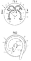
- the cable plate 1 is the invention Connection device shown with its front 10 while 2 shows the cable plate 1 with its rear side 11 is shown.
- the cable plate 1 consists of an electrical conductive material, such as aluminum, die-cast zinc or metallized plastic, and can be in one piece.
- the cable plate 1 On the front 10, the cable plate 1 has four elongated Recordings 12, 13, 14 and 15, each between one common branch area 16 and one associated Connector bracket 17, 18, 19 or 20 continuous, so without interruption. Extends more precisely the receptacle 12 starting from the branch area 16 to the connector holder 17.
- the receptacle 13 extends between the branch area 16 and the connector holder 18, while the recording 15 between the common branch area 16 and the connector holder 19 and the receptacle 14 between the common branch area 16 and the connector holder 20 extends.
- the elongated receptacles 12, 13, 14 and 15 are on the side limited by side walls that extend parallel to each other and normal to the surface of the cable plate 1 on the Stick out front 10. This is exemplified in FIG. 4 shown for the receptacle 13 at its end, the receptacle 13 has the side walls 21 and 22. The bottom of the shots is through the surface of the cable plate 1 at the front 10 provided.
- the cable plate 1 has a central through hole 38 which the Passage of the cable 7 from the rear 11 into the branch area 16 on the front 10 of the cable plate 1 allows.
- Each of the connector holders 17, 18, 19 and 20 has one frame-shaped plan, which is designed such that a connector 5 in dimension in the connector holder can be included. Any connector bracket 17, 18, 19, 20 thus becomes perpendicular from the surface protruding from the front 10 of the cable plate 1 Sidewalls formed.
- the connector holder is again an example in FIG 18, the four vertical side walls 25, 26, 27, 28, the side walls 25 and 26 to each other opposite are parallel and the side walls 27 and 28 opposite to each other parallel and at right angles to the other side walls 25 and 26 arranged frame-like are.
- the side wall 28 has two side by side, however spaced circular, continuous Holes 23 and 24 for the passage of one cable wire each, holes 23 and 24 being the interior of the receptacle 13 with the interior of the connector holder 18 throughout connect.
- the connector holder 18 has an access opening 29, via which, for example, a connector according to the invention 5 can be used.
- the receptacle 13 also has an access opening 30 like the other pictures 12, 14 and 15, via which a pair of wires are inserted into the receptacle 13 can. As shown by way of example in FIG. 8, in FIG Recording 12 inserted a pair of wires 73 and with the connector 5 contacted, in the connector receptacle 17th is inserted.
- FIG 3 an alternative embodiment to execution the connector holder 18 of Figure 4 shown.
- the alternative embodiment has a side wall 28.1 continuous, slot-like opening 28.2, which extends from the Surface of the front 10 of the cable plate 1 to the access opening 29 extends continuously.
- the connector bracket has 18 as well as the other connector holders 17, 19 and 20 locking notches 31 formed on the inside as a locking device to hold one in the connector holder inserted connector 5.
- the cable plate 1 has several vertically protruding supports 32, 33, 34 and 35 for holding the Multi-core cable 7 on the rear 11 of the cable plate 1.
- the cable 7 is spiral wrapped in one plane and lies on the back 11 the cable plate 1.
- the cable plate 1 is on the rear 11 a circumferential web 36 which, when the cable plate 1 used for example in a flush-mounted box is, strikes the bottom of the flush-mounted box, so that the cable wrap kept in one area for excess cable length is that through the bottom of the flush-mounted box, the rotating one Web 36 and the surface of the rear 11 of the cable plate 1 is limited.
- the supports 32, 33, 34, 35 are such on the rear 11 arranged that a way for winding the excess Cable length is specified to the winding during assembly facilitate.
- a cable clamp 37 is provided at the rear 11 of the cable plate for fixing and Strain relief of the cable 7 on the rear 11 of the cable plate 1 serves.
- the cover plate 2 (see Figure 8) is formed in one piece and is made of a conductive material, for example Aluminum, gray cast iron or similar.
- the cover plate 2 is positively placed on the cable plate 1 and has an underside facing the front 10 of the cable plate 1 indicates when the cover plate 2 is placed on the cable plate 1 is, and a top that is in opposite Direction away from the cable plate 1 when the cover plate 2 is placed on the cable plate 1.
- the cover plate 2 covers the entire length of the cable plate 1 depends on a number of openings 41 into which the connector holders 17, 18, 19 and 20 and thus also in the Plug connectors 5 protrude inserted connectors 5, to make contact with the contacts of the plug connector 5 to be able to produce.
- the top of the cover plate 2 closes flush with the tops of the side walls 25, 26, 27 and 28 of the Connector brackets.
- the inside outline of every breakthrough 41 thus corresponds to the outer contour of a connector holder 17, 18, 19 and 20 of the cable plate 1.
- contact springs 40 located on the outside of the side walls of the Support the connector brackets if the cover plate 2, as shown in Figure 8, placed on the cable plate 1 is.
- the contact springs 40 make a pronounced ground contact or ground contact between the cover plate 2 and the cable plate 1 ago.
- circumferential webs 42 be formed by the underside of the cover plate 2 protrude vertically and point to the cable plate 1 if the Cover plate 2, as shown in Figure 8, on the cable plate 1 is attached.
- the webs 42 increase the potential Contact area for the contact springs 40 between the Cover plate 2 and the outer outline of the connector holders 17, 18, 19 and 20 of the cable plate 1.
- the cover plate 2 has sections 39 which are the branch area 16, where the individual wire pairs or wires come from the cable 7, and also all access areas or access openings the recordings 12, 13, 14 and 15 over the entire area at the top of the side walls of the connector holders Cover 17, 18, 19, 20. So that is the individual Wires or wire pairs 73, which are in the receptacles 12 are inserted, or the entire branch area, where the wires branch off from the cable, shielded on all sides. Disruptive Radiation of electromagnetic energy to the outside is avoided by the all-round shielding.
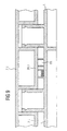
- FIG. 9 one for executing the cover plate 2 is the FIG. 8 alternative embodiment, namely the cover plate 2.1, shown.
- This cover plate 2.1 in turn has shielding sections 39.1, which in turn all access openings 30 of the Recordings 12, 13, 14, 15 and also the branch area 16 of the Cover cable plate 1.
- sections 39.1 are in the execution according to Figure 9 lowered so far that it rest on the top of the side walls of the recordings, if the cover plate 2.1 is placed on the cable plate.
- the shielding sections 39 At extend the design of the cover plate 2 according to Figure 8 the shielding sections 39, however, at the level of Top of the connector brackets.
- the execution of the Cover plate 2.1 according to Figure 9 has the advantage of an improving Shielding especially with regard to crosstalk between individual wire pairs.
- the cover plate 2 a printed circuit board 3 is used, which is from the printed circuit board 3 protruding pin contacts 50 and 51 in the connector 5 engage for contacting, and a connection unit 6 has, which is contacted with the circuit board 3.
- a connection unit 6 On the circuit board 3 are, for example, conductor tracks (not shown) formed which the contact pins 50 and 51 with corresponding Connect contacts of connection unit 6.
- On the circuit board 3 can also electronic components for signal processing and processing should be provided.
- the Circuit board 3 has a ground position.
- Contact springs 43 may be provided, as shown in Figure 8 is a ground contact between the circuit board 3 and the cover plate 2 or the cable plate 1 or ensure or improve. Like in the Figure 8 is shown, the contact springs 43 contact the from the underside of the printed circuit board 3, i.e. from its ground position, stick out the top of the side walls of the connector bracket 18 and thus contact the contact springs 43 the printed circuit board 3 with the cable plate 1.
- the contact springs 43 enclose the paired contacts of the board on all sides, with all-round shielding, that is to say a Faraday Cage provided from the cable to the connection socket that prevents crosstalk to neighboring connections.
- a cover plate 4 is on the cover plate 2 made of plastic, such as in the figure 11 and FIG. 12 is shown.
- the cover plate Figure 11 has two openings 52 through the corresponding one Connection units 6 are accessible from the outside if the cover plate is placed on the cover plate.
- the Version of the cover plate 4.1 of Figure 12 has four Openings 52 and thus serves to cover a connecting device, the four connection units 6, for example four sockets.
- a cable 7 according to the invention is shown in FIG.
- the cable 7 has an outer cable sheath 81 of a number surrounded by wire pairs 83, 84, 85 and 86.
- the shielded wire pairs 83, 84, 85, 86 each with one Connector 5 completed, as in Figures 6 and 7 is shown, can be constructed and also for example is used in Figure 8.
- connectors can to the ends of the wire pairs 83, 84, 84 and 86 by means of Injection molded plastic.
- the cable 7 is not pre-assembled, that is the connectors 5 are not already at the ends of the Fixed wire pairs 83, 84, 85, 86, can also be the connector holder 18 of the type of Figure 4 can be used better shielding compared to the connector holder 18.1 provides, since the wires through the holes 23 and 24 are guided into the interior of the connector 18, and so that all-round shielding is given during the Slot 28.2 of the connector 18.1 of Figure 3 this radiation allows upwards.
- the version with slot and two holes is for the different Types of assembly provided, the slit is used in the case of pre-assembly, and the holes are used when the Cable is struck, with the wires inserted through the holes become.
- the radiation is due to the small wall thickness, if the wires go through the holes, hardly affected.
- FIGS. 6 and 7 of the connector 5 according to the invention shown the two parts formed with an upper part 60 and a lower part 61 is.
- the upper part 60 consists of a cuboid plastic block 60, the sockets 62 and 63 except for their access openings encloses. From the plastic block of the upper part 60 stand out paired insulation displacement terminals 64 and 65, which also are anchored in the plastic block.
- the socket 62 is included integrally connected to the insulation displacement terminal 64, while the Bush 63 is designed in one piece with the insulation displacement terminal 65.
- the lower part 61 has two side by side at a distance from each other trained channels 66, each channel for receiving one end of the cable 7 is designed.
- Right Angle To An insulation displacement channel 67 opens out on an axis of the channel 66 with a rectangular internal crack in the channel 66, the In terms of dimensions, insulation displacement channel 67 for receiving, for example the cutting clamp 64 is designed.
- FIG 7 is a side view of the composite Connector 5 shown, the connection between the Upper part 60 and the lower part 61 shows in more detail.
- the connection between the Upper part 60 and the lower part 61 shows in more detail.
- the figure 7 shows the side of the assembled connector 5, from which the channels 66 for inserting the cable cores are accessible.
- a locking device is formed which a two-sided detent spring 69 with terminal Locking nose 71 exists, which in turn in a locking opening 72 of Lower part 61 engages when the upper part 60 on the lower part 61 is snapped on.
- the detent spring 69 is on the underside from the top 60.
- the top 60 has furthermore, again in duplicate, opposite Latching springs 70 up to the top of the upper part 60 Start on the upper part 60.
- the detent springs 70 are biased towards the outside of the upper part 60 and have each have a detent 74, which is assigned to notches 31 the connector holder 17 into which the connector 5 is inserted, snap to a snap connection between Form
- the detent spring 70 has to the adjacent surface of the upper part 60 a distance 75, the 70 when the detent spring is engaged is present in the connector holder 17. Because of this distance 75 can the detent spring 70 of the upper part 60 the notch 31 of the connector holder 17 are removed, including the notch 73 on the top of the detent spring 70 serves to remove the connector 5 from the connector holder 17 to be able to remove again.
- the rest connection between Connector 5 and connector holder 17 is so designed to be detachable.
- the flush-mounted box is already set and a cable 7 is laterally inserted into the flush-mounted box as usual.
- First is in an end region of the free end of the cable 7 Cable sheath 81 for the required contact length Stripped wire pairs and also the cable shield 82 in this Area removed.
- the wire pairs 83, 84, 85 and 86 are now separated from each other.
- the excess length of the Cable on the back 11 of the cable plate 1 spirally under Help the supports 32, 33, 34 and 35 wound and the stripped end of the cable 7 is through the through hole 38 inserted through which the area of stripped end of the cable 7 in the branch area 16 the front 10 of the cable plate 1 arrives.
- For train protection the cable clamp 37 on the rear 11 of the cable plate 1 screwed down.
- the individual wire pairs are now in the respective recordings of the cable plate 1 inserted.
- the bend or the course of the core recordings 12, 13, 14 and 15 of the cable plate 1 is designed such that a Kinking or excessive bending of the veins prevented what will otherwise damage the wires could.
- the cable plate 1 connector holders of the type as shown in Figure 4 is, ie with wire openings 23 and 24, has.
- the free ends of the pair of wires 73 can then in the openings 23 and 24 and thus in the one behind Channels 66 introduced from the receptacle 12 until they are in the insulation displacement channels 67 of the lower part 61 intervene.
- the upper part 60 of the connector 5 on the lower part 61 in the connector holder 17 placed, the insulation displacement terminals 64 and 65 in the engage assigned insulation displacement channels 67.
- the deformation the cable cores is a widening 68 of the respective channel 66 of the lower part 61 of the connector 5 recorded, as shown schematically in Figure 5.
- the pair of wires 83 is now contacted with the connector 5 and housed in the intended receptacle 12. Should additional wire pairs with assigned connectors on the Cable plate 1 are connected, proceed as above explained with the wire pair 83 and the connector 5 has been.
- the cable plate 1 in the flush-mounted box (not shown) inserted until the rear Web 36 strikes the bottom of the flush-mounted box.
- the cover plate 2 is inserted into the flush-mounted box and placed positively on the cable plate 1.
- the cover plate 2 is on the cable plate 1 by the pressure the contact springs 40 held.
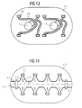
- FIG. 13 shows a further embodiment of the invention Connecting device with a double design Cable plate 1.1 shown for a double socket, if is compared with the cable plate 1 of Figure 1.
- To the Connection device with the cable plate 1.1 can two Cables with four wire pairs each from the rear of the cable plate 1.1 be connected here, as from the two Through holes 1.2 and 1.3 follows.
- the connector brackets this embodiment can again like that in the Figures 3 and 4 shown connector holders designed his.
- the recordings for the cable cores can be made accordingly the embodiment of Figure 8 can be designed.
- the too 13 embodiment of the cover plate, printed circuit board and cover plate are in accordance with the specifications of Cable plate 1.1 of Figure 13 in compliance with the the embodiment of Figure 8 explained electrical properties designed.
- FIG. 14 Yet another embodiment of the connecting device according to the invention can be seen in FIG. 14, in which again only an associated cable plate 1.31 is shown is.
- This cable plate 1.3 is for a purely front Installation of two cables. It has one on the front the main plate 1.4 of the cable plate 1.3, the continuously on the front of the cable plate 1.31 for left side of a first cable and to the right side Recording a second cable is designed.
- the Main shot 1.4 branches off side shots 1.5, whereby the secondary shots 1.5 symmetrical to an axis of symmetry A branch the main shot 1.4 and are formed as can be seen in FIG. 14.
- Each secondary admission 1.5 leads to a connector holder one that follows the pattern of the connector bracket of the figure 3 or 4 can be formed.
- the transition between the main shot 1.4 and each secondary shot 1.5 runs rounded or gradually or conically narrowing in the connector bracket 1.6 ending to again too strong and therefore otherwise damaging the cable Prevent bending of the cable core.
- To every side channel 1.5 is a mirror image of another secondary channel 1.51 adjacent, which has the same clear cross-sectional narrowing like secondary channel 1.5 and from secondary channel 1.5 in the branch area separated from the main channel 1.4 by a web 1.52 is.
- Cable clamps 1.7 are on the cable plate for train protection 1.31 provided.
- the cover plate, circuit board and Cover plate are according to the design specifications of the Figure 14 shown cable plate 1.3 designed.
- the Cable plate 1.31 is intended for the construction of a double socket.
Landscapes
- Details Of Connecting Devices For Male And Female Coupling (AREA)
Applications Claiming Priority (2)
| Application Number | Priority Date | Filing Date | Title |
|---|---|---|---|
| DE10023083 | 2000-05-11 | ||
| DE2000123083 DE10023083A1 (de) | 2000-05-11 | 2000-05-11 | Verbindungsvorrichtung, Steckverbinder, Kabel und zugehöriges System |
Publications (1)
| Publication Number | Publication Date |
|---|---|
| EP1154528A2 true EP1154528A2 (fr) | 2001-11-14 |
Family
ID=7641655
Family Applications (1)
| Application Number | Title | Priority Date | Filing Date |
|---|---|---|---|
| EP20010106839 Withdrawn EP1154528A2 (fr) | 2000-05-11 | 2001-03-19 | Dispositif de connexion, connecteur électrique, cable et système |
Country Status (2)
| Country | Link |
|---|---|
| EP (1) | EP1154528A2 (fr) |
| DE (1) | DE10023083A1 (fr) |
Cited By (1)
| Publication number | Priority date | Publication date | Assignee | Title |
|---|---|---|---|---|
| US11136819B2 (en) * | 2015-07-01 | 2021-10-05 | Hunter Douglas Inc. | Cable restraint bracket of an architectural covering assembly |
Families Citing this family (3)
| Publication number | Priority date | Publication date | Assignee | Title |
|---|---|---|---|---|
| DE20200613U1 (de) | 2002-01-16 | 2002-05-02 | Sick AG, 79183 Waldkirch | Elektrisches Anschlusselement |
| DE102008055997A1 (de) * | 2008-11-05 | 2010-05-06 | Wilo Se | Abdeckung einer Unterputzdose |
| DE102023117006A1 (de) * | 2023-06-28 | 2025-01-02 | Bayerische Motoren Werke Aktiengesellschaft | Steckverbinderhalter zum Halten zumindest eines Steckverbinders, Fahrzeug sowie Verfahren |
Family Cites Families (5)
| Publication number | Priority date | Publication date | Assignee | Title |
|---|---|---|---|---|
| DE58908708D1 (de) * | 1989-09-29 | 1995-01-12 | Siemens Ag | Anschlusseinheit zum Anschliessen und Verbinden von elektrischen Leitungen. |
| DE9010834U1 (de) * | 1990-07-20 | 1990-10-04 | BTR Blumberger Telefon- und Relaisbau Albert Metz, 78176 Blumberg | Durchgangsverbinderdose |
| DE4225326C2 (de) * | 1992-07-31 | 1994-07-14 | Eberle Gmbh | Anschlußvorrichtung |
| DE19630352C2 (de) * | 1996-07-26 | 2000-04-06 | Siemens Ag | Modul zum Anschluß von Aktoren und/oder Sensoren |
| DE19733202C1 (de) * | 1997-08-01 | 1999-04-08 | Telefunken Microelectron | Schneid-Klemm-Vorrichtung |
-
2000
- 2000-05-11 DE DE2000123083 patent/DE10023083A1/de not_active Withdrawn
-
2001
- 2001-03-19 EP EP20010106839 patent/EP1154528A2/fr not_active Withdrawn
Cited By (3)
| Publication number | Priority date | Publication date | Assignee | Title |
|---|---|---|---|---|
| US11136819B2 (en) * | 2015-07-01 | 2021-10-05 | Hunter Douglas Inc. | Cable restraint bracket of an architectural covering assembly |
| US11655674B2 (en) | 2015-07-01 | 2023-05-23 | Hunter Douglas Inc. | Elongated actuation member to engage a printed circuit board of an architectural covering assembly |
| US12018528B2 (en) | 2015-07-01 | 2024-06-25 | Hunter Douglas Inc. | Architectural covering assembly with an end cap having a printed circuit board and an actuation member |
Also Published As
| Publication number | Publication date |
|---|---|
| DE10023083A1 (de) | 2001-11-15 |
Similar Documents
| Publication | Publication Date | Title |
|---|---|---|
| EP0809331B1 (fr) | Connecteur à fiche multipolaire ayant une prise avec au moins une fiche pour le raccordement électrique et mécanique des conducteurs électriques | |
| DE69505508T2 (de) | Geschirmte elektrische verbinderanordnung mit abgeschirmtem gehaeuse | |
| DE4402837C2 (de) | Elektrisches Installationssystem, gebildet durch Flachkabel und Anschlußvorrichtung | |
| DE69812262T2 (de) | Elektrischer Kabelsteckverbinder | |
| DE112007000173B4 (de) | Kabelbaum mit einer Rauschunterdrückung | |
| DE102017219078A1 (de) | Abzweigstruktur und Drahtkabelbaum | |
| DE112019006474B4 (de) | Verbinder und Verbinderstruktur | |
| EP0849840B1 (fr) | Connecteur blindé multipolaire pour câbles | |
| EP0700126B1 (fr) | Fiche pour câble multiconducteur | |
| DE4234451C1 (de) | Anschlußdose für abgeschirmte Kabel, insbesondere für Datenübertragungskabel | |
| DE3201142A1 (de) | Steckverbinder | |
| DE69019225T2 (de) | Verfahren zum Abzweigen und Festklemmen eines mehradrigen, abgeschirmten elektrischen Kabelstranges und Verbinder hierfür. | |
| DE112019006501T5 (de) | Anschlussmodul und Verbinder | |
| EP1667285A2 (fr) | Maintien de câble | |
| DE102019100225A1 (de) | Steckverbindung mit Schirmauflage | |
| DE2251020B2 (de) | Anschlussvorrichtung | |
| AT409564B (de) | Anschlussdose für ein datennetz | |
| DE10023083A1 (de) | Verbindungsvorrichtung, Steckverbinder, Kabel und zugehöriges System | |
| EP4386993A1 (fr) | Boîte de raccordement pour un réseau de données et de communication | |
| EP0174578B2 (fr) | Fiche d'appareil avec filtre électrique d'antiparasitage connecté à celle-ci | |
| DE4324798C1 (de) | Abgeschirmtes Gehäuse für ein Verteilerfeld | |
| DE102024003184B3 (de) | Kabelverbindungsvorrichtung | |
| DE4331143C1 (de) | Anschlußdose zur Bildung einer Anschlußeinrichtung für ein Datennetz | |
| AT406809B (de) | Anschlussdose und anschlusskabel zur bildung einer anschlusseinrichtung für ein datennetz | |
| DE4404807A1 (de) | Abgeschirmte Steckbuchse |
Legal Events
| Date | Code | Title | Description |
|---|---|---|---|
| PUAI | Public reference made under article 153(3) epc to a published international application that has entered the european phase |
Free format text: ORIGINAL CODE: 0009012 |
|
| AK | Designated contracting states |
Kind code of ref document: A2 Designated state(s): AT BE CH CY DE DK ES FI FR GB GR IE IT LI LU MC NL PT SE TR |
|
| AX | Request for extension of the european patent |
Free format text: AL;LT;LV;MK;RO;SI |
|
| RAP1 | Party data changed (applicant data changed or rights of an application transferred) |
Owner name: CCS TECHNOLOGY, INC. |
|
| STAA | Information on the status of an ep patent application or granted ep patent |
Free format text: STATUS: THE APPLICATION IS DEEMED TO BE WITHDRAWN |
|
| 18D | Application deemed to be withdrawn |
Effective date: 20031001 |