EP1154878B1 - Rückschlagfreier hammer - Google Patents
Rückschlagfreier hammer Download PDFInfo
- Publication number
- EP1154878B1 EP1154878B1 EP99967098A EP99967098A EP1154878B1 EP 1154878 B1 EP1154878 B1 EP 1154878B1 EP 99967098 A EP99967098 A EP 99967098A EP 99967098 A EP99967098 A EP 99967098A EP 1154878 B1 EP1154878 B1 EP 1154878B1
- Authority
- EP
- European Patent Office
- Prior art keywords
- socket
- canister
- tool head
- hammer
- handle
- Prior art date
- Legal status (The legal status is an assumption and is not a legal conclusion. Google has not performed a legal analysis and makes no representation as to the accuracy of the status listed.)
- Expired - Lifetime
Links
- 239000000463 material Substances 0.000 claims abstract description 24
- 239000000945 filler Substances 0.000 claims abstract description 21
- 230000009969 flowable effect Effects 0.000 claims abstract description 17
- 229910000831 Steel Inorganic materials 0.000 claims abstract description 12
- 239000010959 steel Substances 0.000 claims abstract description 12
- 210000000078 claw Anatomy 0.000 claims abstract description 8
- 239000008188 pellet Substances 0.000 claims abstract description 8
- 238000004519 manufacturing process Methods 0.000 claims abstract description 4
- 239000002184 metal Substances 0.000 claims description 14
- 238000000034 method Methods 0.000 claims description 11
- 230000013011 mating Effects 0.000 claims description 4
- 230000008878 coupling Effects 0.000 claims 1
- 238000010168 coupling process Methods 0.000 claims 1
- 238000005859 coupling reaction Methods 0.000 claims 1
- 229910000760 Hardened steel Inorganic materials 0.000 abstract description 10
- 230000035939 shock Effects 0.000 abstract description 3
- 238000009432 framing Methods 0.000 description 7
- 238000005253 cladding Methods 0.000 description 4
- 238000010276 construction Methods 0.000 description 3
- 230000002093 peripheral effect Effects 0.000 description 3
- 238000009826 distribution Methods 0.000 description 2
- 239000011152 fibreglass Substances 0.000 description 2
- 230000001739 rebound effect Effects 0.000 description 2
- 229920001169 thermoplastic Polymers 0.000 description 2
- 239000004416 thermosoftening plastic Substances 0.000 description 2
- 238000003466 welding Methods 0.000 description 2
- 241000333074 Eucalyptus occidentalis Species 0.000 description 1
- 239000004677 Nylon Substances 0.000 description 1
- 239000000853 adhesive Substances 0.000 description 1
- 230000001070 adhesive effect Effects 0.000 description 1
- 230000009286 beneficial effect Effects 0.000 description 1
- 230000001419 dependent effect Effects 0.000 description 1
- 239000007769 metal material Substances 0.000 description 1
- 238000012986 modification Methods 0.000 description 1
- 230000004048 modification Effects 0.000 description 1
- 239000002991 molded plastic Substances 0.000 description 1
- 229920001778 nylon Polymers 0.000 description 1
- 239000011236 particulate material Substances 0.000 description 1
- 230000008569 process Effects 0.000 description 1
- 230000009467 reduction Effects 0.000 description 1
- 230000004044 response Effects 0.000 description 1
- 239000007787 solid Substances 0.000 description 1
- 239000012815 thermoplastic material Substances 0.000 description 1
Images


Classifications
-
- B—PERFORMING OPERATIONS; TRANSPORTING
- B25—HAND TOOLS; PORTABLE POWER-DRIVEN TOOLS; MANIPULATORS
- B25G—HANDLES FOR HAND IMPLEMENTS
- B25G1/00—Handle constructions
- B25G1/01—Shock-absorbing means
-
- B—PERFORMING OPERATIONS; TRANSPORTING
- B25—HAND TOOLS; PORTABLE POWER-DRIVEN TOOLS; MANIPULATORS
- B25D—PERCUSSIVE TOOLS
- B25D1/00—Hand hammers; Hammer heads of special shape or materials
- B25D1/12—Hand hammers; Hammer heads of special shape or materials having shock-absorbing means
Definitions
- This invention relates to non-recoil hammers as disclosed in the preamble of claim 1, and to related processes for manufacturing such hammers.
- Such a hammer is known from document wo 97/04925.
- Hammers of the type have a tool head defining one or more metal impact members are well known in the art, for use in striking a target or work surface.
- such hammers are available in a broad range of tool head sizes, shapes and weights in accordance with the particular task or tasks to be performed, such as driving nails or breaking concrete.
- the tool head is commonly constructed from a tough grade and preferably hardened steel to provide durable impact members for extended service life.
- One example of such hammers comprises a conventional carpenter's framing hammer having a hardened steel tool head with a central aperture or eyehole for assembly with a tool handle, wherein the tool head defines an impact member and a nail removal claw at opposite ends thereof.
- the tool head of such framing hammer is used for a variety of tasks, including driving nails, removal of nails, and other prying and wedging functions.
- One problem encountered with traditional hammers of the type having a metal tool head relates to hammer rebound or recoil from a target surface after striking an impact blow. More specifically, when the hammer is swung by a worker to strike a target surface, most of the kinetic energy is transmitted from the impact member of the hammer to the target surface at the moment of impact. However, a portion of this kinetic energy is not transmitted to the target surface, but instead causes the hard-faced tool head to rebound or recoil from the target surface. This rebound effect thus prevents complete or substantially complete energy transfer to the target surface, thereby typically requiring an increased number of impact blows to perform a given task, e.g., driving a nail.
- this rebound effect requires the worker to swing the hammer with an increased force, or to use a hammer with a heavier tool head, in order to complete a task with a reduced number of impact blows. Moreover, the worker must maintain a grasp of the hammer following an impact blow with sufficient strength to resist rebound forces in order to prevent loss of control. All of these factors undesirably increase the degree of strength and skill required for proper and safe hammer usage.
- Nonrecoil or so-called deadblow hammers have been developed in an attempt to reduce or eliminate rebound of the tool head from a target surface following an impact blow.
- Such nonrecoil or deadblow hammers typically have a tool head defined by a hollow core canister filled partially with a relatively high mass and flowable filler material such as steel shot pellets, steel pins, or the like.
- the hollow canister is protectively encased in whole or in part within a molded jacket or cladding constructed from a selected tough and durable thermoplastic material such as nylon.
- the filler material shifts and slides about within the hollow canister to absorb and dissipate the impact force in a manner which effectively counteracts any resultant rebound force.
- a greater proportion of the kinetic energy is transmitted from the tool head to the target surface in the course of each blow, to permit performance of a given task in a reduced number of blows, or alternately to permit use of a hammer having a lighter tool head.
- less strength and skill are required to control the hammer following each blow. For examples, of such nonrecoil impact tools, see U.S.
- Patents 5,262,113 and 5,375,486, WO 97/04925 discloses a hammer, comprising a head and an adjoining handle having a grip portion, the head of the hammer being provided with at least one impact surface and a cavity, which is at least partly filled with a particulate material so as to dampen the recoil of the hammer, whereby the handle of the hammer comprises a rigid, longitudinally extending element, one end of which is securely connected to the hammer head and the other end of which is provided with a counterweight, the mass distribution of the hammer is concentrated substantially to the hammer head and the counterweight, and the length and rigidity of the handle as well as said mass distribution of the hammer are selected so as to impart to the hammer, upon a stroke thereof, a recoil movement corresponding to the natural movement of a human hand holding said grip portion of the handle, while at the same time minimising the vibrations of the handle at said gripping portion.
- nonrecoil hammers have generally been limited to mallets and the like having relatively soft impact faces designed to avoid marking or damage to the target surface, or alternately to include metal-faced caps designed to mount upon a tool head formed primarily from relatively soft or nonmetallic materials.
- Such hammers have generally been ill-suited for use, for example, in a typical carpentry or framing environment wherein a hardened steel tool head is desired.
- the present invention relates to an improved hammer or other striking tool of the type having a rigid tool head of hardened steel or the like to define at least one hard-faced impact member, wherein the tool head contains a flowable filler material of relatively high mass to provide the hammer with substantial nonrecoil characteristics following an impact blow to a target surface.
- an improved nonrecoil or deadblow hammer and the related production method are disclosed respectively in independant claims 1 and 10 wherein a tool head of hardened steel or the like is formed with a hollow socket containing a flowable filler material of small steel pellets adapted to absorb or dissipate shock forces and thereby substantially reduce or eliminate rebound when an impact blow is struck by the hammer.
- the tool head comprises a central body having at least one impact member formed thereon for striking a target surface, wherein the central body has the hollow socket formed therein for seated reception of a hollow canister containing the flowable filler material.
- the canister is preassembled with a tool handle which extends downwardly from the tool head through a handle port formed at the base or lower end of the socket.
- the tool head formed from hardened steel or the like defines the hollow socket which opens upwardly for nested and substantially seated reception of the hollow canister containing the flowable filler material.
- the canister defines an opposing pair of end faces seated respectively in substantial abutting relation with a matingly shaped pair of end walls lining the opposite ends of the socket.
- these end walls within the socket may be formed respectively at the inboard sides of front and rear tool work members, such as a front impact member and a cleft-shaped rear nail removal claw in the case of a carpenter's framing hammer.
- the canister is preassembled with a tool handle which in one form may be constructed as a fiberglass pultrusion and then assembled with the canister as by encasing all or part of the canister and handle within a suitable thermoplastic molded cladding.
- a tool handle which in one form may be constructed as a fiberglass pultrusion and then assembled with the canister as by encasing all or part of the canister and handle within a suitable thermoplastic molded cladding.
- a tool handle which in one form may be constructed as a fiberglass pultrusion and then assembled with the canister as by encasing all or part of the canister and handle within a suitable thermoplastic molded cladding.
- Such hollow canister preassembled with a tool handle is shown and described, for example, in U.S. Patents 5,262,113 and 5,375,486, which are incorporated by reference herein.
- the canister is partially filled with the flowable filler material, and seated within the upwardly open socket formed in the tool head. In this position,
- the flowable filler material within the canister shifts in the direction of the impact blow to absorb and dissipate shock forces in a manner which focuses the impact energy upon the target surface while reducing or eliminating any significant rebound.
- the canister containing the filler material is tightly constrained within its opposite end faces seated against the inboard end walls of the tool head lining the socket, resulting in efficient energy transfer between the canister and the tool head.
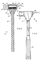
- an improved nonrecoil or deadblow hammer referred to generally in FIGS. 7-9 by the reference numeral 10 includes a tool head 12 of the type formed from a hard and preferably metal material such as hardened steel.
- This tool head 12 has an open socket 14 (FIG. 7) formed therein to receive and contain a relatively high mass flowable filler material 16 (FIG. 8), such as steel shot pellets or the like, to provide the hammer 10 with substantial nonrecoil or deadblow characteristics during normal use.
- the flowable filler material 16 is contained within a hollow canister 18 (FIG. 7 and 8) which is preassembled with a tool handle 20, followed by seated fitting of the canister 18 into the socket 14 formed in the hard metal tool head 12.
- the improved hammer 10 of the present invention is designed for use in the broad range of manually operated impact tool tasks wherein a hard metal tool head is preferred or required, and further wherein potential marking or damage to a target surface in response to impact blows is not a significant concern.
- the illustrative drawings show the tool head 12 in a geometry to include front and rear work members in the form of a front impact member 22 defining a hard-surfaced impact face 24, and a rear cleft-shaped nail removal claw 26, in conformance with the construction of a conventional so-called carpenter's framing hammer.
- Such framing hammer desirably includes the front impact member 22 and the rear claw 26 of relatively hard steel for performing a range of tasks such as nail driving and nail pulling.
- the remainder of the tool head 12 is also desirable for the remainder of the tool head 12 to be constructed from a rigid and hard material such as a hardened steel body formed integrally with the front and rear work members 22, 26 so that the hammer can also be used for a variety of other tasks, including but not limited to wedging, prying, etc.
- the present invention provides the improved hammer 10 with all of these desirable characteristics, but in addition provides the hammer with beneficial nonrecoil or deadblow characteristics for improved delivery of the energy of an impact blow to a target surface with reduced hammer rebound and resultant reduced worker fatigue.
- the tool head 12 is shown in FIGS. 4-7 to include a central body 28 having the front impact member 22 and the rear nail removal claw 26 formed at opposite ends thereof.
- the tool head 12 is formed as a unitary metal structure, preferably from a hardened steel.
- the central body 28 has the socket 14 formed therein with an upwardly open configuration.
- this socket 14 comprises a relatively large and upwardly open cavity of generally rectangular shape lined by upstanding front and rear end walls 30 and 32, and by a pair of upstanding side walls 34.
- the front and rear end walls 30, 32 are disposed generally in axial alignment with and thus define inboard end walls for the front and rear work members 22, 26 of the hammer.
- the base or lower end of the socket 14 is defined by a peripheral rim 36 extending inwardly from the lower ends of the end walls 30, 32 and the adjoining side walls 34.
- This peripheral rim 36 defines a support surface for seated and secure nested reception of the canister 18, as will be described in more detail.
- the rim 36 merges in turn with a downwardly open handle port 38 defined in the illustrative drawings by a downwardly extending hollow skirt 40 of generally truncated conical shape formed as part of the tool head 12 in substantial alignment with a vertical center axis of the overlying socket 14.
- the cross sectional area defined by the handle port 38 is significantly smaller that the cross sectional area defined by the open upper or top end of the socket 14.
- the canister 18 comprises a generally rectangular hollow case or core having a size and shape for nested and substantially mated reception into the socket 14 of the tool head 12. More specifically, the canister 18 may be formed from a suitable sturdy material such as a selected metal or molded plastic, to have a hollow interior 42 (FIG. 3) and initially to include at least one opening such as an open front end 44 (FIGS. 3 and 8) to permit partial filling of the canister with the relatively high mass flowable filler material 16, e.g., metal shot pellets or pins or the like.
- a suitable sturdy material such as a selected metal or molded plastic
- the opening 44 is closed, as by means of an end plate 46 suitably affixed over or nested within the canister front end.
- the canister 18 is sized and shaped to fit relatively tightly within the socket 14 as viewed in FIG. 8, with the front end plate 46 abutting the adjacent inboard front end wall 30 of the tool head, and with a rear end face 48 of the canister abutting the adjacent inboard rear end wall 32 of the tool head 12.
- the front and rear end walls 30, 32 of the tool head 12 will normally be formed with a slight taper or draft extending upwardly and outwardly relative to the socket 14, and the front and rear faces 46, 48 of the assembled canister 18 will be formed with a mating taper or draft for tight abutting fit against the end walls 30, 32.
- a similar taper may be imparted to the socket side walls 34, in which case the side walls 50 of the canister 18 would be formed with a mating taper for tight abutting fit therewith.
- a lower or bottom wall 52 of the canister 18 seats upon the peripheral rim 36 within the socket 14, when the canister is fully and properly inserted into the socket 14 as viewed in FIG. 8.
- a tapered stem 54 of truncated conical shape extends downwardly from the underside of the canister bottom wall 52, within the tool head skirt 40.
- This tapered stem 54 comprises a convenient structure for connection of the canister 18 to an upper end of the tool handle 20, wherein this connection is protectively located within and surrounded by the skirt 40, as shown best in FIG. 8.
- the tool handle 20 extends downwardly from the canister stem 54, through the handle port 38 defined by the skirt 40, for convenient manual grasping during hammer use.
- a resilient grip 56 (FIG. 9) may be mounted on a lower region of the tool handle 20.
- the canister 18 is initially preassembled with the tool handle 20.
- the canister stem 54 can be securely attached to the upper end of a metal tool handle by means of welding or the like, as a connection point indicated by reference numeral 58 (FIGS. 1-3 and 8).
- the canister 18 may be assembled with the tool handle 20 and encased in whole or in part within a suitable thermoplastic molded cladding (not shown).
- the molded cladding would normally leave the end faces 46, 48 of the canister unexposed for subsequent intimate abutting engagement with the inboard end walls 30, 32 lining the tool head socket 14.
- the flowable filler material 16 is placed into the hollow canister 18 prior to or following canister attachment to the tool handle 20, and the canister 18 is closed by means of the end plate 46 to seal the filler material therein.
- the preassembled canister 18 and tool handle 20 are then assembled with the tool head 12 by sliding the handle 20 downwardly through the handle port 38 (FIG. 7) until the canister 18 is fully seated within the socket 14 (FIG. 8).
- the periphery of the canister bottom wall 52 is firmly seated upon the support rim 36 at the bottom of the socket 14, and the opposing end faces 46, 48 of the canister are in relatively tight and intimate abutting engagement with the inboard end walls 30, 32 lining the socket.
- a lower end of the skirt 40 is sized and shaped for relatively snug-fit sliding reception and support of the handle 20.
- a cap plate 60 (FIGS.
- the hammer 10 can be employed by a worker to perform any of the traditional impact, prying, etc., functions normally associated with a conventional carpenter's framing hammer.
- a target surface such as the head of a nail
- the flowable filler material 16 within the tool head shifts in the direction of the blow at the moment of impact to focus the impact energy upon the target surface.
- little energy is available for causing any significant recoil or rebound of the hammer from the target surface following the impact blow.
- the improved hammer of the present invention is beneficially capable of performing tasks with a reduced effort, either in terms of the number of blows or in terms of the force of each blow, in comparison with a conventional solid steel tool head hammer of comparable weight.
- the improved hammer of the present invention permits a hammer of lighter weight to be used.
- the nonrecoil characteristics of the hammer 10 result in further reductions in worker effort and fatigue.
- the hollow canister 18 is supported by the tool head 12 in a secure and stable manner, by virtue of the snug nested fit within the socket 14, in combination with the secondary support provided by the skirt 40 engaging the handle 20 at a point below the canister/handle connection site 58.
Landscapes
- Engineering & Computer Science (AREA)
- Mechanical Engineering (AREA)
- Percussive Tools And Related Accessories (AREA)
- Developing Agents For Electrophotography (AREA)
- Impact Printers (AREA)
- Diaphragms For Electromechanical Transducers (AREA)
- Saccharide Compounds (AREA)
Claims (18)
- Rückschlagfreier Hammer (10), aufweisend einen Metallwerkzeugkopf (12), der einen zentralen Körper (28) einschließt und mindestens ein Schlagglied (22) an einer Vorderseite des zentralen Körpers bestimmt, weiterhin aufweisend ein fließfähiges Füllmaterial (16), das aus kleinen Stahlkörnern besteht, die im Metallwerkzeugkopf enthalten sind, und weiterhin aufweisend einen Stiel (20),
dadurch gekennzeichnet, dass im zentralen Körper (28) eine nach oben offene Hülse (14) ausgeformt ist, wobei die offene Hülse (14) durch ein Paar im Allgemeinen aufrechter vorderer und hinterer Stimwände (30, 32) eingefasst ist, die mit einem Paar im Allgemeinen aufrechter Seitenwände (34), die einander gegenüberliegen, verbunden sind, und weiterhin einschließend eine nach oben weisende Auflagefläche an einem unteren Ende der Hülse (14), wobei in der Auflagefläche eine Stielöffnung ausgeformt ist,
dass der Hammer weiterhin einen hohlen Kanister (18) aufweist, dessen Größe und Form so gewählt sind, dass er in die Hülse (14) schiebbar ist, der auf der Auflagefläche aufsitzt und der vordere und hintere Stirnflächen am Kanister (18) einschließt, die gewährleisten, dass er relativ dicht bzw. im Wesentlichen passend an den vorderen und hinteren Stirnwänden, die die Hülse einfassen, anliegt,
dass das fließfähige Füllmaterial (16), das aus kleinen Stahlkörnern besteht, im Kanister (18) enthalten ist und diesen teilweise füllt, und
dass der Stiel (20) mit dem Kanister (18) verbunden ist und sich vom Kanister (18) aus nach unten und durch die Stielöffnung erstreckt, wenn der Kanister (18) in die Hülse geschoben ist. - Der rückschlagfreie Hammer nach Anspruch 1, dadurch gekennzeichnet, dass der Metallwerkzeugkopf (12) einen Stahlwerkzeugkopf aufweist.
- Der rückschlagfreie Hammer nach Anspruch 1 oder 2, dadurch gekennzeichnet, dass der zentrale Körper (28) ein Paar vorderer und hinterer Arbeitsglieder aufweist, die im Allgemeinen an einander gegenüberliegenden vorderen und hinteren Enden des zentralen Körpers angeordnet sind, wobei das vordere Arbeitsglied das Schlagglied (22) aufweist.
- Der rückschlagfreie Hammer nach Anspruch 3, dadurch gekennzeichnet, dass das hintere Arbeitsglied eine hintere gespaltene Finne zum Ziehen von Nägeln (26) aufweist und das Schlagglied (22) eine vordere Schlagfläche (24) bestimmt.
- Der rückschlagfreie Hammer nach einem der vorangehenden Ansprüche, weiterhin einschließend eine auf dem Werkzeugkopf angebrachte Abdeckplatte (60) zum Einschließen des Kanisters in der Hülse.
- Der rückschlagfreie Hammer nach einem der vorangehenden Ansprüche, weiterhin einschließend einen elastischen Handgriff (56), der in einem unteren Bereich des Stiels angebracht ist.
- Der rückschlagfreie Hammer nach einem der vorangehenden Ansprüche, dadurch gekennzeichnet, dass der Werkzeugkopf (12) weiterhin ein hinteres Arbeitsglied einschließt, das an einem hinteren Ende des zentralen Körpers ausgeformt und dabei im Allgemeinen auf das Schlagglied ausgerichtet ist, wobei die vorderen und hinteren Stimwände innerhalb der Hülse im Allgemeinen auf das Schlagglied und das hintere Arbeitsglied ausgerichtet sind.
- Der rückschlagfreie Hammer nach einem der vorangehenden Ansprüche, weiterhin einschließend Mittel zum Schließen der offenen Hülse, um den Kanister (18) darin einzuschließen.
- Der rückschlagfreie Hammer nach einem der vorangehenden Ansprüche, dadurch gekennzeichnet, dass der Werkzeugkopf (12) weiterhin eine hohle Einfassung (40) einschließt, die sich von der Hülse aus nach unten erstreckt und ein oberes Ende des Stiels umschließt, wobei die Einfassung ein unteres Ende hat, dessen Größe und Form so gewählt sind, dass der Stiel relativ satt anliegend in dieses untere Ende hineingleiten kann.
- Verfahren zur Herstellung eines rückschlagfreien Hammers (10), umfassend die folgenden Schritte:Bereitstellen eines Metallwerkzeugkopfs (12), der einen zentralen Körper (28) einschließt, in dem eine nach oben offene Hülse (14) ausgeformt ist, und der weiterhin mindestens ein Schlagglied (22) an einer Vorderseite des zentralen Körpers bestimmt, wobei die offene Hülse durch ein Paar im Allgemeinen aufrechter vorderer und hinterer Stirnwände (30, 32) eingefasst ist, die mit einem Paar im Allgemeinen aufrechter Seitenwände (34), die einander gegenüberliegen, verbunden sind, und weiterhin einschließend eine nach oben weisende Auflagefläche an einem unteren Ende der Hülse, wobei in der Auflagefläche eine Stielöffnung ausgeformt ist,teilweises Füllen eines hohlen Kanisters (18) mit einem fließfähigen Füllmaterial (16), das aus kleinen Stahlkörnern besteht, wobei Größe und Form des hohlen Kanisters so gewählt sind, dass er in die Hülse schiebbar ist, der Kanister auf der Auflagefläche aufsitzt und vordere und hintere Stirnflächen am Kanister einschließt, die gewährleisten, dass er relativ dicht bzw. im Wesentlichen passend an den vorderen und hinteren Stirnwänden, die die Hülse einfassen, anliegt,Verbinden eines Stiels (20) mit dem Kanister, undgleitendes Einführen des Stiels in die Stielöffnung, so dass sich der Stiel vom Werkzeugkopf aus nach unten erstreckt, während der Kanister und die Hülse ineinander geschoben werden.
- Das Verfahren nach Anspruch 10, dadurch gekennzeichnet, dass der Metallwerkzeugkopf einen Stahlwerkzeugkopf aufweist.
- Das Verfahren nach Anspruch 10 oder 11, dadurch gekennzeichnet, dass der Werkzeugkopf ein Paar vorderer und hinterer Arbeitsglieder aufweist, die im Allgemeinen an einander gegenüberliegenden vorderen und hinteren Enden des zentralen Körpers angeordnet sind.
- Das Verfahren nach einem der vorangehenden Ansprüche 10 bis 12, dadurch gekennzeichnet, dass das vordere bzw. das hintere Arbeitsglied das Schlagglied (22), das eine vordere Schlagfläche (24) bestimmt, bzw. eine hintere gespaltene Finne zum Ziehen von Nägeln (26) aufweist.
- Das Verfahren nach einem der vorangehenden Ansprüche 10 bis 13, weiterhin einschließend den Schritt des Anbringens einer Abdeckplatte (60) auf dem Werkzeugkopf zum Einschließen des Kanisters in der Hülse.
- Das Verfahren nach einem der vorangehenden Ansprüche 10 bis 14, weiterhin einschließend den Schritt des Anbringens eines elastischen Handgriffs (56), der in einem unteren Bereich des Stiels angebracht wird.
- Das Verfahren nach einem der vorangehenden Ansprüche 10 bis 15, dadurch gekennzeichnet, dass der Werkzeugkopf weiterhin ein hinteres Arbeitsglied einschließt, das an einem hinteren Ende des zentralen Körpers ausgeformt und dabei im Allgemeinen auf das Schlagglied ausgerichtet ist, wobei die vorderen und hinteren Stirnwände innerhalb der Hülse im Allgemeinen auf das Schlagglied und das hintere Arbeitsglied ausgerichtet sind.
- Das Verfahren nach einem der vorangehenden Ansprüche 10 bis 16, weiterhin einschließend den Schritt des Schließens der offenen Hülse, um den Kanister darin einzuschließen.
- Das Verfahren nach einem der vorangehenden Ansprüche 10 bis 17, dadurch gekennzeichnet, dass der Werkzeugkopf weiterhin eine hohle Einfassung (40) einschließt, die sich von der Hülse aus nach unten erstreckt und ein oberes Ende des Stiels umschließt, wobei die Einfassung ein unteres Ende hat, dessen Größe und Form so gewählt sind, dass der Stiel relativ satt anliegend in dieses untere Ende hineingleiten kann.
Applications Claiming Priority (3)
| Application Number | Priority Date | Filing Date | Title |
|---|---|---|---|
| US09/236,851 US6227075B1 (en) | 1999-01-25 | 1999-01-25 | Nonrecoil hammer |
| US236851 | 1999-01-25 | ||
| PCT/US1999/026300 WO2000043165A2 (en) | 1999-01-25 | 1999-11-08 | Nonrecoil hammer |
Publications (3)
| Publication Number | Publication Date |
|---|---|
| EP1154878A2 EP1154878A2 (de) | 2001-11-21 |
| EP1154878A4 EP1154878A4 (de) | 2003-05-07 |
| EP1154878B1 true EP1154878B1 (de) | 2005-02-02 |
Family
ID=22891244
Family Applications (1)
| Application Number | Title | Priority Date | Filing Date |
|---|---|---|---|
| EP99967098A Expired - Lifetime EP1154878B1 (de) | 1999-01-25 | 1999-11-08 | Rückschlagfreier hammer |
Country Status (6)
| Country | Link |
|---|---|
| US (2) | US6227075B1 (de) |
| EP (1) | EP1154878B1 (de) |
| AT (1) | ATE288340T1 (de) |
| AU (1) | AU2344400A (de) |
| DE (1) | DE69923601D1 (de) |
| WO (1) | WO2000043165A2 (de) |
Families Citing this family (28)
| Publication number | Priority date | Publication date | Assignee | Title |
|---|---|---|---|---|
| US6595087B2 (en) | 2001-11-21 | 2003-07-22 | Snap-On Technologies, Inc. | Encapsulated dead blow hammer with improved skeleton |
| US6640447B2 (en) | 2001-12-18 | 2003-11-04 | Kenneth K. Wickline | Dead-blow recoilless axe |
| US6945138B1 (en) | 2002-07-24 | 2005-09-20 | Kreitzer David F | Recoiling striking device |
| US6904829B2 (en) * | 2002-09-17 | 2005-06-14 | Anthony Krallman | Deadblow hammer |
| US20070113709A1 (en) * | 2002-09-17 | 2007-05-24 | Anthony Krallman | Deadblow hammer |
| US7168338B2 (en) * | 2004-11-29 | 2007-01-30 | Snap-On Incorporated | Dead blow hammer with composite holder |
| US8597016B2 (en) | 2005-11-23 | 2013-12-03 | Milgard Manufacturing Incorporated | System for producing pultruded components |
| US8101107B2 (en) | 2005-11-23 | 2012-01-24 | Milgard Manufacturing Incorporated | Method for producing pultruded components |
| US7875675B2 (en) | 2005-11-23 | 2011-01-25 | Milgard Manufacturing Incorporated | Resin for composite structures |
| US7901762B2 (en) | 2005-11-23 | 2011-03-08 | Milgard Manufacturing Incorporated | Pultruded component |
| US8499665B2 (en) * | 2006-08-30 | 2013-08-06 | Stanley Black & Decker, Inc. | Torsion control hammer grip |
| NZ571026A (en) * | 2008-09-05 | 2010-09-30 | Maxwell Derek Belsey | An impact tool having a movable weight contained within the handle of the tool |
| US8047099B2 (en) | 2009-02-09 | 2011-11-01 | Stanley Black & Decker, Inc. | Large strike face hammer |
| US20140103089A1 (en) * | 2012-10-12 | 2014-04-17 | Patrick Hale | Fastening tool and method of operation |
| US10464196B2 (en) * | 2012-10-12 | 2019-11-05 | Patrick Hale | Board fastening tool |
| US20140216210A1 (en) * | 2013-02-05 | 2014-08-07 | Timothy J. NEAR | Striking device with sliding weight for increasing impact force |
| TWI447002B (zh) * | 2013-03-07 | 2014-08-01 | Earthquake hammer structure | |
| US9789597B2 (en) | 2014-03-07 | 2017-10-17 | Estwing Manufacturing Company, Inc. | Striking tool with attached striking surface |
| WO2015134106A1 (en) | 2014-03-07 | 2015-09-11 | Estwing Manufacturing Company, Inc. | Aluminum striking tools |
| US20170282342A1 (en) * | 2016-04-05 | 2017-10-05 | Sing Ray Corporation | Shock absorbing hammer |
| USD829074S1 (en) | 2016-09-21 | 2018-09-25 | Estwing Manufacturing Company, Inc. | Hammer |
| US11358263B2 (en) | 2018-02-21 | 2022-06-14 | Milwaukee Electric Tool Corporation | Hammer |
| KR101970610B1 (ko) * | 2018-03-02 | 2019-04-19 | 한아툴스(주) | 망치의 무게 중심이동 개선과 타격부의 교체를 편리하게 한 망치 |
| US11833651B2 (en) | 2019-02-07 | 2023-12-05 | Milwaukee Electric Tool Corporation | Hammer with hardened textured striking face |
| CN114945445A (zh) | 2020-01-10 | 2022-08-26 | 米沃奇电动工具公司 | 锤子 |
| US11642768B2 (en) | 2020-07-15 | 2023-05-09 | Snap-On Incorporated | Dead blow hammer head |
| CN112372584B (zh) * | 2020-10-23 | 2021-12-03 | 浦江县颐硕科技开发有限公司 | 一种双头非牛顿式敲击锤及其调节方法 |
| USD1021598S1 (en) | 2022-05-11 | 2024-04-09 | Snap-On Incorporated | Dead blow hammer |
Family Cites Families (58)
| Publication number | Priority date | Publication date | Assignee | Title |
|---|---|---|---|---|
| US404663A (en) | 1889-06-04 | Device for securing tools to handles | ||
| US657422A (en) | 1898-06-20 | 1900-09-04 | Avery Stamping Company | Shovel. |
| US894155A (en) | 1907-05-04 | 1908-07-21 | Cary W Layton | Tool-handle. |
| US1374336A (en) | 1919-12-13 | 1921-04-12 | John S Surbaugh | Handle and blade connection |
| US1435851A (en) | 1920-04-14 | 1922-11-14 | Isham Harry Stevens | Rubberset cushioned implement handle and insert thimble |
| US1755236A (en) | 1926-07-02 | 1930-04-22 | Wood Shovel And Tool Company | Shovel and shovel handle |
| US2052616A (en) | 1932-12-27 | 1936-09-01 | Ncr Co | Key and method of manufacturing the same |
| US2031556A (en) | 1933-07-31 | 1936-02-18 | Wood Shovel & Tool Company | Shovel |
| US2063774A (en) | 1936-02-03 | 1936-12-08 | Washington Matthew William | Shovel |
| US2205769A (en) | 1937-06-28 | 1940-06-25 | Ernest J Sweetland | Implement handle |
| US2238104A (en) | 1940-01-04 | 1941-04-15 | Union Fork And Hoe Company | Tool handle |
| US2517902A (en) | 1944-08-31 | 1950-08-08 | George C Luebkeman | Molding process and means |
| FR1064418A (fr) | 1952-10-15 | 1954-05-13 | Manches d'outils incassables et outils indémanchables | |
| US2850331A (en) | 1954-09-13 | 1958-09-02 | Fayette R Plumb Inc | Handle connection for percussive tool |
| US2837381A (en) | 1955-11-21 | 1958-06-03 | Oscar L Sarlandt | Reinforced tool handle attachment |
| US2948649A (en) | 1956-12-14 | 1960-08-09 | Pancherz Hans Johannes Joachim | Method of manufacturing sections and rods of glass fibre-reinforced plastic |
| US3018140A (en) | 1959-05-12 | 1962-01-23 | True Temper Corp | Adhesive connection for tool handle |
| US3232355A (en) | 1963-10-16 | 1966-02-01 | Animal Trap Co America | Garden tool handle |
| US3556888A (en) | 1967-06-23 | 1971-01-19 | Glastrusions | Pultrusion machine and method |
| US3549189A (en) | 1968-08-09 | 1970-12-22 | Michael Alosi | Tool handle |
| US3620159A (en) | 1969-07-24 | 1971-11-16 | James L Gould | Marking hammer |
| US3762453A (en) | 1971-05-12 | 1973-10-02 | Stanley Works | Hand tool handle |
| GB1376180A (en) | 1971-12-31 | 1974-12-04 | Spear Jackson Tools Ltd | Spades and shovels |
| US3753602A (en) | 1972-01-28 | 1973-08-21 | Nupla Corp | Adapter for fiberglass tool handles and other fiberglass connections |
| US3819288A (en) | 1972-01-28 | 1974-06-25 | Nupla Corp | Adapter for fiberglass tool handles and other fiberglass connections |
| US3915782A (en) | 1973-03-12 | 1975-10-28 | Nupla Corp | Method of attaching hand grips to fiberglass tool handles |
| US3877826A (en) | 1973-03-12 | 1975-04-15 | Stanley Works | Handle connection for impact tools |
| US3874433A (en) | 1973-09-12 | 1975-04-01 | Stanley Works | Hand tool connection and trim collar therefor |
| US3917421A (en) | 1974-05-28 | 1975-11-04 | Nupla Corp | Insert for attaching fiberglass tool handles |
| US4085784A (en) | 1975-06-26 | 1978-04-25 | Fish Herbert L | Impact tool and handle assembly therefor |
| US4039012A (en) | 1976-01-12 | 1977-08-02 | C. E. S., Inc. | Non-rebound hammer |
| US4030847A (en) | 1976-06-10 | 1977-06-21 | Nupla Corporation | Adapter for fiberglass tool handles and other fiberglass connections |
| US4050727A (en) | 1976-08-10 | 1977-09-27 | The Union Fork & Hoe Company | Hand-shovel assembly and method of producing it |
| US4139930A (en) | 1977-10-11 | 1979-02-20 | Cox Charles T | All-metal hammer handle adapter construction |
| ZA784458B (en) | 1978-08-07 | 1979-12-27 | Modern Inventions Ltd | Handle |
| US4287640A (en) | 1979-08-17 | 1981-09-08 | Ixl Manufacturing Co., Inc. | Tool handle and method of making same |
| GB2061364B (en) | 1979-10-09 | 1983-05-18 | Hoyle Marine Ltd | Hook fastenings |
| US4291998A (en) | 1980-06-05 | 1981-09-29 | The Budd Company | Replacement handle for a tool |
| GB2093398A (en) | 1981-02-17 | 1982-09-02 | Nat Plastics Ltd | Reinforced hollow or tubular articles |
| US4424183A (en) | 1982-07-06 | 1984-01-03 | Baker International Corporation | Destructible core structure and method for using same |
| USRE32364E (en) | 1982-08-13 | 1987-02-24 | Flexible core for tool handles | |
| US4605254A (en) | 1982-08-13 | 1986-08-12 | Carmien Joseph A | Reinforced handle and method of making same |
| US4570988A (en) | 1982-08-13 | 1986-02-18 | Carmien Joseph A | Reinforced tool handle and method of manufacturing same |
| US4451073A (en) | 1982-08-13 | 1984-05-29 | Carmien Joseph A | Flexible core for tool handles |
| SE8300614D0 (sv) | 1983-02-07 | 1983-02-07 | Electrolux Ab | Sett att framstella ett med halrum forsett plastforemal |
| FR2555098B1 (fr) | 1983-11-18 | 1986-08-22 | Skf Et Cie Ste Financiere Immo | Procede pour realiser un taraudage dans un tube ou une bielle en un materiau composite |
| US4697481A (en) | 1985-02-21 | 1987-10-06 | Maeda Shell Service Co., Ltd. | Integrally molded hammer with separated head and handle cores |
| US4639029A (en) | 1985-08-09 | 1987-01-27 | Kolonia Robert A | Tool handle |
| US4743481A (en) | 1986-11-26 | 1988-05-10 | Flex Technologies, Inc. | Molding process for articles having an irregular shaped internal passage |
| US4831901A (en) * | 1987-04-29 | 1989-05-23 | Kinne Arnold L | Carpenters hammer double jolt |
| US5031272A (en) | 1990-02-28 | 1991-07-16 | Carmien Joseph A | Tool handle and method of attaching a handle to a percussive tool head |
| US5056381A (en) | 1990-02-28 | 1991-10-15 | Carmein Joseph A | Replacement tool handle, hand tool and method |
| US5123304A (en) | 1991-06-10 | 1992-06-23 | Nupla Corporation | Process for attaching tool heads to ends of composite handles |
| US5375486A (en) | 1991-06-10 | 1994-12-27 | Carmien; Joseph A. | Surface protective striking tools |
| US5262113A (en) | 1992-08-06 | 1993-11-16 | Carmien Joseph A | Method of making a plastic encased tool component having a lightweight hollow core |
| DE4331660A1 (de) * | 1993-09-17 | 1995-03-23 | Halder Erwin Kg | Schonhammer |
| SE510427C2 (sv) * | 1995-07-28 | 1999-05-25 | Hultafors Ab | Hammare med motvikt i ändan av skaftet |
| US5960677A (en) * | 1998-03-13 | 1999-10-05 | Carmien; Joseph Allen | Nonrecoil impact tool |
-
1999
- 1999-01-25 US US09/236,851 patent/US6227075B1/en not_active Expired - Fee Related
- 1999-11-08 AU AU23444/00A patent/AU2344400A/en not_active Abandoned
- 1999-11-08 EP EP99967098A patent/EP1154878B1/de not_active Expired - Lifetime
- 1999-11-08 DE DE69923601T patent/DE69923601D1/de not_active Expired - Lifetime
- 1999-11-08 AT AT99967098T patent/ATE288340T1/de not_active IP Right Cessation
- 1999-11-08 WO PCT/US1999/026300 patent/WO2000043165A2/en not_active Ceased
-
2000
- 2000-06-05 US US09/586,841 patent/US6234048B1/en not_active Expired - Fee Related
Also Published As
| Publication number | Publication date |
|---|---|
| AU2344400A (en) | 2000-08-07 |
| EP1154878A4 (de) | 2003-05-07 |
| US6234048B1 (en) | 2001-05-22 |
| WO2000043165A3 (en) | 2000-11-09 |
| US6227075B1 (en) | 2001-05-08 |
| WO2000043165A2 (en) | 2000-07-27 |
| ATE288340T1 (de) | 2005-02-15 |
| EP1154878A2 (de) | 2001-11-21 |
| DE69923601D1 (de) | 2005-03-10 |
Similar Documents
| Publication | Publication Date | Title |
|---|---|---|
| US6227075B1 (en) | Nonrecoil hammer | |
| US7874231B2 (en) | Striking tool | |
| US6128977A (en) | Shock-absorbing claw hammer | |
| TW397743B (en) | Shock-absorbing claw hammer | |
| US8770548B2 (en) | Striking tools | |
| EP2749379B1 (de) | Hammer | |
| CN107073699B (zh) | 用于打击工具的减振机构 | |
| EP1105255A1 (de) | Vibrationsgedämpfter hammer | |
| US5099724A (en) | Striking device | |
| US10464198B1 (en) | Hammer with lightweight handle | |
| US20040154812A1 (en) | Stake driver hand tool | |
| US5123303A (en) | Impact tool, handle assembly and method of attaching handle to head | |
| US20050252345A1 (en) | Non-recoil striking tool and process for making same | |
| US6311582B1 (en) | Deadblow claw hammer | |
| CA2220699A1 (en) | Striking tool head system and common elongated handle for multiple tool head assemblies | |
| US5992270A (en) | Shock absorbing hammer | |
| CN112388577A (zh) | 柱敲击器 | |
| US20230286124A1 (en) | Striking tool and method of operating the same | |
| CA2231058C (en) | Shock-absorbing claw hammer | |
| WO1997010075A1 (en) | Shock absorbing hammer | |
| MXPA98002886A (en) | Horn absorbing shock hammer | |
| WO2000020177A1 (en) | Tool assembly | |
| HK1195032B (en) | Hammer | |
| MXPA98005838A (en) | Hammer of uña de golpe mue | |
| CA2299879A1 (en) | Shock absorbing hammer and handle assembly |
Legal Events
| Date | Code | Title | Description |
|---|---|---|---|
| PUAI | Public reference made under article 153(3) epc to a published international application that has entered the european phase |
Free format text: ORIGINAL CODE: 0009012 |
|
| 17P | Request for examination filed |
Effective date: 20010807 |
|
| AK | Designated contracting states |
Kind code of ref document: A2 Designated state(s): AT BE CH CY DE DK ES FI FR GB GR IE IT LI LU MC NL PT SE |
|
| AX | Request for extension of the european patent |
Free format text: AL;LT;LV;MK;RO;SI |
|
| A4 | Supplementary search report drawn up and despatched |
Effective date: 20030320 |
|
| RIC1 | Information provided on ipc code assigned before grant |
Ipc: 7B 25G 3/02 B Ipc: 7B 25D 1/12 B Ipc: 7B 25D 1/00 A |
|
| 17Q | First examination report despatched |
Effective date: 20030902 |
|
| GRAP | Despatch of communication of intention to grant a patent |
Free format text: ORIGINAL CODE: EPIDOSNIGR1 |
|
| GRAS | Grant fee paid |
Free format text: ORIGINAL CODE: EPIDOSNIGR3 |
|
| GRAA | (expected) grant |
Free format text: ORIGINAL CODE: 0009210 |
|
| RAP1 | Party data changed (applicant data changed or rights of an application transferred) |
Owner name: NUPLA ACQUISITION CORPORATION |
|
| RIN1 | Information on inventor provided before grant (corrected) |
Inventor name: CARMIEN, JOSEPH ALLEN |
|
| AK | Designated contracting states |
Kind code of ref document: B1 Designated state(s): AT BE CH CY DE DK ES FI FR GB GR IE IT LI LU MC NL PT SE |
|
| PG25 | Lapsed in a contracting state [announced via postgrant information from national office to epo] |
Ref country code: NL Free format text: LAPSE BECAUSE OF FAILURE TO SUBMIT A TRANSLATION OF THE DESCRIPTION OR TO PAY THE FEE WITHIN THE PRESCRIBED TIME-LIMIT Effective date: 20050202 Ref country code: LI Free format text: LAPSE BECAUSE OF FAILURE TO SUBMIT A TRANSLATION OF THE DESCRIPTION OR TO PAY THE FEE WITHIN THE PRESCRIBED TIME-LIMIT Effective date: 20050202 Ref country code: IT Free format text: LAPSE BECAUSE OF FAILURE TO SUBMIT A TRANSLATION OF THE DESCRIPTION OR TO PAY THE FEE WITHIN THE PRESCRIBED TIME-LIMIT;WARNING: LAPSES OF ITALIAN PATENTS WITH EFFECTIVE DATE BEFORE 2007 MAY HAVE OCCURRED AT ANY TIME BEFORE 2007. THE CORRECT EFFECTIVE DATE MAY BE DIFFERENT FROM THE ONE RECORDED. Effective date: 20050202 Ref country code: FR Free format text: LAPSE BECAUSE OF NON-PAYMENT OF DUE FEES Effective date: 20050202 Ref country code: FI Free format text: LAPSE BECAUSE OF FAILURE TO SUBMIT A TRANSLATION OF THE DESCRIPTION OR TO PAY THE FEE WITHIN THE PRESCRIBED TIME-LIMIT Effective date: 20050202 Ref country code: CH Free format text: LAPSE BECAUSE OF FAILURE TO SUBMIT A TRANSLATION OF THE DESCRIPTION OR TO PAY THE FEE WITHIN THE PRESCRIBED TIME-LIMIT Effective date: 20050202 Ref country code: BE Free format text: LAPSE BECAUSE OF FAILURE TO SUBMIT A TRANSLATION OF THE DESCRIPTION OR TO PAY THE FEE WITHIN THE PRESCRIBED TIME-LIMIT Effective date: 20050202 Ref country code: AT Free format text: LAPSE BECAUSE OF FAILURE TO SUBMIT A TRANSLATION OF THE DESCRIPTION OR TO PAY THE FEE WITHIN THE PRESCRIBED TIME-LIMIT Effective date: 20050202 |
|
| REG | Reference to a national code |
Ref country code: GB Ref legal event code: FG4D |
|
| REG | Reference to a national code |
Ref country code: CH Ref legal event code: EP |
|
| REG | Reference to a national code |
Ref country code: IE Ref legal event code: FG4D |
|
| REF | Corresponds to: |
Ref document number: 69923601 Country of ref document: DE Date of ref document: 20050310 Kind code of ref document: P |
|
| PG25 | Lapsed in a contracting state [announced via postgrant information from national office to epo] |
Ref country code: SE Free format text: LAPSE BECAUSE OF FAILURE TO SUBMIT A TRANSLATION OF THE DESCRIPTION OR TO PAY THE FEE WITHIN THE PRESCRIBED TIME-LIMIT Effective date: 20050502 Ref country code: GR Free format text: LAPSE BECAUSE OF FAILURE TO SUBMIT A TRANSLATION OF THE DESCRIPTION OR TO PAY THE FEE WITHIN THE PRESCRIBED TIME-LIMIT Effective date: 20050502 Ref country code: DK Free format text: LAPSE BECAUSE OF FAILURE TO SUBMIT A TRANSLATION OF THE DESCRIPTION OR TO PAY THE FEE WITHIN THE PRESCRIBED TIME-LIMIT Effective date: 20050502 |
|
| PG25 | Lapsed in a contracting state [announced via postgrant information from national office to epo] |
Ref country code: DE Free format text: LAPSE BECAUSE OF FAILURE TO SUBMIT A TRANSLATION OF THE DESCRIPTION OR TO PAY THE FEE WITHIN THE PRESCRIBED TIME-LIMIT Effective date: 20050503 |
|
| RAP2 | Party data changed (patent owner data changed or rights of a patent transferred) |
Owner name: NUPLA CORPORATION |
|
| PG25 | Lapsed in a contracting state [announced via postgrant information from national office to epo] |
Ref country code: ES Free format text: LAPSE BECAUSE OF FAILURE TO SUBMIT A TRANSLATION OF THE DESCRIPTION OR TO PAY THE FEE WITHIN THE PRESCRIBED TIME-LIMIT Effective date: 20050513 |
|
| REG | Reference to a national code |
Ref country code: GB Ref legal event code: 732E |
|
| NLT2 | Nl: modifications (of names), taken from the european patent patent bulletin |
Owner name: NUPLA CORPORATION |
|
| NLV1 | Nl: lapsed or annulled due to failure to fulfill the requirements of art. 29p and 29m of the patents act | ||
| REG | Reference to a national code |
Ref country code: CH Ref legal event code: PL |
|
| PGFP | Annual fee paid to national office [announced via postgrant information from national office to epo] |
Ref country code: GB Payment date: 20051024 Year of fee payment: 7 |
|
| PG25 | Lapsed in a contracting state [announced via postgrant information from national office to epo] |
Ref country code: IE Free format text: LAPSE BECAUSE OF NON-PAYMENT OF DUE FEES Effective date: 20051108 Ref country code: CY Free format text: LAPSE BECAUSE OF FAILURE TO SUBMIT A TRANSLATION OF THE DESCRIPTION OR TO PAY THE FEE WITHIN THE PRESCRIBED TIME-LIMIT Effective date: 20051108 |
|
| PG25 | Lapsed in a contracting state [announced via postgrant information from national office to epo] |
Ref country code: MC Free format text: LAPSE BECAUSE OF NON-PAYMENT OF DUE FEES Effective date: 20051130 Ref country code: LU Free format text: LAPSE BECAUSE OF NON-PAYMENT OF DUE FEES Effective date: 20051130 |
|
| PLBE | No opposition filed within time limit |
Free format text: ORIGINAL CODE: 0009261 |
|
| STAA | Information on the status of an ep patent application or granted ep patent |
Free format text: STATUS: NO OPPOSITION FILED WITHIN TIME LIMIT |
|
| 26N | No opposition filed |
Effective date: 20051103 |
|
| EN | Fr: translation not filed | ||
| REG | Reference to a national code |
Ref country code: IE Ref legal event code: MM4A |
|
| GBPC | Gb: european patent ceased through non-payment of renewal fee |
Effective date: 20061108 |
|
| PG25 | Lapsed in a contracting state [announced via postgrant information from national office to epo] |
Ref country code: GB Free format text: LAPSE BECAUSE OF NON-PAYMENT OF DUE FEES Effective date: 20061108 |
|
| PG25 | Lapsed in a contracting state [announced via postgrant information from national office to epo] |
Ref country code: PT Free format text: LAPSE BECAUSE OF NON-PAYMENT OF DUE FEES Effective date: 20050702 |