EP1155329B1 - Procede de mesure d'angles d'attaque eleves et du nombre de mach d'une sonde - Google Patents
Procede de mesure d'angles d'attaque eleves et du nombre de mach d'une sonde Download PDFInfo
- Publication number
- EP1155329B1 EP1155329B1 EP00915828A EP00915828A EP1155329B1 EP 1155329 B1 EP1155329 B1 EP 1155329B1 EP 00915828 A EP00915828 A EP 00915828A EP 00915828 A EP00915828 A EP 00915828A EP 1155329 B1 EP1155329 B1 EP 1155329B1
- Authority
- EP
- European Patent Office
- Prior art keywords
- angle
- attack
- pressure
- measured
- probe
- Prior art date
- Legal status (The legal status is an assumption and is not a legal conclusion. Google has not performed a legal analysis and makes no representation as to the accuracy of the status listed.)
- Expired - Lifetime
Links
- 239000000523 sample Substances 0.000 title claims description 54
- 238000000034 method Methods 0.000 title claims description 21
- 230000003068 static effect Effects 0.000 claims description 28
- 230000002596 correlated effect Effects 0.000 claims description 4
- 238000012360 testing method Methods 0.000 description 7
- 238000013459 approach Methods 0.000 description 5
- 238000004364 calculation method Methods 0.000 description 5
- 238000012937 correction Methods 0.000 description 5
- 238000005094 computer simulation Methods 0.000 description 3
- 230000006870 function Effects 0.000 description 3
- 238000009530 blood pressure measurement Methods 0.000 description 2
- 238000005259 measurement Methods 0.000 description 2
- 230000008901 benefit Effects 0.000 description 1
- 238000011088 calibration curve Methods 0.000 description 1
- 230000008859 change Effects 0.000 description 1
- 238000007796 conventional method Methods 0.000 description 1
- 230000007423 decrease Effects 0.000 description 1
- 230000008569 process Effects 0.000 description 1
- 230000009467 reduction Effects 0.000 description 1
- 230000035945 sensitivity Effects 0.000 description 1
- 238000007493 shaping process Methods 0.000 description 1
- 238000004088 simulation Methods 0.000 description 1
Images



Classifications
-
- G—PHYSICS
- G01—MEASURING; TESTING
- G01P—MEASURING LINEAR OR ANGULAR SPEED, ACCELERATION, DECELERATION, OR SHOCK; INDICATING PRESENCE, ABSENCE, OR DIRECTION, OF MOVEMENT
- G01P13/00—Indicating or recording presence, absence, or direction, of movement
- G01P13/02—Indicating direction only, e.g. by weather vane
- G01P13/025—Indicating direction only, e.g. by weather vane indicating air data, i.e. flight variables of an aircraft, e.g. angle of attack, side slip, shear, yaw
-
- G—PHYSICS
- G01—MEASURING; TESTING
- G01P—MEASURING LINEAR OR ANGULAR SPEED, ACCELERATION, DECELERATION, OR SHOCK; INDICATING PRESENCE, ABSENCE, OR DIRECTION, OF MOVEMENT
- G01P5/00—Measuring speed of fluids, e.g. of air stream; Measuring speed of bodies relative to fluids, e.g. of ship, of aircraft
- G01P5/14—Measuring speed of fluids, e.g. of air stream; Measuring speed of bodies relative to fluids, e.g. of ship, of aircraft by measuring differences of pressure in the fluid
- G01P5/16—Measuring speed of fluids, e.g. of air stream; Measuring speed of bodies relative to fluids, e.g. of ship, of aircraft by measuring differences of pressure in the fluid using Pitot tubes, e.g. Machmeter
- G01P5/165—Arrangements or constructions of Pitot tubes
-
- G—PHYSICS
- G01—MEASURING; TESTING
- G01P—MEASURING LINEAR OR ANGULAR SPEED, ACCELERATION, DECELERATION, OR SHOCK; INDICATING PRESENCE, ABSENCE, OR DIRECTION, OF MOVEMENT
- G01P5/00—Measuring speed of fluids, e.g. of air stream; Measuring speed of bodies relative to fluids, e.g. of ship, of aircraft
- G01P5/14—Measuring speed of fluids, e.g. of air stream; Measuring speed of bodies relative to fluids, e.g. of ship, of aircraft by measuring differences of pressure in the fluid
- G01P5/16—Measuring speed of fluids, e.g. of air stream; Measuring speed of bodies relative to fluids, e.g. of ship, of aircraft by measuring differences of pressure in the fluid using Pitot tubes, e.g. Machmeter
- G01P5/17—Coupling arrangements to the indicating device
- G01P5/175—Coupling arrangements to the indicating device with the determination of Mach number
Definitions
- the present invention relates to a method of utilizing measured pressures from pressure sensing ports on an air vehicle for obtaining accurate indications of static pressure, pitot pressure, and angle of attack at very high angles of attack encountered in high performance air vehicles.
- U.S. Patent No. 5,205,169 provides for inverting the ratio of pressure differentials from sensing ports at high angles of attack, generally above 45°.
- the normal angle of attack ratio (P 1 - P 2 ) / q cm ) is inverted to be q cm /(P 1 - P 2 ) when the denominator q cm approaches zero.
- the present invention resides in a method of using measured pressure signals from an air data sensor to provide accurate corrected pressure parameters according to claim 1.
- the present invention resides in an apparatus for determining angles of attack according to claim 5.
- the present invention relates to a method for correcting measured pressures at high angles of attack, by determining Mach number using an alternate pressure signal and providing in the computation, derived correction factors from a calibrated "look-up" table in an air data computer.
- the calibration data or factors are either directly obtained from wind tunnel tests of the sensor probe configuration in actual operational use, or from computer simulations of such sensors at various Mach numbers and angles of attack.
- the calibration values are used in a conventional manner for determining accurate angle of attack, static pressure, and pitot pressure from the measured pressures.
- the pressures that are measured at the ports are correctable up to angles of attack of in the range of 65°.
- the alternate pressure signal is obtained from an angle of attack measuring port located on the sensing probe at a location where pressure increases as angle of attack increases, and the measured alternate pressure is used when the pressure from one angle sensing port of an angle of attack sensor is larger than the measured pitot pressure.
- the conventional local flow calibration approach is used when the pressure of the angle measuring ports is smaller than the measured pitot pressure.
- the method of the present invention is applicable at angles of attack of between about 30° and 65°. Different shaping of the probe could extend the use of the present invention at angles up to about 90°.
- the calibration values are provided for measured pressures indicating Mach numbers at angles of attack above about 35°.
- the calibration values can be easily placed in memory of an onboard computer to derive accurate readings of angle of attack, static pressure, and pitot pressure from the measure pressures.
- the method is used in general with a cylindrical probe having angle sensing ports on the top and bottom of the probe, but it also is useful for flush mounted probes having angle of attack sensing ports that are sensitive to a change in angle of attack, in conjunction with a forward facing (pitot) pressure sensing port.
- a strut mounted air data sensing probe illustrated generally at 10 is used to obtain pressure measurements for determining angle of attack pitot pressure and from the sensed pressure.
- a support strut 11 is attached to a mounting base 12, that is generally fastened onto the fuselage 13 of an aircraft or air vehicle.
- Probe 10 includes a probe barrel 14 that has a longitudinal axis 16 that is oriented in a selected relationship with respect to a reference axis of the fuselage 13 of the aircraft.
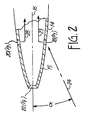
- a forward tapered end 15 is provided with top and bottom angle of attack pressure ports shown at 18 and 20 and a pitot port 22 which is shown at the leading end of the probe barrel and has a center axis coincidental with the barrel axis 16.
- the barrel axis is a center line between the ports 18 and 20.
- the pressure ports 18 and 20 are used for determining the angle of attack or angle of local flow relative to the reference line which coincides with axis 16 which is a reference axis or line of the air vehicle or aircraft.
- angle of attack is indicated as ⁇ in Figures 1 and 2.
- the standard equation for calculating the angle of attack works well.
- These compensation techniques are disclosed, for example, in U.S. Patent No. 4,096,744 as well as U.S. Patent No. 5,205,169.
- the bottom pressure port 18 is considered to have a pressure P 1 provided along a pressure carrying line 23 and the upper or top pressure port 20 that is sensitive to angle of attack is considered to have a pressure P 2 provided along pressure carrying line 28.
- the pitot pressure is P t and provided along a pressure carrying line 25. Additional designations are used with P t to indicate whether it is measured pressure (P t'm ) or local (P t , l ) pressure.
- the pressures are provided to suitable pressure sensors 45, 46 and 47 that provide electrical signals to an air data computer 33.
- the air data computer then provides corrected outputs along lines 34 to instrument displays and controls shown generally at 35, that display measured parameters such as angle of attack, Mach numbers, altitude and the like.
- the computer outputs can be used in fly by wire aircraft controls.
- the angle sensing ports In a flush mounted sensor the angle sensing ports would have an axis in a plane in which an angle of attack is to be measured. As angle of attack in the plane changes, the ports would sense different pressures, to determine angle.
- the basic equation for determining angle of attack is (P 1 - P 2 )/q cm .
- P 1 is pressure measured by the lower angle of attack pressure port 18, and P 2 is the pressure measured by the upper angle of attack pressure port 20 when positive angles of attack are measured.
- q cm is the impact pressure, which is the measured pitot pressure P t'm minus the static pressure (P t'm - P m ).
- P m is (P 1 + P 2 )/2.
- the equation (P m - P l ) /q cl provides local static pressure P l .
- the static pressure ratio for P 1 is equal to (P 1 - P l ) /q cl .
- the static pressure ratio for P 2' the upper port is (P 2 - P l ) /q cl .
- the quantities are defined as follows:
- the present method uses measured pressures to determine Mach number and convert directly to corrected local pitot pressure, local static pressure and probe angle of attack.
- a key feature of the method is the interchanging of P 1 and P t'm (measured pitot pressure) at high angles of attack to determine the local pitot pressure, P t'l and static pressure. All the calibration values for the present invention are determined using available probe calibration data from wind tunnel tests, but using P 1 instead of P t'm for the Mach number for correlating the calibration data.
- a parallel path using this method can be developed to convert from specific measured probe pressures to true values of P (static pressure) and P t (pitot pressure) and aircraft angle of attack. This case requires knowing the flow field on the aircraft at the probe mounting location. Extension of the method to solve for true conditions is straight forward.
- Calibration data for the present invention are:
- Example calibration values for obtaining angle of attack when the pressure ratio on the vertical scale is sensed and calculated from measured pressures are shown in Figure 3.
- the signal shows uniform variations with increasing probe angles of attack to about 70° at lower Mach numbers as determined by P 1 /P m .
- a range up to a probe angle of about 64° shows the best accuracy at higher Mach numbers.
- Reduced sensitivity of the angle of attack signal occurs at the highest Mach numbers.
- Static pressure and pitot pressure calibration curves in Figure 4 and 5 show smooth uniform variations with angle of attack and P 1 /P m . It is recognized the use of different probe shapes or additional multiple ports could benefit this signal.
- the angle of attack value can be directly obtained using an air data computer to interpolate the signal. This gives a value for the ratio using measured pressures, while measured P 1 /P m give the measured Mach number.
- the look-up table 36 ( Figure 1) having the correct angle of attack correlated to the Y axis ratio of measure pressures at measured Mach number (P 1 /P m ) is stored in onboard computer 33, so the correct angle of attack is obtained.
- the angle of attack would be slightly over 60°.
- the accuracy is achieved by providing the P 1/ P m ratio, which at Mach 45 is 1.15, since P 1 becomes a stronger signal as the P t'm signal decreases when angle of attack increases.
- the value used for measured Mach number is P t'm /P m . Additional iterative calculations are necessary and a calculation based on those measured pressures is not as accurate or as direct as the disclosed method when P 1 > P t'm .
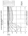
- the corrected static pressure which can be called P l (local static pressure), or true static pressure, is obtained from the results of wind tunnel tests illustrated in Figure 4.
- the predetermined relationships are in the look-up table 36 in the memory of the onboard computer 33.
- the values in the table 36 are shown in the graph of Figure 4.
- the probe angle of attack, ⁇ probe is plotted against the values of the ratio P l /P m obtained by calibration in the wind tunnel or by computer simulation and stored in the look-up table.
- P m can be obtained by the quantity (P 1 + P 2 ) /2 and the local static pressure P l can be easily solved in the onboard air data computer 33 using look-up table values.
- a plot of probe angle of attack, ⁇ probe , versus the quantity P t'l /P 1 as corrected is used. This is done for several different Mach numbers in a wind tunnel or by computer simulation, as indicated.
- the Mach number graph plots are represented using the same angle of attack determined from Figure 3 data.
- the angles of attack shown in Figure 5 are between 30° and 90°, and the plotted values obtained from wind tunnel tests or simulation are stored in a look-up 36 table in the air data computer so that the particular pressure on the vertical axis can be determined by knowing the angle of attack, which in turn is determined as previously disclosed.
- the local pitot pressure P t'l can be easily derived or solved. It will equal the value on the vertical axis for a particular angle of attack, times P 1 . This also can be considered to be the true pitot pressure.
- the look-up tables provide the information that is necessary for obtaining true pitot pressure, true or local static pressure, and angle of attack. The pressures used can be directly measured by the three ports on the probe shown in Figures 1 and 2.
- the measured Mach number is determined by directly measuring P 1 and P 2 and arriving at the ratio P 1 /P m , when P 1 > P t'm which in turn is correlated to angle of attack as shown in Figure 3. Determining measured Mach number by providing directly measured pressures P 1 /P m as opposed to the previously used P t' /P m , enhances operations, and does not require the inverted ratio to be used. It also can be seen that the measurements are more direct, and more easily obtained.
- the present invention reduces the instability of prior art algorithms used at high angles of attack, generally at probe angles above about 35°. It can be seen that the angle of attack curves that are developed and correlated to the quantity P 1 /P m do not have instability across the range of operation between 30° and 90° probe angle of attack. Further, direct pressure measurements are used with the present invention, as opposed to the iterative correction process necessary for mathematical calculations of the local pressures or angle of attack using conventional methods.
- port used for the angle sensing ports means not only a single opening, but also two or more openings on the bottom or top of the probe or sensor that are plumbed together and provide a signal which indicates a pressure changing with angle of attack.
Landscapes
- Engineering & Computer Science (AREA)
- Aviation & Aerospace Engineering (AREA)
- Physics & Mathematics (AREA)
- General Physics & Mathematics (AREA)
- Measuring Fluid Pressure (AREA)
Claims (7)
- Procédé d'utilisation de signaux de pression mesurés par un capteur de données d'air (10) pour fournir des paramètres de pression corrigés, précis, dans lequel le capteur de données d'air possède une paire d'orifices de détection d'angle (18, 20) avec des axes de détection positionnés pour indiquer un angle (α) entre une ligne de référence centrale (16) et une ligne de direction d'écoulement (24) à travers le capteur pour fournir un angle d'attaque, et possédant un orifice de tube de Pitot (22) présentant un axe se trouvant le long de la ligne de référence centrale, et dans lequel les pressions mesurées aux orifices de détection d'angle respectifs diffèrent lorsque la ligne de référence est à un angle par rapport à la ligne de direction d'écoulement avec une plus haute des pressions aux orifices de détection d'angle désignée par P1, une pression à l'autre des orifices de détection d'angle désignée par P2, et une pression à un orifice de tube de Pitot désignée par Pt,m, comprenant la mesure de P1, l'ajout de P1 et de P2 et la division par 2 pour obtenir une quantité Pm et la division de P1 par Pm pour obtenir un nombre Mach mesuré lorsque P1 est supérieure à Pt,m.
- Procédé selon la revendication 1 comprenant en outre la fourniture de valeurs connues d'angle d'attaque pour le capteur de données d'air tracées en fonction de la valeur numérique d'un premier rapport (P1 - Pt,m)/(P1 - Pm) et à des nombres Mach mesurés sélectionnés déterminés par P1/Pm, et fourniture d'une première table de consultation pour déterminer l'angle d'attaque une fois ledit premier rapport et P1/Pm déterminés à partir de pressions mesurées aux orifices de détection.
- Procédé selon la revendication 2 et fournissant une seconde table de consultation stockée, contenant des valeurs prédéterminées de Pℓ/Pm tracées en fonction de l'angle d'attaque, Pℓ étant la pression statique locale, et déterminant la pression statique locale au capteur en corrélant la P1 mesurée par rapport à l'angle d'attaque déterminé selon la revendication 2.
- Procédé selon la revendication 2 comprenant en outre le stockage de valeurs prédéterminées de Pt,ℓ/P1 tracées en fonction de l'angle d'attaque dans une troisième table de consultation, dans lequel Pt,ℓ comprend la pression du tube de Pitot vraie en mesurant la valeur P1 et en corrélant Pt,ℓ/ P1 avec l'angle d'attaque déterminé selon la revendication 2 selon les valeurs stockées dans la troisième table de consultation.
- Dispositif pour déterminer des angles d'attaque à travers une plage comprenant :une sonde (10) possédant un axe de détection et des orifices orientés de manière opposée (18, 20) présentant des axes de mesure positionnés par rapport à un plan contenant l'axe de détection (16) dans lequel un angle d'attaque (α) doit être mesuré par rapport à un axe de direction d'écoulement (24) se trouvant également dans le plan dudit axe de détection, l'un desdits orifices délivrant un signal de plus haute pression que l'autre lorsque l'axe de sonde est à un angle différent de zéro par rapport à l'axe de direction d'écoulement ;un orifice de pression de tube de Pitot (22) sur la sonde possédant un axe globalement parallèle à l'axe de détection pour mesurer les pressions créées par l'écoulement relatif à travers la sonde ;des transducteurs de pression pour délivrer des signaux indiquant les pressions à chacun des orifices ; etun processeur délivrant une sortie (P1 - Pt,m)/(P1 - Pm) et corrélé avec des valeurs calibrées d'angles d'attaque à des nombres Mach mesurés en utilisant le rapport P1/Pm pour déterminer le nombre Mach mesuré lorsque P1 est supérieur à Pt,m, P1 étant la plus haute des pressions aux orifices orientés de manière opposée, Pt,m est la pression du tube de Pitot mesurée à l'orifice du tube de Pitot, et Pm est la quantité (P1 + P2)/2, P2 étant la pression mesurée à l'autre des orifices orientés de manière opposée.
- Dispositif selon la revendication 5, dans lequel le processeur comprend des capteurs de pression pour délivrer des signaux indiquant les pressions aux orifices orientés de manière opposée et à l'orifice au tube de Pitot.
- Dispositif selon la revendication 5, dans lequel les axes de mesure des orifices orientés de manière opposée sont à des angles égaux par rapport à l'axe de détection.
Priority Applications (1)
| Application Number | Priority Date | Filing Date | Title |
|---|---|---|---|
| EP05077735A EP1637891A1 (fr) | 1999-02-22 | 2000-02-22 | Systèmes et procédés pour empêcher l utilisation non autorisée de contenus numériques |
Applications Claiming Priority (3)
| Application Number | Priority Date | Filing Date | Title |
|---|---|---|---|
| US09/255,173 US6305218B1 (en) | 1999-02-22 | 1999-02-22 | Method of and apparatus for using an alternate pressure to measure mach number at high probe angles of attack |
| US255173 | 1999-02-22 | ||
| PCT/US2000/004482 WO2000049419A1 (fr) | 1999-02-22 | 2000-02-22 | Procede de mesure d'angles d'attaque eleves et du nombre de mach d'une sonde |
Related Child Applications (1)
| Application Number | Title | Priority Date | Filing Date |
|---|---|---|---|
| EP05077735A Division EP1637891A1 (fr) | 1999-02-22 | 2000-02-22 | Systèmes et procédés pour empêcher l utilisation non autorisée de contenus numériques |
Publications (2)
| Publication Number | Publication Date |
|---|---|
| EP1155329A1 EP1155329A1 (fr) | 2001-11-21 |
| EP1155329B1 true EP1155329B1 (fr) | 2006-04-26 |
Family
ID=22967166
Family Applications (2)
| Application Number | Title | Priority Date | Filing Date |
|---|---|---|---|
| EP05077735A Withdrawn EP1637891A1 (fr) | 1999-02-22 | 2000-02-22 | Systèmes et procédés pour empêcher l utilisation non autorisée de contenus numériques |
| EP00915828A Expired - Lifetime EP1155329B1 (fr) | 1999-02-22 | 2000-02-22 | Procede de mesure d'angles d'attaque eleves et du nombre de mach d'une sonde |
Family Applications Before (1)
| Application Number | Title | Priority Date | Filing Date |
|---|---|---|---|
| EP05077735A Withdrawn EP1637891A1 (fr) | 1999-02-22 | 2000-02-22 | Systèmes et procédés pour empêcher l utilisation non autorisée de contenus numériques |
Country Status (5)
| Country | Link |
|---|---|
| US (1) | US6305218B1 (fr) |
| EP (2) | EP1637891A1 (fr) |
| AU (1) | AU3703700A (fr) |
| DE (1) | DE60027552T2 (fr) |
| WO (1) | WO2000049419A1 (fr) |
Cited By (1)
| Publication number | Priority date | Publication date | Assignee | Title |
|---|---|---|---|---|
| CN108007667A (zh) * | 2017-11-20 | 2018-05-08 | 北京航天长征飞行器研究所 | 一种高温燃气风洞马赫数测量装置及方法 |
Families Citing this family (23)
| Publication number | Priority date | Publication date | Assignee | Title |
|---|---|---|---|---|
| US6622390B2 (en) * | 2001-08-29 | 2003-09-23 | Rosemount Aerospace Inc. | Method and apparatus for installation and alignment of air data sensing probe |
| US7379839B2 (en) * | 2002-12-23 | 2008-05-27 | Rosemount Aerospace, Inc. | Multi-function air data probes employing neural networks for determining local air data parameters |
| EP1559646A1 (fr) * | 2004-02-02 | 2005-08-03 | Joy | Mesure de pression sur une voile |
| US7257470B2 (en) * | 2004-10-29 | 2007-08-14 | Rosemount Aerospace Inc. | Fault isolation method and apparatus in artificial intelligence based air data systems |
| US20060212181A1 (en) * | 2005-03-16 | 2006-09-21 | Rosemount Aerospace Inc. | Method and apparatus for extending useful range of air data parameter calculation in flush air data systems |
| US7213454B2 (en) * | 2005-04-06 | 2007-05-08 | Rosemount Aerospace Inc. | Method and apparatus for obtaining improved accuracy and range for air data parameters inferred from independent measurements of interdependent pressures |
| US20070130096A1 (en) * | 2005-12-01 | 2007-06-07 | Rosemount Aerospace, Inc. | Fault detection in artificial intelligence based air data systems |
| US7334467B1 (en) | 2006-08-22 | 2008-02-26 | Honeywell International, Inc. | Air data module that ensures sufficient air data performance after exposure to relatively high overpressure |
| JP4415980B2 (ja) | 2006-08-30 | 2010-02-17 | 株式会社日立製作所 | 高抵抗磁石およびそれを用いたモータ |
| US7597018B2 (en) * | 2007-04-11 | 2009-10-06 | Rosemount Aerospace Inc. | Pneumatic line isolation and heating for air data probes |
| FR2916276B1 (fr) * | 2007-05-14 | 2009-08-28 | Airbus France Sas | Dispositif et procede d'estimation d'un angle d'incidence d'un aeronef |
| EP2148088A1 (fr) * | 2008-07-22 | 2010-01-27 | Siemens Aktiengesellschaft | Procédé et arrangement pour le réglage d'angle de calage des pales d'éolienne |
| KR101089989B1 (ko) * | 2009-12-24 | 2011-12-05 | 한국항공우주연구원 | 공기 데이터 센서장치 |
| US8949090B2 (en) * | 2013-01-28 | 2015-02-03 | The Boeing Company | Formation flight control |
| DE102013103150A1 (de) * | 2013-03-27 | 2014-10-02 | Deutsches Zentrum für Luft- und Raumfahrt e.V. | Verfahren zum Ermitteln eines Anstellwinkels |
| US10151214B2 (en) * | 2014-02-05 | 2018-12-11 | United Technologies Corporation | Integral instrumentation in additively manufactured components of gas turbine engines |
| US9821903B2 (en) | 2014-07-14 | 2017-11-21 | The Boeing Company | Closed loop control of aircraft control surfaces |
| US10301042B2 (en) * | 2017-04-11 | 2019-05-28 | General Electric Company | Pitot-static air data test system with automatic dependent surveillance-broadcast (ADS-B) verification |
| CN108562420A (zh) * | 2017-12-26 | 2018-09-21 | 北京航天益森风洞工程技术有限公司 | 一种多孔探针的自动标定系统及方法 |
| US11215631B2 (en) | 2019-10-16 | 2022-01-04 | Honeywell International Inc. | Multi-function air data probe having multi-hole ports used for determining angle of attack, total and static pressure values |
| CN112881004A (zh) * | 2021-01-11 | 2021-06-01 | 中国空气动力研究与发展中心高速空气动力研究所 | 一种空速管风洞校核试验装置及校核试验方法 |
| US11579163B1 (en) | 2021-07-29 | 2023-02-14 | Rockwell Collins, Inc. | Differential pressure angle of attack sensor |
| CN115452313B (zh) * | 2022-11-14 | 2023-03-24 | 中国空气动力研究与发展中心高速空气动力研究所 | 一种声爆试验探针角度敏感性快速标定方法 |
Family Cites Families (16)
| Publication number | Priority date | Publication date | Assignee | Title |
|---|---|---|---|---|
| US2204367A (en) | 1938-05-03 | 1940-06-11 | Square D Co | Trapped self-draining pitot-static tube |
| US3163040A (en) | 1962-01-04 | 1964-12-29 | Rosemount Eng Co Ltd | De-iced pitot static tube |
| US3318146A (en) | 1966-02-14 | 1967-05-09 | Rosemount Eng Co Ltd | Pressure sensing instrument for aircraft |
| US3482445A (en) | 1968-04-25 | 1969-12-09 | Rosemount Eng Co Ltd | Strut mounted dual static tube |
| US4025008A (en) * | 1973-11-27 | 1977-05-24 | Messerschmitt-Bolkow-Blohm Gmbh | Intake control for air utilizing aircraft engines |
| US4096744A (en) | 1975-09-05 | 1978-06-27 | Rosemount Inc. | Pressure sensor for determining airspeed, altitude and angle of attack |
| US4277940A (en) * | 1979-07-25 | 1981-07-14 | United Technologies Corporation | Integral rocket-ramjet closed loop fuel control system |
| US4378696A (en) | 1981-02-23 | 1983-04-05 | Rosemount Inc. | Pressure sensor for determining airspeed altitude and angle of attack |
| US4378697A (en) | 1981-07-06 | 1983-04-05 | Rosemount Inc. | Strut mounted multiple static tube |
| US4615213A (en) | 1983-12-22 | 1986-10-07 | Rosemount Inc. | Pressure sensing instrument for aircraft |
| US4645517A (en) | 1985-09-20 | 1987-02-24 | Rosemount Inc. | Drain manifold for air data sensor |
| US4718273A (en) | 1985-12-31 | 1988-01-12 | The Garrett Corporation | Combination alpha, static and total pressure probe |
| US4836019A (en) | 1987-08-27 | 1989-06-06 | Rosemount Inc. | Compact air data sensor |
| US5025661A (en) | 1989-12-11 | 1991-06-25 | Allied-Signal Inc. | Combination air data probe |
| US5083279A (en) * | 1990-05-09 | 1992-01-21 | Honeywell, Inc. | Canard based high angle of attack air data sensor |
| US5205169A (en) | 1991-08-08 | 1993-04-27 | Rosemount Inc. | Angle of attack sensor using inverted ratio of pressure differentials |
-
1999
- 1999-02-22 US US09/255,173 patent/US6305218B1/en not_active Expired - Lifetime
-
2000
- 2000-02-22 WO PCT/US2000/004482 patent/WO2000049419A1/fr not_active Ceased
- 2000-02-22 EP EP05077735A patent/EP1637891A1/fr not_active Withdrawn
- 2000-02-22 DE DE60027552T patent/DE60027552T2/de not_active Expired - Lifetime
- 2000-02-22 AU AU37037/00A patent/AU3703700A/en not_active Abandoned
- 2000-02-22 EP EP00915828A patent/EP1155329B1/fr not_active Expired - Lifetime
Cited By (2)
| Publication number | Priority date | Publication date | Assignee | Title |
|---|---|---|---|---|
| CN108007667A (zh) * | 2017-11-20 | 2018-05-08 | 北京航天长征飞行器研究所 | 一种高温燃气风洞马赫数测量装置及方法 |
| CN108007667B (zh) * | 2017-11-20 | 2020-02-14 | 北京航天长征飞行器研究所 | 一种高温燃气风洞马赫数测量装置及方法 |
Also Published As
| Publication number | Publication date |
|---|---|
| EP1637891A1 (fr) | 2006-03-22 |
| US6305218B1 (en) | 2001-10-23 |
| WO2000049419A1 (fr) | 2000-08-24 |
| DE60027552D1 (de) | 2006-06-01 |
| EP1155329A1 (fr) | 2001-11-21 |
| DE60027552T2 (de) | 2007-05-10 |
| AU3703700A (en) | 2000-09-04 |
Similar Documents
| Publication | Publication Date | Title |
|---|---|---|
| US6305218B1 (en) | Method of and apparatus for using an alternate pressure to measure mach number at high probe angles of attack | |
| EP0597899B1 (fr) | Capteur d'angle d'attaque, utilisant un rapport inverse de differences de pression | |
| EP1256812B1 (fr) | Correction de l'angle de lacet pour un système de données aérodynamiques multifonctionel à trois sondes | |
| US4096744A (en) | Pressure sensor for determining airspeed, altitude and angle of attack | |
| US3318146A (en) | Pressure sensing instrument for aircraft | |
| US7480548B2 (en) | High-altitude capable wide velocity range flight velocity vector measurement probe and measurement system | |
| US6679112B2 (en) | Total pressure determination with multifunction probe for aircraft | |
| CA2587175C (fr) | Procede et appareil pour determiner une pression d'ecoulement a partir de donnees de densite | |
| US6374190B2 (en) | Method for calibrating an angle sensor and navigation system having an angle sensor | |
| US6452542B1 (en) | Integrated flight management system | |
| EP0632273A1 (fr) | Système de données triaxiales concernant l'air pour des aéronefs | |
| JPS58500217A (ja) | 対気速度、高度および迎え角測定用圧力センサ− | |
| US20090319189A1 (en) | Low cost, unattended weather sensor | |
| US7201067B2 (en) | System and method for determining flow characteristics | |
| US6176130B1 (en) | Flight velocity vector measuring system in wide velocity region using truncated pyramid-shape probe | |
| US5406839A (en) | Incidence probe with multiple pressure inlets | |
| US9068840B2 (en) | Pitot tube velocimeter system | |
| JPH0566538B2 (fr) | ||
| EP0629166A1 (fr) | Systemes de capteurs de pression aerodynamique | |
| CN107101693A (zh) | 非稳态液面多传感器加权系数动态分配方法 | |
| US3739635A (en) | Fuel management system | |
| CN216559501U (zh) | 压力检测校准装置 | |
| EP1750134B1 (fr) | Procédé de caractérisation ratiométrique pour l'amélioration de mesures dans un système de détermination de données aérodynamiques | |
| Pool | PRESSURE SENSING TECHNIQUES | |
| JPS6326735Y2 (fr) |
Legal Events
| Date | Code | Title | Description |
|---|---|---|---|
| PUAI | Public reference made under article 153(3) epc to a published international application that has entered the european phase |
Free format text: ORIGINAL CODE: 0009012 |
|
| 17P | Request for examination filed |
Effective date: 20010903 |
|
| AK | Designated contracting states |
Kind code of ref document: A1 Designated state(s): AT BE CH CY DE DK ES FI FR GB GR IE IT LI LU MC NL PT SE |
|
| AX | Request for extension of the european patent |
Free format text: AL;LT;LV;MK;RO;SI |
|
| RBV | Designated contracting states (corrected) |
Designated state(s): DE FR GB |
|
| 17Q | First examination report despatched |
Effective date: 20050303 |
|
| GRAP | Despatch of communication of intention to grant a patent |
Free format text: ORIGINAL CODE: EPIDOSNIGR1 |
|
| GRAS | Grant fee paid |
Free format text: ORIGINAL CODE: EPIDOSNIGR3 |
|
| GRAA | (expected) grant |
Free format text: ORIGINAL CODE: 0009210 |
|
| AK | Designated contracting states |
Kind code of ref document: B1 Designated state(s): DE FR GB |
|
| REG | Reference to a national code |
Ref country code: GB Ref legal event code: FG4D |
|
| REF | Corresponds to: |
Ref document number: 60027552 Country of ref document: DE Date of ref document: 20060601 Kind code of ref document: P |
|
| ET | Fr: translation filed | ||
| PLBE | No opposition filed within time limit |
Free format text: ORIGINAL CODE: 0009261 |
|
| STAA | Information on the status of an ep patent application or granted ep patent |
Free format text: STATUS: NO OPPOSITION FILED WITHIN TIME LIMIT |
|
| 26N | No opposition filed |
Effective date: 20070129 |
|
| REG | Reference to a national code |
Ref country code: FR Ref legal event code: PLFP Year of fee payment: 17 |
|
| REG | Reference to a national code |
Ref country code: FR Ref legal event code: PLFP Year of fee payment: 18 |
|
| REG | Reference to a national code |
Ref country code: FR Ref legal event code: PLFP Year of fee payment: 19 |
|
| PGFP | Annual fee paid to national office [announced via postgrant information from national office to epo] |
Ref country code: GB Payment date: 20190125 Year of fee payment: 20 Ref country code: FR Payment date: 20190123 Year of fee payment: 20 Ref country code: DE Payment date: 20190122 Year of fee payment: 20 |
|
| REG | Reference to a national code |
Ref country code: DE Ref legal event code: R071 Ref document number: 60027552 Country of ref document: DE |
|
| REG | Reference to a national code |
Ref country code: GB Ref legal event code: PE20 Expiry date: 20200221 |
|
| PG25 | Lapsed in a contracting state [announced via postgrant information from national office to epo] |
Ref country code: GB Free format text: LAPSE BECAUSE OF EXPIRATION OF PROTECTION Effective date: 20200221 |