EP1155830A2 - Dispositif pour solliciter un rouleau d'une machine d'impression avec une force de pression et machine d'impression avec un tel dispositif - Google Patents
Dispositif pour solliciter un rouleau d'une machine d'impression avec une force de pression et machine d'impression avec un tel dispositif Download PDFInfo
- Publication number
- EP1155830A2 EP1155830A2 EP01111492A EP01111492A EP1155830A2 EP 1155830 A2 EP1155830 A2 EP 1155830A2 EP 01111492 A EP01111492 A EP 01111492A EP 01111492 A EP01111492 A EP 01111492A EP 1155830 A2 EP1155830 A2 EP 1155830A2
- Authority
- EP
- European Patent Office
- Prior art keywords
- force
- contact pressure
- generating element
- printing
- roller
- Prior art date
- Legal status (The legal status is an assumption and is not a legal conclusion. Google has not performed a legal analysis and makes no representation as to the accuracy of the status listed.)
- Granted
Links
Images

Classifications
-
- B—PERFORMING OPERATIONS; TRANSPORTING
- B41—PRINTING; LINING MACHINES; TYPEWRITERS; STAMPS
- B41F—PRINTING MACHINES OR PRESSES
- B41F13/00—Common details of rotary presses or machines
- B41F13/08—Cylinders
- B41F13/24—Cylinder-tripping devices; Cylinder-impression adjustments
- B41F13/26—Arrangement of cylinder bearings
- B41F13/32—Bearings mounted on swinging supports
Definitions
- the invention relates to a device for loading a roller of a printing technology Machine with a contact pressure and a printing machine with such Contraption.
- rollers In the case of printing machines, rollers often have to be applied with a contact pressure be, and in many cases it is crucial for the print quality that the Contact force is constant across the width of such a roller.
- rollers which are used by a substrate conveyed printing substrates against the cylinders of several printing modules Press to make the part-color images generated by the print modules as even as possible and to be transferred to the printing substrates in exact register.
- pressure rollers either individually Pressing springs against the cylinders or the pressure rollers all on one support element to arrange and to apply this to springs so that the pressure rollers pressed together against the cylinders.
- the Contact force generated by a corresponding force from the springs is transferred to displaceably arranged bearings of the pressure rollers.
- a constant Contact pressure across the width of the rollers is not, however, satisfactory Way achievable, especially not if this is due to a required high Print quality in a very precise way is required.
- the invention is therefore based on the object of a device at the outset mentioned type in such a way that a constant contact pressure with little effort can be achieved across the width of the rollers.
- the object is achieved in that the roller at one end two two-armed lever is rotatably mounted that the two-armed lever on side parts are rotatably mounted and that at the other ends of the two-armed lever one Cross connection is arranged to the at least one force-generating element attacks.
- the lever transmission of the forces according to the invention distributes them evenly on the respective roller. This also includes inaccuracies in dimensions by rollers or the elements interacting with them, as well Shocks that occur, for example, from the front or rear edges of printing substrates.
- the force-generating element can be designed in various ways.
- On Proposal provides that the force-generating element to apply a permanent Force is formed, which is dimensioned such that the two-armed lever the contact pressure arises.
- it can create a permanent force that the force-generating element is a weight.
- a force generated in this way is always constant, shows hardly any position-dependent differences and no hysteresis, as is the case with springs.
- the force-generating element for the counteracting force is expedient a pneumatic cylinder.
- this is like starting and stopping a roller well controllable and can be designed such that it simultaneously as Damping element works. This way the occurrence of vibrations prevents, for example, those caused by printing substrate leading or trailing edges could be stimulated.
- variable force is formed, which is adjustable such that a desired contact pressure can be achieved.
- variable force is too adjustable so that the contact pressure can be switched off, that is, the roller with it interacting element can be moved away. This also serves to prevent this the deformation of surfaces mentioned above.
- a force-generating element is arranged centrally on the cross-connection, then easily achieved a very constant contact force along a roller.
- variable force is also preferably generated by means of a pneumatic cylinder, with which various forces such as starting and stopping a roller can be easily achieved are.
- the pneumatic cylinder has a good damping effect achieve.
- cross connection is designed as a resilient element, one becomes special good absorption of shocks and pressure fluctuations as well as a very good compensation achieved by inaccuracies. It also serves this purpose if the cross connection is rotatably connected to the levers, the cross connection parallel to the roller should run.
- damping elements can of course also be arranged.
- One It also serves to prevent vibrations when the bearings of the levers in the Side parts are designed as plain bearings.
- the side panels can have housing walls or be separate components that are connected to the housing walls.
- a particularly useful application of the device provides for this Use pressure of the pressure rollers, whereby the contact pressure is generated, the required for optimal transfer of partial color images to a printing substrate is.
- the aforementioned purpose is particularly important, because the uniform and precise force setting for the print quality is crucial Role play. Therefore, it is also proposed to use a printing press, in particular an electrophotographic printing machine with an aforementioned device equip, the rollers on a support for printing substrates opposite of cylinders are arranged, which for transferring the partial color images Print substrates are formed.
- Fig. 1 shows a schematic diagram of the device according to the invention.
- a roller 1 with a contact pressure 3 this is supported at one end by two two-armed levers 4, 5.
- the two-armed levers 4, 5 are mounted on side parts 6 and 7 by means of bearings 14.
- a cross connection 8 At the other ends of the two-armed levers 4, 5 there is a cross connection 8, which is acted upon by a force generating element 9, 9 ', 9 "with a force 10, 10', 10".
- This can be a force-generating element 9 for generating a permanent force 10, a force-generating element 9 'for generating a force 10' opposite to the permanent force 10, or a force-generating element 9 "for generating a variable force 10".
- the representation here is symbolic in nature and will be explained in more detail below.
- the actuating movement of the roller 1 is shown by means of a double arrow 20 and the Adjustment movement of the opposite ends of the levers 4, 5 with the double arrow 21.
- Forces 10, 10 ', 10 "and actuating movements 20 and 21 are used to engage the roller 1 interacting component, not shown here, with the symbolized by three arrows Apply pressure 3.
- the three arrows 3 are intended to illustrate that the Contact pressure 3 is evenly distributed over the entire width of the roller. This is the Main purpose of the invention, which is achieved in that the power transmission by means of the two-armed levers 4, 5 in such a way that the roller 1 with uniform Forces is applied.
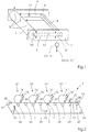
- the diagram in FIG. 2 shows a printing press 2 with a carrier 17 for transporting printing substrates 16 through the printing press 2 in the direction of the arrow 31.
- the printing substrates 16 change from one printing module 19, 19 ', 19 “, 19”' to the other conveyed and thereby printed by cylinders 18, 18 ', 18 ", 18"' of the printing modules 19, 19 ', 19 “, 19”' with partial color images 15, 15 ', 15 ", 15”', which together result in color printing.
- An exact contact pressure 3 and a vibration-free guidance of the printing substrates 16 are required.
- the invention proposes rollers 10, 10 ', 10 ", 10"' which are mounted on the principle described above.
- the carrier 17 is placed over a variety of roles.
- a roller 22 is used to drive of the carrier 17 in the direction of arrow 23. Another role is by the effect a tensioning roller 25.
- a roller 26 pivotable transversely to its axis of rotation is for lateral adjustment of the tape run of the carrier 17 is provided.
- a pulley 27 interacts with a roller 28.
- the roller 28 is used to hang up Print substrates 16 which are to be printed.
- Guide rollers 29 cause certain wrapping of cylinders 18, 18 ', 18 ", 18"' corresponding to the partial color images 15, 15 ', 15 ", 15”' a print image in the form of toner particles for transfer wear on the printing substrates 16.
- the cylinders 15, 15 ', 15 ", 15”' Provide the toner particles directly or via further cylinders (not shown) become.
- the arrows 32 show the direction of rotation of the cylinders 15, 15 ', 15 ", 15”'.
- rollers 10, 10 ', 10 ", 10"' designed as pressure rollers are provided, which can be switched on and off on the underside of the carrier 17.
- Another role 30 is used to remove a printing substrate 16 from the carrier 17.
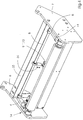
- Fig. 3 shows an embodiment of the device according to the invention with force-generating elements 9 and 9 ', which are designed as a weight 11 and as a pneumatic cylinder 12.
- the weight 11 pulls down and thereby generates the contact pressure 3 of the roller 10.
- the element 9 ' serves to generate the counterforce 10' to regulate this contact pressure 3 or to switch off the contact pressure.
- This element 9 ' is designed as a pneumatic cylinder 12.
- the actuating movement of the pneumatic cylinder 12 is shown by means of the double arrow 34. If the pneumatic cylinder 12 is not active, the contact pressure 3 is generated by the weight 11.
- the two two-armed levers 4, 5 are attached to side parts 6, 7, which are connected to one another by cross struts 33. In this way, the device is designed such that it can be used as a whole in a machine, for example by fastening the side parts 6, 7 in the machine.
- the other functions and the other components reference is made to the basic diagrams above.
- FIG. 4 shows a further exemplary embodiment of the invention, in which an element 9 "for generating a variable force 10" is arranged.
- This element is a pneumatic cylinder 13, which is arranged in the middle of the cross connection 8.
- the cross connection 8 is rotatably suspended on the two-armed levers 4, 5 and has spring properties. These measures result in a very good distribution of force and absorption of shocks and other stresses.
- the levers 4, 5 are supported by means of bearings 14 in side parts 6, 7, which are connected to one another by means of cross struts 33.
- the actuating movement of the pneumatic cylinder 13 is indicated by the double arrow 34.
- the pneumatic cylinder 13 applies the entire force required to set the contact pressure 3.
- the pneumatic cylinder 13 is designed such that it can turn the roller 10 on and off.
Landscapes
- Engineering & Computer Science (AREA)
- Mechanical Engineering (AREA)
- Delivering By Means Of Belts And Rollers (AREA)
- Electrostatic Charge, Transfer And Separation In Electrography (AREA)
- Color Electrophotography (AREA)
- Rotary Presses (AREA)
- Unwinding Webs (AREA)
- Rolls And Other Rotary Bodies (AREA)
- Inking, Control Or Cleaning Of Printing Machines (AREA)
Applications Claiming Priority (4)
| Application Number | Priority Date | Filing Date | Title |
|---|---|---|---|
| DE10024092 | 2000-05-18 | ||
| DE10024092 | 2000-05-18 | ||
| DE10059889A DE10059889A1 (de) | 2000-05-18 | 2000-12-01 | Vorrichtung zur Beaufschlagung einer Walze einer drucktechnischen Maschine mit einer Anpresskraft und Druckmaschine mit einer derartigen Vorrichtung |
| DE10059889 | 2000-12-01 |
Publications (3)
| Publication Number | Publication Date |
|---|---|
| EP1155830A2 true EP1155830A2 (fr) | 2001-11-21 |
| EP1155830A3 EP1155830A3 (fr) | 2003-01-02 |
| EP1155830B1 EP1155830B1 (fr) | 2006-05-31 |
Family
ID=26005707
Family Applications (1)
| Application Number | Title | Priority Date | Filing Date |
|---|---|---|---|
| EP01111492A Expired - Lifetime EP1155830B1 (fr) | 2000-05-18 | 2001-05-11 | Machine d'impression avec dispositifs pour solliciter un rouleau d'impression avec une force de pression |
Country Status (5)
| Country | Link |
|---|---|
| US (1) | US20020020314A1 (fr) |
| EP (1) | EP1155830B1 (fr) |
| JP (1) | JP2002023522A (fr) |
| AT (1) | ATE327889T1 (fr) |
| DE (1) | DE50109925D1 (fr) |
Families Citing this family (2)
| Publication number | Priority date | Publication date | Assignee | Title |
|---|---|---|---|---|
| DE102016215986A1 (de) * | 2016-08-25 | 2018-03-01 | Gallus Druckmaschinen Gmbh | Bearbeitungswerk und Etikettendruckmaschine mit einem solchen Bearbeitungswerk |
| DE102016215988A1 (de) * | 2016-08-25 | 2018-03-01 | Gallus Druckmaschinen Gmbh | Bearbeitungswerk und Etikettendruckmaschine mit einem solchen Bearbeitungswerk |
Family Cites Families (5)
| Publication number | Priority date | Publication date | Assignee | Title |
|---|---|---|---|---|
| US2213130A (en) * | 1938-05-21 | 1940-08-27 | American Stay Company | Printing press |
| GB634213A (en) * | 1947-04-24 | 1950-03-15 | Astra Ivanowna Sark | Improvements relating to multi-colour printing machines |
| FR1494327A (fr) * | 1966-07-29 | 1967-09-08 | Heurtey Sa | Perfectionnements apporté aux dispositifs tendeurs de bande ou produit analogue, dans les installations de traitement continu |
| DE1774631A1 (de) * | 1968-07-30 | 1971-10-21 | Kleinewefers Soehne J | Taenzerwalze |
| DE3232484A1 (de) * | 1981-09-03 | 1983-03-10 | Basf Ag, 6700 Ludwigshafen | Wickelvorrichtung fuer bandstreifen |
-
2001
- 2001-05-07 US US09/850,046 patent/US20020020314A1/en not_active Abandoned
- 2001-05-11 EP EP01111492A patent/EP1155830B1/fr not_active Expired - Lifetime
- 2001-05-11 DE DE50109925T patent/DE50109925D1/de not_active Expired - Lifetime
- 2001-05-11 AT AT01111492T patent/ATE327889T1/de not_active IP Right Cessation
- 2001-05-14 JP JP2001143612A patent/JP2002023522A/ja active Pending
Also Published As
| Publication number | Publication date |
|---|---|
| EP1155830A3 (fr) | 2003-01-02 |
| JP2002023522A (ja) | 2002-01-23 |
| ATE327889T1 (de) | 2006-06-15 |
| US20020020314A1 (en) | 2002-02-21 |
| EP1155830B1 (fr) | 2006-05-31 |
| DE50109925D1 (de) | 2006-07-06 |
Similar Documents
| Publication | Publication Date | Title |
|---|---|---|
| DE60122438T2 (de) | Vorrichtung zum Regulieren des Spaltes zwischen zwei Rollen | |
| EP0238804B1 (fr) | Dispositif de fixation des clichés souples sur les cylindres de clichés dans les rotatives | |
| DE3902923A1 (de) | Bogenfuehrungstrommel fuer bogenrotationsdruckmaschinen | |
| DE3112672C1 (de) | Anschlag fuer die Bogenhinterkante bei Bogenauslegern an bogenverarbeitenden Maschinen | |
| DE2235418A1 (de) | Vorrichtung fuer das querstrecken einer bahn | |
| DE19523076A1 (de) | Vorrichtung zur Erzielung einer einwandfreien Auflage eines Bedruckstoffs in einer Druckmaschine | |
| EP0426022A2 (fr) | Cylindre de plaque dans une machine d'impression | |
| DE69502233T2 (de) | Hilfsantriebsvorrichtung zum Transportieren von Bögen aus Papier oder Karton | |
| EP0668161B1 (fr) | Dispositif pour le transfert de feuilles individuelles sur le cylindre imprimeur d'une machine d'impression rotative de feuilles | |
| DE19856372B4 (de) | Bogentransportband | |
| DE2713994C2 (de) | Bogenhaltevorrichtung einer Bogen- Rotations-Druckmaschine, welche den Druckbogen geringfügig zu verformen vermag | |
| EP1155830B1 (fr) | Machine d'impression avec dispositifs pour solliciter un rouleau d'impression avec une force de pression | |
| WO2014206530A1 (fr) | Groupe d'impression | |
| DE2720673B2 (de) | Vorrichtung zum ungleichförmigen Spannen eines Gummituches in einer Offsetdruckmaschine | |
| DE10059889A1 (de) | Vorrichtung zur Beaufschlagung einer Walze einer drucktechnischen Maschine mit einer Anpresskraft und Druckmaschine mit einer derartigen Vorrichtung | |
| EP0812684B1 (fr) | Machine d'impression comprenant une bande transporteuse de feuilles | |
| DE102011118905A1 (de) | Bearbeitungsstation für eine Stanzmaschine | |
| DE10310375B4 (de) | Bogenzuführtrommel | |
| DE19538322C2 (de) | Einrichtung zur axialen Verstellung von Leitelementen | |
| EP0725026B1 (fr) | Dispositif pour éviter des erreurs de repère | |
| DE19712690A1 (de) | Transmissionsvorrichtung für eine Druckmaschine | |
| DE10001328A1 (de) | Einrichtung zum Aufziehen flexibler Druckformen | |
| DE10035001A1 (de) | Leitwalze | |
| EP0765746B1 (fr) | Machine d'impression et procédé d'alimentation en feuilles sous plusieurs cylindres d'impression | |
| EP4516509B1 (fr) | Dispositif et procédé pour supporter un cylindre d'impression |
Legal Events
| Date | Code | Title | Description |
|---|---|---|---|
| PUAI | Public reference made under article 153(3) epc to a published international application that has entered the european phase |
Free format text: ORIGINAL CODE: 0009012 |
|
| AK | Designated contracting states |
Kind code of ref document: A2 Designated state(s): AT BE CH CY DE DK ES FI FR GB GR IE IT LI LU MC NL PT SE TR |
|
| AX | Request for extension of the european patent |
Free format text: AL;LT;LV;MK;RO;SI |
|
| PUAL | Search report despatched |
Free format text: ORIGINAL CODE: 0009013 |
|
| AK | Designated contracting states |
Kind code of ref document: A3 Designated state(s): AT BE CH CY DE DK ES FI FR GB GR IE IT LI LU MC NL PT SE TR |
|
| AX | Request for extension of the european patent |
Free format text: AL;LT;LV;MK;RO;SI |
|
| RIC1 | Information provided on ipc code assigned before grant |
Free format text: 7B 41F 13/32 A, 7G 03G 15/14 B |
|
| 17P | Request for examination filed |
Effective date: 20030702 |
|
| AKX | Designation fees paid |
Designated state(s): AT BE CH CY DE DK ES FI FR GB GR IE IT LI LU MC NL PT SE TR |
|
| RAP1 | Party data changed (applicant data changed or rights of an application transferred) |
Owner name: EASTMAN KODAK COMPANY |
|
| 17Q | First examination report despatched |
Effective date: 20050603 |
|
| RTI1 | Title (correction) |
Free format text: PRINTING MACHINE WITH MEANS FOR APPLYING A PRESSURE FORCE ON A PRINTING PRESS CYLINDER |
|
| GRAP | Despatch of communication of intention to grant a patent |
Free format text: ORIGINAL CODE: EPIDOSNIGR1 |
|
| GRAS | Grant fee paid |
Free format text: ORIGINAL CODE: EPIDOSNIGR3 |
|
| GRAA | (expected) grant |
Free format text: ORIGINAL CODE: 0009210 |
|
| AK | Designated contracting states |
Kind code of ref document: B1 Designated state(s): AT BE CH CY DE DK ES FI FR GB GR IE IT LI LU MC NL PT SE TR |
|
| PG25 | Lapsed in a contracting state [announced via postgrant information from national office to epo] |
Ref country code: IT Free format text: LAPSE BECAUSE OF FAILURE TO SUBMIT A TRANSLATION OF THE DESCRIPTION OR TO PAY THE FEE WITHIN THE PRESCRIBED TIME-LIMIT;WARNING: LAPSES OF ITALIAN PATENTS WITH EFFECTIVE DATE BEFORE 2007 MAY HAVE OCCURRED AT ANY TIME BEFORE 2007. THE CORRECT EFFECTIVE DATE MAY BE DIFFERENT FROM THE ONE RECORDED. Effective date: 20060531 Ref country code: NL Free format text: LAPSE BECAUSE OF FAILURE TO SUBMIT A TRANSLATION OF THE DESCRIPTION OR TO PAY THE FEE WITHIN THE PRESCRIBED TIME-LIMIT Effective date: 20060531 Ref country code: IE Free format text: LAPSE BECAUSE OF FAILURE TO SUBMIT A TRANSLATION OF THE DESCRIPTION OR TO PAY THE FEE WITHIN THE PRESCRIBED TIME-LIMIT Effective date: 20060531 Ref country code: FI Free format text: LAPSE BECAUSE OF FAILURE TO SUBMIT A TRANSLATION OF THE DESCRIPTION OR TO PAY THE FEE WITHIN THE PRESCRIBED TIME-LIMIT Effective date: 20060531 Ref country code: GB Free format text: LAPSE BECAUSE OF FAILURE TO SUBMIT A TRANSLATION OF THE DESCRIPTION OR TO PAY THE FEE WITHIN THE PRESCRIBED TIME-LIMIT Effective date: 20060531 |
|
| REG | Reference to a national code |
Ref country code: CH Ref legal event code: EP Ref country code: GB Ref legal event code: FG4D Free format text: NOT ENGLISH |
|
| REG | Reference to a national code |
Ref country code: IE Ref legal event code: FG4D Free format text: LANGUAGE OF EP DOCUMENT: GERMAN |
|
| REF | Corresponds to: |
Ref document number: 50109925 Country of ref document: DE Date of ref document: 20060706 Kind code of ref document: P |
|
| PG25 | Lapsed in a contracting state [announced via postgrant information from national office to epo] |
Ref country code: DK Free format text: LAPSE BECAUSE OF FAILURE TO SUBMIT A TRANSLATION OF THE DESCRIPTION OR TO PAY THE FEE WITHIN THE PRESCRIBED TIME-LIMIT Effective date: 20060831 Ref country code: SE Free format text: LAPSE BECAUSE OF FAILURE TO SUBMIT A TRANSLATION OF THE DESCRIPTION OR TO PAY THE FEE WITHIN THE PRESCRIBED TIME-LIMIT Effective date: 20060831 |
|
| PG25 | Lapsed in a contracting state [announced via postgrant information from national office to epo] |
Ref country code: ES Free format text: LAPSE BECAUSE OF FAILURE TO SUBMIT A TRANSLATION OF THE DESCRIPTION OR TO PAY THE FEE WITHIN THE PRESCRIBED TIME-LIMIT Effective date: 20060911 |
|
| PG25 | Lapsed in a contracting state [announced via postgrant information from national office to epo] |
Ref country code: PT Free format text: LAPSE BECAUSE OF FAILURE TO SUBMIT A TRANSLATION OF THE DESCRIPTION OR TO PAY THE FEE WITHIN THE PRESCRIBED TIME-LIMIT Effective date: 20061031 |
|
| NLV1 | Nl: lapsed or annulled due to failure to fulfill the requirements of art. 29p and 29m of the patents act | ||
| GBV | Gb: ep patent (uk) treated as always having been void in accordance with gb section 77(7)/1977 [no translation filed] |
Effective date: 20060531 |
|
| REG | Reference to a national code |
Ref country code: IE Ref legal event code: FD4D |
|
| PLBE | No opposition filed within time limit |
Free format text: ORIGINAL CODE: 0009261 |
|
| STAA | Information on the status of an ep patent application or granted ep patent |
Free format text: STATUS: NO OPPOSITION FILED WITHIN TIME LIMIT |
|
| EN | Fr: translation not filed | ||
| 26N | No opposition filed |
Effective date: 20070301 |
|
| BERE | Be: lapsed |
Owner name: EASTMAN KODAK CY Effective date: 20070531 |
|
| REG | Reference to a national code |
Ref country code: CH Ref legal event code: PL |
|
| PG25 | Lapsed in a contracting state [announced via postgrant information from national office to epo] |
Ref country code: MC Free format text: LAPSE BECAUSE OF NON-PAYMENT OF DUE FEES Effective date: 20070531 |
|
| PG25 | Lapsed in a contracting state [announced via postgrant information from national office to epo] |
Ref country code: LI Free format text: LAPSE BECAUSE OF NON-PAYMENT OF DUE FEES Effective date: 20070531 Ref country code: CH Free format text: LAPSE BECAUSE OF NON-PAYMENT OF DUE FEES Effective date: 20070531 |
|
| PG25 | Lapsed in a contracting state [announced via postgrant information from national office to epo] |
Ref country code: BE Free format text: LAPSE BECAUSE OF NON-PAYMENT OF DUE FEES Effective date: 20070531 |
|
| PG25 | Lapsed in a contracting state [announced via postgrant information from national office to epo] |
Ref country code: GR Free format text: LAPSE BECAUSE OF FAILURE TO SUBMIT A TRANSLATION OF THE DESCRIPTION OR TO PAY THE FEE WITHIN THE PRESCRIBED TIME-LIMIT Effective date: 20060901 Ref country code: FR Free format text: LAPSE BECAUSE OF FAILURE TO SUBMIT A TRANSLATION OF THE DESCRIPTION OR TO PAY THE FEE WITHIN THE PRESCRIBED TIME-LIMIT Effective date: 20070309 |
|
| PG25 | Lapsed in a contracting state [announced via postgrant information from national office to epo] |
Ref country code: AT Free format text: LAPSE BECAUSE OF NON-PAYMENT OF DUE FEES Effective date: 20070511 |
|
| PG25 | Lapsed in a contracting state [announced via postgrant information from national office to epo] |
Ref country code: FR Free format text: LAPSE BECAUSE OF FAILURE TO SUBMIT A TRANSLATION OF THE DESCRIPTION OR TO PAY THE FEE WITHIN THE PRESCRIBED TIME-LIMIT Effective date: 20060531 |
|
| PG25 | Lapsed in a contracting state [announced via postgrant information from national office to epo] |
Ref country code: CY Free format text: LAPSE BECAUSE OF FAILURE TO SUBMIT A TRANSLATION OF THE DESCRIPTION OR TO PAY THE FEE WITHIN THE PRESCRIBED TIME-LIMIT Effective date: 20060531 Ref country code: LU Free format text: LAPSE BECAUSE OF NON-PAYMENT OF DUE FEES Effective date: 20070511 |
|
| PG25 | Lapsed in a contracting state [announced via postgrant information from national office to epo] |
Ref country code: TR Free format text: LAPSE BECAUSE OF FAILURE TO SUBMIT A TRANSLATION OF THE DESCRIPTION OR TO PAY THE FEE WITHIN THE PRESCRIBED TIME-LIMIT Effective date: 20060531 |
|
| PGFP | Annual fee paid to national office [announced via postgrant information from national office to epo] |
Ref country code: DE Payment date: 20120531 Year of fee payment: 12 |
|
| PG25 | Lapsed in a contracting state [announced via postgrant information from national office to epo] |
Ref country code: DE Free format text: LAPSE BECAUSE OF NON-PAYMENT OF DUE FEES Effective date: 20131203 |
|
| REG | Reference to a national code |
Ref country code: DE Ref legal event code: R119 Ref document number: 50109925 Country of ref document: DE Effective date: 20131203 |