EP1155854B1 - Machine d'impression, en particulier machine d'impression offset pour feuilles - Google Patents
Machine d'impression, en particulier machine d'impression offset pour feuilles Download PDFInfo
- Publication number
- EP1155854B1 EP1155854B1 EP01110541A EP01110541A EP1155854B1 EP 1155854 B1 EP1155854 B1 EP 1155854B1 EP 01110541 A EP01110541 A EP 01110541A EP 01110541 A EP01110541 A EP 01110541A EP 1155854 B1 EP1155854 B1 EP 1155854B1
- Authority
- EP
- European Patent Office
- Prior art keywords
- sheet
- run
- printing press
- image
- evaluation unit
- Prior art date
- Legal status (The legal status is an assumption and is not a legal conclusion. Google has not performed a legal analysis and makes no representation as to the accuracy of the status listed.)
- Expired - Lifetime
Links
- 238000007639 printing Methods 0.000 title claims description 44
- 238000007645 offset printing Methods 0.000 title claims description 11
- 238000011156 evaluation Methods 0.000 claims abstract description 41
- 238000003909 pattern recognition Methods 0.000 claims abstract description 4
- 238000012806 monitoring device Methods 0.000 claims description 7
- 238000003860 storage Methods 0.000 claims description 4
- 238000012544 monitoring process Methods 0.000 abstract description 5
- 230000003287 optical effect Effects 0.000 abstract description 4
- 238000012545 processing Methods 0.000 description 9
- 238000000034 method Methods 0.000 description 7
- 238000012546 transfer Methods 0.000 description 5
- 230000008901 benefit Effects 0.000 description 2
- 230000006870 function Effects 0.000 description 2
- 238000004519 manufacturing process Methods 0.000 description 2
- 230000003213 activating effect Effects 0.000 description 1
- 238000007664 blowing Methods 0.000 description 1
- 238000012937 correction Methods 0.000 description 1
- 230000001419 dependent effect Effects 0.000 description 1
- 238000011161 development Methods 0.000 description 1
- 238000009826 distribution Methods 0.000 description 1
- 230000007257 malfunction Effects 0.000 description 1
- 230000005693 optoelectronics Effects 0.000 description 1
- 230000033764 rhythmic process Effects 0.000 description 1
Images



Classifications
-
- B—PERFORMING OPERATIONS; TRANSPORTING
- B41—PRINTING; LINING MACHINES; TYPEWRITERS; STAMPS
- B41F—PRINTING MACHINES OR PRESSES
- B41F33/00—Indicating, counting, warning, control or safety devices
- B41F33/04—Tripping devices or stop-motions
- B41F33/14—Automatic control of tripping devices by feelers, photoelectric devices, pneumatic devices, or other detectors
-
- B—PERFORMING OPERATIONS; TRANSPORTING
- B41—PRINTING; LINING MACHINES; TYPEWRITERS; STAMPS
- B41F—PRINTING MACHINES OR PRESSES
- B41F21/00—Devices for conveying sheets through printing apparatus or machines
Definitions
- the invention relates to a printing machine, in particular a sheetfed offset printing press, in which a sheet to be processed is guided by sheet guiding elements and means for influencing the sheet travel in its position, wherein a sheet monitoring device is connected to a control means for influencing the sheet travel controlling evaluation.
- a sheet feeder for sheet printers in which the sheets lying in a stack are separated by targeted supply of air flow.
- Photoelectric sensors are arranged laterally in the height of the floating sheets. The light rays emitted by the sensors are reflected by the side surfaces of the separated sheets, the reflected light also being detected by the sensors. From the brightness differences of the reflected light, the singling and the parallelism of the isolated arcs is checked. The parallelism of the arc is then concluded when the output of both sensors corresponding to the amount of reflected light is the same.
- the sheet travel can be changed by a variety of influences.
- the invention is therefore an object of the invention to provide a printing machine, in which an optimal guidance of the printing material is ensured by the printing press, even in an automated operation.
- the object is achieved in that the optically formed sheet travel monitoring device detects the actual spatial position of the sheet on a sheet guiding element and the evaluation compares the actual spatial position of the sheet using a pattern recognition with an ideal spatial position and in evaluation of this comparison at least one device for Influencing the sheet run controls.
- the advantage of the invention is that the sheet can be kept on an ideal conveyor line during the entire processing process within the printing press, since deviations from the ideal case can be detected and corrected immediately.
- This automatic, optimized sheet guiding is possible for all bedrudcstoffe.
- the generation of the spatial representation gives a comprehensive information of the sheet travel. Due to pattern recognition, a target - actual - value comparison of the entire sheet in many individual points is possible.
- the sheet travel monitoring device for detecting the spatial position of the sheet of two image recording units is formed, of which the first image pickup unit is a horizontal image of the Bogens and the second image pickup unit generates a vertical image of the sheet, the two image acquisition units are connected to evaluate their approximately simultaneously recorded actual images with an image evaluation unit, which creates a spatial representation of the actual sheet travel from these figures and with the applied in a storage unit compares ideal sheet runs.
- the optimum position of the sheet run at different, each differentiated bow paths requiring stations is determined and adjustable.
- the comparison of the actual with the ideal for this position spatial sheet run ensures trouble-free operation of the production process.
- Due to the use of optical monitoring devices can be dispensed with a determination of the paper-specific parameters such as paper weight or format or distribution of the color on each sheet and a presetting of the elements for influencing the sheet run before the start of the printing process.
- the image recording unit is a video camera, wherein the image evaluation unit digitizes the images determined by the video camera and compares them with a digitized, ideal spatial sheet travel stored in the storage unit.
- Video cameras can be used particularly well as image recording units, since their electronically coded images can be well amplified, can be transported arbitrarily via suitable cables and can be processed and displayed very flexibly.
- the electronically encoded images produced by the video camera can be easily processed using known methods, such as the triangulation principle. If adequate computing power is available, real-time image processing is possible, ie image processing does not result in a delay in the presentation of the image.
- the spatial image of the actual sheet travel generated by the image recording unit can be fed to a display device, where, in addition to the actual spatial image of the sheet travel, the associated ideal spatial sheet travel can be displayed simultaneously.
- a display device where, in addition to the actual spatial image of the sheet travel, the associated ideal spatial sheet travel can be displayed simultaneously.
- the display device does not have to be permanently linked to a particular image acquisition unit. Rather, it is conceivable to display successively pictures of different recording locations on a display device, wherein the switching in an automatic rhythm, manually selectable or situation-dependent, for example. can be done with a serious difference between actual and ideal sheet travel. Apparent resources can be concentrated in the system according to the invention on the optical recording and Wedergabesysteme, which benefits the image quality.
- the image evaluation unit is self-learning to determine the ideal spatial arc run.
- the ideal spatial sheet travel is continuously determined during the printing process from the spatial representations of several actual sheet runs determined by the image evaluation unit.
- the image evaluation unit can determine the ideal spatial sheet travel as a function of at least one machine parameter such as machine speed and temperature and / or a parameter of the printing material such as paper, color and moisture.
- the image evaluation unit is coupled to a machine control device which is connected to sensors for monitoring the functional state of the printing press and actuating elements of the individual stations of the printing press.
- the image evaluation unit outputs signals to the machine control device for adjusting the means of sheet travel as a function of the comparison. A direct additional access of the image evaluation unit to the fan or suction elements of the printing press is therefore not necessary.
- the machine control device is preferably designed for the independent control of a plurality of devices for influencing the sheet travel, whereby the sheet travel can be set very accurately in selected positions.
- the machine control device changes a volume flow of the devices designed as blowing or suction air devices for influencing the sheet travel.
- FIG. 1 shows a printing machine 1 which consists of a feeder 2, a plurality of subunits 3 to 6 designed as printing units and a delivery arm 7.
- the path of the printing material in the configuration shown in Figure 1 takes place in the direction of the arrow from right to left.
- Each printing unit 3 to 6 has an identical structure. For the basic understanding of the sheet guide in a printing press this will only be explained at an offset printing unit.
- a not shown stack of loose sheets is inserted in the feeder 2.
- the sheets are separated and moved in the direction of the first offset printing unit 3.
- the incoming separated sheet is taken over by a first transfer cylinder 8, which forwards the sheet to an impression cylinder 9.
- the sheet is fed to the blanket cylinder 10 for printing, wherein the blanket cylinder 10 is colored by a plate cylinder 11.
- the sheet is transported via a further transfer cylinder 12 to the next printing unit 4.
- the desired bowing is shown schematically by arrows.
- the sheet is guided only in places by mechanical contact with the cylinders 8, 9, 10 and 12. There are also areas where the sheet is transported without contact and directed by individual blowers mounted in an air box 13 by setting defined air currents in the desired direction.
- a fan box 13 is arranged under the transfer cylinders 12 of the individual printing units 3 to 6. By included in the fan box 13 fan 14 of the arc is set in its entire extent in its position.
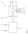
- a monitoring of the sheet travel of the sheet 15 of the Eogenoffsetdruckmaschine 1 is shown on a fan box 13.
- a video camera 16 for controlling the sheet travel of the entire sheet 15 in the horizontal direction and a video camera 17 for detecting the sheet travel of the entire sheet 15 in the vertical direction are connected to an evaluation device 18, which is designed to evaluate images of the video cameras 16,17.
- the evaluation device 18 contains an image evaluation unit 19. Depending on the output signals of the image evaluation unit 19, the fans 14 in the fan box 13 are individually controlled by the evaluation unit 18 to change the respective air flow, thus changing the position of the sheet 15 in the desired manner.
- the evaluation unit 18 is also connected to a control station 21 of the sheet-fed offset printing machine 1, which has a monitor 22 and an operating device 23.
- the evaluation unit 18 comprises an image evaluation unit 19 and a machine control device 25.
- the image evaluation unit 19 is supplied with the images recorded by the video cameras 16, 17. Via an interface 24, the image evaluation device 19 is connected to the machine control device 25.
- This machine control device 25 has a computing unit 26 which controls the printing process by evaluating signals supplied by sensors and generating control signals for actuating elements. For reasons of clarity, only one sensor for determining the machine angle 20 of the offset printing unit 3 and two fans 14 in the fan box 13 are shown here, which are connected to the machine-calculating unit 26 via an interface 27.
- FIG. 4 shows the basic structure of the image evaluation unit 19.
- the video cameras 16, 17 each have an optoelectronic CCD receiver unit, not shown in detail, which supplies an image grid with discrete pixels by means of a gray scale analysis.
- These Video information is digitized in a video interface 28 by means of an A / D converter and stored in an image memory 29 and processed in an image processing unit 30 with an arithmetic logic unit in real time.
- a D / A converter containing another video interface 31 the digital information is converted back into an analog video signal and displayed on the monitor 22 of the control station 21 of the printing machine 1.
- the ideal spatial sheet travel of a sheet 15 is stored for selected machine angles of the offset printing unit 3.
- the stored ideal sheet travel can either be determined mathematically by the image processing unit 30 for the respective desired machine angle or determined empirically from the evaluation of many actual sheet runs.
- the spatial processing unit 30 From the digitized images recorded by the video cameras 16 and 17, the spatial processing unit 30 generates a spatial image of the sheet 15 by means of the triangulation principle.
- the image processing unit 30 compares the spatial pattern of the actual sheet travel thus generated at the machine angle with an ideal spatial sheet travel stored digitally in the image memory 29 at this machine angle.
- the image evaluation unit 19 sends a corresponding signal to the machine control device 25.
- the arithmetic unit 26 evaluates the signals supplied by the image evaluation unit 19 and generates a corresponding control signal for activating the fans 14 Correct sheet travel with regard to the desired bowing by targeted air supply.
- the fans 14 are thereby controlled separately from the evaluation unit, whereby a local correction of the position of the sheet 15 is possible.
- the printer can track the sheet travel over a sheet guide path. Preferably, various locations of the entire sheet-fed offset printing machine can be monitored simultaneously.
Landscapes
- Inking, Control Or Cleaning Of Printing Machines (AREA)
- Controlling Sheets Or Webs (AREA)
- Registering, Tensioning, Guiding Webs, And Rollers Therefor (AREA)
- Control Or Security For Electrophotography (AREA)
- Investigating Materials By The Use Of Optical Means Adapted For Particular Applications (AREA)
- Printing Methods (AREA)
- Paper (AREA)
Claims (10)
- Machine d'impression (1), en particulier machine d'impression offset pour feuilles, dans laquelle une feuille (15) à traiter est guidée par des éléments de guidage de feuille (8, 9) et des dispositifs (13) pour influencer l'allure de la feuille en termes de position, un dispositif de surveillance d'allure de la feuille (16, 17) étant connecté à une unité d'analyse (18) commandant les dispositifs (13) pour influencer l'allure de la feuille, caractérisée en ce que le dispositif de surveillance d'allure de la feuille (16, 17), réalisé sous forme optique, détecte la position spatiale effective de la feuille (15) sur un élément de guidage de feuille (13) et l'unité d'analyse (18) compare la position spatiale effective de la feuille (15) avec une position spatiale idéale à l'aide d'une reconnaissance basée sur un modèle et commande, après analyse de cette comparaison au moins un dispositif (13) pour qu'il influence l'allure de la feuille (14).
- Machine d'impression selon la revendication 1, caractérisée en ce que le dispositif de surveillance d'allure de la feuille pour détecter la position spatiale de la feuille (15) est formé par deux unités d'enregistrement d'image (16, 17) dont la première unité d'enregistrement d'image (16) produit une représentation horizontale de la feuille (15) et le deuxième dispositif d'enregistrement d'image (17) produit une représentation verticale de la feuille, les deux unités d'enregistrement d'image (16, 17), pour l'analyse des représentations effectives enregistrées approximativement en même temps par elles, étant connectées à une unité d'analyse d'image (19) qui crée, à partir de ces représentations, une illustration spatiale de l'allure effective de la feuille et la compare avec l'allure spatiale idéale de la feuille mémorisée dans une unité de mémoire (29).
- Machine d'impression selon la revendication 2, caractérisée en ce que l'unité d'enregistrement d'image (16, 17) est une caméra vidéo et l'unité d'analyse d'image (19) numérise les images détectées par la caméra vidéo et les compare à une allure de feuille idéale numérisée mémorisée dans une unité de mémoire (29).
- Machine d'impression selon la revendication 2 ou 3, caractérisée en ce que l'illustration spatiale, produite par l'unité d'enregistrement d'image (16, 17), de l'allure de feuille effective, peut être acheminée à un dispositif d'affichage (22), où, en plus de l'illustration spatiale de l'allure de feuille effective, l'allure de feuille spatiale idéale associée peut être représentée en même temps.
- Machine d'impression selon la revendication 4, caractérisée en ce que l'unité d'analyse d'image (19) pour déterminer l'allure de feuille spatiale idéale est réalisée avec un auto-apprentissage.
- Machine d'impression selon la revendication 5, caractérisée en ce que l'unité d'analyse d'image (19) détermine l'allure de feuille spatiale idéale en fonction d'au moins un paramètre de machine.
- Machine d'impression selon la revendication 5, caractérisée en ce que l'unité d'analyse d'image (19) détermine l'allure de feuille spatiale idéale en fonction d'au moins un paramètre du support d'impression.
- Machine d'impression selon la revendication 2, caractérisée en ce que l'unité d'analyse d'image (19) fournit, en fonction de la comparaison, des signaux à un dispositif de commande de machine (25) pour ajuster les moyens pour influencer l'allure de la feuille (14).
- Machine d'impression selon la revendication 8, caractérisée en ce que le dispositif de commande de machine (25) est réalisé pour commander indépendamment plusieurs dispositifs pour influencer l'allure de la feuille (14).
- Machine d'impression selon la revendication 8 ou 9, caractérisée en ce que le dispositif de commande de machine (25) modifie un débit volumique des dispositifs réalisés sous forme dé composants d'air de soufflage ou d'aspiration pour influencer l'allure de la feuille (14).
Applications Claiming Priority (2)
| Application Number | Priority Date | Filing Date | Title |
|---|---|---|---|
| DE20008731U DE20008731U1 (de) | 2000-05-17 | 2000-05-17 | Druckmaschine, insbesondere Bogenoffsetdruckmaschine |
| DE20008731U | 2000-05-17 |
Publications (3)
| Publication Number | Publication Date |
|---|---|
| EP1155854A2 EP1155854A2 (fr) | 2001-11-21 |
| EP1155854A3 EP1155854A3 (fr) | 2002-12-18 |
| EP1155854B1 true EP1155854B1 (fr) | 2006-03-01 |
Family
ID=7941547
Family Applications (1)
| Application Number | Title | Priority Date | Filing Date |
|---|---|---|---|
| EP01110541A Expired - Lifetime EP1155854B1 (fr) | 2000-05-17 | 2001-04-28 | Machine d'impression, en particulier machine d'impression offset pour feuilles |
Country Status (3)
| Country | Link |
|---|---|
| EP (1) | EP1155854B1 (fr) |
| AT (1) | ATE318711T1 (fr) |
| DE (2) | DE20008731U1 (fr) |
Families Citing this family (8)
| Publication number | Priority date | Publication date | Assignee | Title |
|---|---|---|---|---|
| EP1249415A3 (fr) * | 2001-04-14 | 2004-02-04 | NexPress Solutions LLC | Procécé et dispositif pour mesurer des positions de feuilles en mouvement continu |
| DE10312162B4 (de) * | 2003-03-19 | 2009-12-10 | Koenig & Bauer Aktiengesellschaft | Verfahren und Vorrichtung zur Regelung der Bogenlage |
| DE102005056544B4 (de) * | 2004-12-21 | 2016-06-02 | Heidelberger Druckmaschinen Ag | Verfahren zur zyklischen Förderung von Bogen durch eine drucktechnische Maschine |
| JP2006175862A (ja) | 2004-12-21 | 2006-07-06 | Heidelberger Druckmas Ag | 枚葉紙を、印刷技術機械内を周期的に搬送する方法 |
| JP2009285909A (ja) * | 2008-05-28 | 2009-12-10 | Komori Corp | 両面印刷機のシート状物監視装置 |
| DE102012206926B4 (de) * | 2011-04-26 | 2025-06-12 | Koenig & Bauer Ag | Verfahren zum Ablegen von Bogen |
| DE102011100413A1 (de) * | 2011-05-04 | 2012-11-08 | Heidelberger Druckmaschinen Ag | Verfahren zur Ermittlung von Einstellfehlern in einer Bogendruckmaschine |
| DE102017208515A1 (de) * | 2017-05-19 | 2018-11-22 | Koenig & Bauer Ag | Verfahren zum Betreiben einer bogenverarbeitenden Maschine und bogenverarbeitende Maschine |
Family Cites Families (2)
| Publication number | Priority date | Publication date | Assignee | Title |
|---|---|---|---|---|
| JPS60125506A (ja) * | 1983-12-09 | 1985-07-04 | Toho Seiki Kk | 印刷物検査装置 |
| DE4217942A1 (de) * | 1992-05-30 | 1993-12-02 | Koenig & Bauer Ag | Druck-Qualitätskontrolleinrichtung für eine Schön- und Widerdruck-Rotationsdruckmaschine |
-
2000
- 2000-05-17 DE DE20008731U patent/DE20008731U1/de not_active Expired - Lifetime
-
2001
- 2001-04-28 DE DE50109030T patent/DE50109030D1/de not_active Expired - Lifetime
- 2001-04-28 EP EP01110541A patent/EP1155854B1/fr not_active Expired - Lifetime
- 2001-04-28 AT AT01110541T patent/ATE318711T1/de active
Also Published As
| Publication number | Publication date |
|---|---|
| DE50109030D1 (de) | 2006-04-27 |
| EP1155854A2 (fr) | 2001-11-21 |
| EP1155854A3 (fr) | 2002-12-18 |
| ATE318711T1 (de) | 2006-03-15 |
| DE20008731U1 (de) | 2000-08-03 |
Similar Documents
| Publication | Publication Date | Title |
|---|---|---|
| EP1620266B1 (fr) | Procédé d'utilisation de dispositifs pour r gler au moins un registre d'une presse | |
| EP0884181B1 (fr) | Procédé de regulation des operations effectuées par une machine d'impression | |
| DE102004021601B4 (de) | Inline-Messung und Regelung bei Druckmaschinen | |
| DE10214531A1 (de) | Verfahren und Einrichtung zur Messung von Positionen von durchlaufenden Bogen | |
| EP1607220B1 (fr) | Machine d'impression avec un système d'inspection en ligne | |
| EP2055483B1 (fr) | Dispositif d'affichage pour machines de traitement de supports d'impression | |
| DE102011014073A1 (de) | Verfahren zur Regelung eines Druckvorgangs | |
| DE19842192A1 (de) | Einrichtung zur Überwachung des Bogenlaufes einer bogenverarbeitenden Vorrichtung | |
| DE10261059B4 (de) | Verfahren und Vorrichtung zum Messen und Regeln eines Längs- und Seitenregisters sowie einer Druckbild-Parallelität eines Druckregisters in einer Mehrfarbendruckmaschine | |
| EP1155854A2 (fr) | Machine d'impression, en particulier machine d'impression offset pour feuilles | |
| DE19810239A1 (de) | Verfahren und Einrichtung zur Überwachung des Bogenlaufes einer bogenverarbeitenden Vorrichtung | |
| DE102017212134B4 (de) | Bogenverarbeitende Maschine | |
| DE3033780A1 (de) | Verfahren und vorrichtung zum steuern der ankunft einzeln vorgeschobener bogen aus biegsamem material | |
| DE4421199A1 (de) | Verfahren und Einrichtung zum Ausrichten von Bogen zur Förderung durch eine Druckmaschine | |
| DE102017212137B4 (de) | Bogenverarbeitende Maschine | |
| WO1994016893A1 (fr) | Dispositif permettant de determiner l'erreur de reperage entre des couleurs individuelles pendant l'impression polychrome effectuee sur une presse rotative a bande longue | |
| DE102008012588A1 (de) | Verfahren und Vorrichtung zum Messen der Farbdichte eines Farbbalkens in einer Druckmaschine, und Druckmaschine, die mit einer Farbdichte-Messvorrichtung ausgestattet ist | |
| DE102017212138B4 (de) | Bogenverarbeitende Maschine | |
| EP1156382B1 (fr) | Méthode et appareil pour l'ajustement de registre dans une imprimante couleur | |
| DE102017012187B4 (de) | Bogenverarbeitende Maschine | |
| DE102017212133B4 (de) | Bogenverarbeitende Maschine und Verfahren zum Betreiben einer bogenverarbeitenden Maschine | |
| DE102017212140B4 (de) | Bogenverarbeitende Maschine | |
| DE102017212143B4 (de) | Bogenverarbeitende Maschine | |
| DE102017212132B4 (de) | Bogenverarbeitende Maschine | |
| DE102017212141B4 (de) | Bogenverarbeitende Maschine |
Legal Events
| Date | Code | Title | Description |
|---|---|---|---|
| PUAI | Public reference made under article 153(3) epc to a published international application that has entered the european phase |
Free format text: ORIGINAL CODE: 0009012 |
|
| AK | Designated contracting states |
Kind code of ref document: A2 Designated state(s): AT BE CH CY DE DK ES FI FR GB GR IE IT LI LU MC NL PT SE TR |
|
| AX | Request for extension of the european patent |
Free format text: AL;LT;LV;MK;RO;SI |
|
| PUAL | Search report despatched |
Free format text: ORIGINAL CODE: 0009013 |
|
| AK | Designated contracting states |
Kind code of ref document: A3 Designated state(s): AT BE CH CY DE DK ES FI FR GB GR IE IT LI LU MC NL PT SE TR |
|
| AX | Request for extension of the european patent |
Free format text: AL;LT;LV;MK;RO;SI |
|
| 17P | Request for examination filed |
Effective date: 20021115 |
|
| AKX | Designation fees paid |
Designated state(s): AT BE CH CY DE DK ES FI FR GB GR IE IT LI LU MC NL PT SE TR |
|
| GRAP | Despatch of communication of intention to grant a patent |
Free format text: ORIGINAL CODE: EPIDOSNIGR1 |
|
| GRAS | Grant fee paid |
Free format text: ORIGINAL CODE: EPIDOSNIGR3 |
|
| GRAA | (expected) grant |
Free format text: ORIGINAL CODE: 0009210 |
|
| AK | Designated contracting states |
Kind code of ref document: B1 Designated state(s): AT BE CH CY DE DK ES FI FR GB GR IE IT LI LU MC NL PT SE TR |
|
| PG25 | Lapsed in a contracting state [announced via postgrant information from national office to epo] |
Ref country code: IT Free format text: LAPSE BECAUSE OF FAILURE TO SUBMIT A TRANSLATION OF THE DESCRIPTION OR TO PAY THE FEE WITHIN THE PRESCRIBED TIME-LIMIT;WARNING: LAPSES OF ITALIAN PATENTS WITH EFFECTIVE DATE BEFORE 2007 MAY HAVE OCCURRED AT ANY TIME BEFORE 2007. THE CORRECT EFFECTIVE DATE MAY BE DIFFERENT FROM THE ONE RECORDED. Effective date: 20060301 Ref country code: FI Free format text: LAPSE BECAUSE OF FAILURE TO SUBMIT A TRANSLATION OF THE DESCRIPTION OR TO PAY THE FEE WITHIN THE PRESCRIBED TIME-LIMIT Effective date: 20060301 Ref country code: IE Free format text: LAPSE BECAUSE OF FAILURE TO SUBMIT A TRANSLATION OF THE DESCRIPTION OR TO PAY THE FEE WITHIN THE PRESCRIBED TIME-LIMIT Effective date: 20060301 Ref country code: GB Free format text: LAPSE BECAUSE OF FAILURE TO SUBMIT A TRANSLATION OF THE DESCRIPTION OR TO PAY THE FEE WITHIN THE PRESCRIBED TIME-LIMIT Effective date: 20060301 Ref country code: NL Free format text: LAPSE BECAUSE OF FAILURE TO SUBMIT A TRANSLATION OF THE DESCRIPTION OR TO PAY THE FEE WITHIN THE PRESCRIBED TIME-LIMIT Effective date: 20060301 |
|
| REG | Reference to a national code |
Ref country code: GB Ref legal event code: FG4D Free format text: NOT ENGLISH |
|
| REG | Reference to a national code |
Ref country code: CH Ref legal event code: EP |
|
| REG | Reference to a national code |
Ref country code: IE Ref legal event code: FG4D Free format text: LANGUAGE OF EP DOCUMENT: GERMAN |
|
| REF | Corresponds to: |
Ref document number: 50109030 Country of ref document: DE Date of ref document: 20060427 Kind code of ref document: P |
|
| PG25 | Lapsed in a contracting state [announced via postgrant information from national office to epo] |
Ref country code: LI Free format text: LAPSE BECAUSE OF NON-PAYMENT OF DUE FEES Effective date: 20060430 Ref country code: MC Free format text: LAPSE BECAUSE OF NON-PAYMENT OF DUE FEES Effective date: 20060430 Ref country code: BE Free format text: LAPSE BECAUSE OF NON-PAYMENT OF DUE FEES Effective date: 20060430 Ref country code: CH Free format text: LAPSE BECAUSE OF NON-PAYMENT OF DUE FEES Effective date: 20060430 |
|
| PG25 | Lapsed in a contracting state [announced via postgrant information from national office to epo] |
Ref country code: SE Free format text: LAPSE BECAUSE OF FAILURE TO SUBMIT A TRANSLATION OF THE DESCRIPTION OR TO PAY THE FEE WITHIN THE PRESCRIBED TIME-LIMIT Effective date: 20060601 Ref country code: DK Free format text: LAPSE BECAUSE OF FAILURE TO SUBMIT A TRANSLATION OF THE DESCRIPTION OR TO PAY THE FEE WITHIN THE PRESCRIBED TIME-LIMIT Effective date: 20060601 |
|
| PG25 | Lapsed in a contracting state [announced via postgrant information from national office to epo] |
Ref country code: ES Free format text: LAPSE BECAUSE OF FAILURE TO SUBMIT A TRANSLATION OF THE DESCRIPTION OR TO PAY THE FEE WITHIN THE PRESCRIBED TIME-LIMIT Effective date: 20060612 |
|
| PG25 | Lapsed in a contracting state [announced via postgrant information from national office to epo] |
Ref country code: PT Free format text: LAPSE BECAUSE OF FAILURE TO SUBMIT A TRANSLATION OF THE DESCRIPTION OR TO PAY THE FEE WITHIN THE PRESCRIBED TIME-LIMIT Effective date: 20060801 |
|
| NLV1 | Nl: lapsed or annulled due to failure to fulfill the requirements of art. 29p and 29m of the patents act | ||
| GBV | Gb: ep patent (uk) treated as always having been void in accordance with gb section 77(7)/1977 [no translation filed] |
Effective date: 20060301 |
|
| REG | Reference to a national code |
Ref country code: IE Ref legal event code: FD4D |
|
| REG | Reference to a national code |
Ref country code: CH Ref legal event code: PL |
|
| PLBE | No opposition filed within time limit |
Free format text: ORIGINAL CODE: 0009261 |
|
| STAA | Information on the status of an ep patent application or granted ep patent |
Free format text: STATUS: NO OPPOSITION FILED WITHIN TIME LIMIT |
|
| 26N | No opposition filed |
Effective date: 20061204 |
|
| EN | Fr: translation not filed | ||
| BERE | Be: lapsed |
Owner name: MAN ROLAND DRUCKMASCHINEN A.G. Effective date: 20060430 |
|
| PG25 | Lapsed in a contracting state [announced via postgrant information from national office to epo] |
Ref country code: GR Free format text: LAPSE BECAUSE OF FAILURE TO SUBMIT A TRANSLATION OF THE DESCRIPTION OR TO PAY THE FEE WITHIN THE PRESCRIBED TIME-LIMIT Effective date: 20060602 |
|
| PG25 | Lapsed in a contracting state [announced via postgrant information from national office to epo] |
Ref country code: LU Free format text: LAPSE BECAUSE OF NON-PAYMENT OF DUE FEES Effective date: 20060428 Ref country code: TR Free format text: LAPSE BECAUSE OF FAILURE TO SUBMIT A TRANSLATION OF THE DESCRIPTION OR TO PAY THE FEE WITHIN THE PRESCRIBED TIME-LIMIT Effective date: 20060301 |
|
| PG25 | Lapsed in a contracting state [announced via postgrant information from national office to epo] |
Ref country code: CY Free format text: LAPSE BECAUSE OF FAILURE TO SUBMIT A TRANSLATION OF THE DESCRIPTION OR TO PAY THE FEE WITHIN THE PRESCRIBED TIME-LIMIT Effective date: 20060301 Ref country code: FR Free format text: LAPSE BECAUSE OF FAILURE TO SUBMIT A TRANSLATION OF THE DESCRIPTION OR TO PAY THE FEE WITHIN THE PRESCRIBED TIME-LIMIT Effective date: 20060301 |
|
| PGFP | Annual fee paid to national office [announced via postgrant information from national office to epo] |
Ref country code: AT Payment date: 20110414 Year of fee payment: 11 |
|
| REG | Reference to a national code |
Ref country code: DE Ref legal event code: R081 Ref document number: 50109030 Country of ref document: DE Owner name: MANROLAND SHEETFED GMBH, DE Free format text: FORMER OWNER: MANROLAND AG, 63075 OFFENBACH, DE Effective date: 20120509 |
|
| REG | Reference to a national code |
Ref country code: AT Ref legal event code: MM01 Ref document number: 318711 Country of ref document: AT Kind code of ref document: T Effective date: 20120428 |
|
| PG25 | Lapsed in a contracting state [announced via postgrant information from national office to epo] |
Ref country code: AT Free format text: LAPSE BECAUSE OF NON-PAYMENT OF DUE FEES Effective date: 20120428 |
|
| PGFP | Annual fee paid to national office [announced via postgrant information from national office to epo] |
Ref country code: DE Payment date: 20140418 Year of fee payment: 14 |
|
| REG | Reference to a national code |
Ref country code: DE Ref legal event code: R119 Ref document number: 50109030 Country of ref document: DE |
|
| PG25 | Lapsed in a contracting state [announced via postgrant information from national office to epo] |
Ref country code: DE Free format text: LAPSE BECAUSE OF NON-PAYMENT OF DUE FEES Effective date: 20151103 |