EP1155907A2 - Unité d'éclairage de véhicule - Google Patents
Unité d'éclairage de véhicule Download PDFInfo
- Publication number
- EP1155907A2 EP1155907A2 EP01110216A EP01110216A EP1155907A2 EP 1155907 A2 EP1155907 A2 EP 1155907A2 EP 01110216 A EP01110216 A EP 01110216A EP 01110216 A EP01110216 A EP 01110216A EP 1155907 A2 EP1155907 A2 EP 1155907A2
- Authority
- EP
- European Patent Office
- Prior art keywords
- motor vehicle
- vehicle according
- lamp housing
- end wall
- counter surface
- Prior art date
- Legal status (The legal status is an assumption and is not a legal conclusion. Google has not performed a legal analysis and makes no representation as to the accuracy of the status listed.)
- Granted
Links
- 239000004417 polycarbonate Substances 0.000 claims description 3
- 229920000515 polycarbonate Polymers 0.000 claims description 3
- 238000004904 shortening Methods 0.000 claims description 3
- 239000011521 glass Substances 0.000 abstract 1
- 238000010276 construction Methods 0.000 description 4
- 238000010521 absorption reaction Methods 0.000 description 2
- 238000005253 cladding Methods 0.000 description 2
- 238000009826 distribution Methods 0.000 description 2
- 238000009434 installation Methods 0.000 description 2
- 239000006096 absorbing agent Substances 0.000 description 1
- 229910052782 aluminium Inorganic materials 0.000 description 1
- XAGFODPZIPBFFR-UHFFFAOYSA-N aluminium Chemical compound [Al] XAGFODPZIPBFFR-UHFFFAOYSA-N 0.000 description 1
- 239000004918 carbon fiber reinforced polymer Substances 0.000 description 1
- 239000003795 chemical substances by application Substances 0.000 description 1
- 239000002131 composite material Substances 0.000 description 1
- 238000006073 displacement reaction Methods 0.000 description 1
- 230000002349 favourable effect Effects 0.000 description 1
- 239000000835 fiber Substances 0.000 description 1
- 239000000834 fixative Substances 0.000 description 1
- 238000012423 maintenance Methods 0.000 description 1
- 238000004519 manufacturing process Methods 0.000 description 1
- 239000000463 material Substances 0.000 description 1
- 230000013011 mating Effects 0.000 description 1
- 229910001092 metal group alloy Inorganic materials 0.000 description 1
- 238000005192 partition Methods 0.000 description 1
- 239000004033 plastic Substances 0.000 description 1
- 230000007704 transition Effects 0.000 description 1
- 238000009827 uniform distribution Methods 0.000 description 1
- 239000002023 wood Substances 0.000 description 1
Images



Classifications
-
- B—PERFORMING OPERATIONS; TRANSPORTING
- B60—VEHICLES IN GENERAL
- B60Q—ARRANGEMENT OF SIGNALLING OR LIGHTING DEVICES, THE MOUNTING OR SUPPORTING THEREOF OR CIRCUITS THEREFOR, FOR VEHICLES IN GENERAL
- B60Q1/00—Arrangement of optical signalling or lighting devices, the mounting or supporting thereof or circuits therefor
- B60Q1/02—Arrangement of optical signalling or lighting devices, the mounting or supporting thereof or circuits therefor the devices being primarily intended to illuminate the way ahead or to illuminate other areas of way or environments
- B60Q1/04—Arrangement of optical signalling or lighting devices, the mounting or supporting thereof or circuits therefor the devices being primarily intended to illuminate the way ahead or to illuminate other areas of way or environments the devices being headlights
- B60Q1/0408—Arrangement of optical signalling or lighting devices, the mounting or supporting thereof or circuits therefor the devices being primarily intended to illuminate the way ahead or to illuminate other areas of way or environments the devices being headlights built into the vehicle body, e.g. details concerning the mounting of the headlamps on the vehicle body
- B60Q1/0416—Arrangement of optical signalling or lighting devices, the mounting or supporting thereof or circuits therefor the devices being primarily intended to illuminate the way ahead or to illuminate other areas of way or environments the devices being headlights built into the vehicle body, e.g. details concerning the mounting of the headlamps on the vehicle body the housing being mounted on the vehicle body using rails
-
- B—PERFORMING OPERATIONS; TRANSPORTING
- B60—VEHICLES IN GENERAL
- B60Q—ARRANGEMENT OF SIGNALLING OR LIGHTING DEVICES, THE MOUNTING OR SUPPORTING THEREOF OR CIRCUITS THEREFOR, FOR VEHICLES IN GENERAL
- B60Q1/00—Arrangement of optical signalling or lighting devices, the mounting or supporting thereof or circuits therefor
- B60Q1/02—Arrangement of optical signalling or lighting devices, the mounting or supporting thereof or circuits therefor the devices being primarily intended to illuminate the way ahead or to illuminate other areas of way or environments
- B60Q1/04—Arrangement of optical signalling or lighting devices, the mounting or supporting thereof or circuits therefor the devices being primarily intended to illuminate the way ahead or to illuminate other areas of way or environments the devices being headlights
- B60Q1/0491—Shock absorbing devices therefor
Definitions
- the invention relates to a motor vehicle with a Lighting unit according to the preamble of claim 1.
- a motor vehicle is provided, at the front end of a vehicle support structure is arranged.
- a reflector with one translucent pane and a lamp housing a Unit, from a tubular, the unit circumferential enclosing and energy absorbing Deformation member is added.
- the unit is in axial direction in the tubular deformation member can be inserted and secured in the installed position.
- the Deformation member is axially supported on a wheel arch wall and collapses with shortening in the case of excessive Impact load.
- the known arrangement expensive and has a relatively high weight.
- the invention is therefore based on the object To create a motor vehicle with a light unit, the can be significantly simpler and less expensive is to be produced.
- the lamp housing is present anyway trained as an energy absorbing deformation member, the savings on components a simplified and enables inexpensive construction of the lighting unit. It can the arrangement with light unit can be exchanged in a simple manner be designed so that with light or medium Impact loads only the housing of the lighting unit deformed and then in a relatively inexpensive way can be exchanged.
- the counter surface of the support structure in a largely vertical vehicle transverse plane is arranged and approximately parallel runs to the rear end of the lamp housing, can a particularly effective support of the lamp housing on the Support structure to be created.
- a disk made of impact-resistant has proven to be particularly advantageous Polycarbonate shown along its circumference uniform distribution of the occurring accident forces the outward facing end of the lamp housing connected is.
- the counter surface is preferred as a region of an end wall formed the minor damage area of the support structure from the crumple zone behind for more serious accidents separates. It can be in front of the end wall Components such as the lighting units deformed in an accident without the underlying structure already Undergoes deformations.
- the arrangement is particularly easy to change using an in Slidable luminaire housing guides in the inserted installation position by fixative in its final position is to be determined.
- Figure 1 is a perspective view obliquely from the top front predominantly energy absorbing, inherently stiff and level Supporting structure of a motor vehicle with lightweight building boards shown.
- the lightweight panels are preferably depending on Requirement in sandwich construction, with honeycomb structure, in wood, in Aluminum, as a fiber composite, as an extruded profile or the like. manufactured. To achieve favorable manufacturing conditions, can the individual plate sections both in one piece be trained and angled as well as assembled in several parts.
- a load-bearing floor 10 goes into a Front wall 14 in lightweight construction, which one to the floor 10 subsequent transition area 16 and an approximately vertical Area 18 includes.
- the footwell area 12 is at the side and at the top bounded by a plate arrangement, the front and one rear upper lightweight board 26.28 and side Support box walls 30, which together with the floor 10 and the end wall 14 a support box 22 for one on this form attached stem structure 24.
- the stem structure 24 designed as a crumple zone comprises two front side members 34, each an angled Cross section with an approximately vertical plate leg 36 and have a transverse plate leg 38.
- At the front end of the longitudinal beam 34 is an in Vehicle transverse direction and approximately vertically running front End wall 42 attached, here from an extruded profile consists.
- the lightweight board 42 can be in one piece as well - As shown here - be formed in several parts.
- the floor 10 goes obliquely backwards upwards protruding rear partition 52, behind which is a Crumple zone formed rear structure 54 with rear Side members 56 connects. These each have an in Vehicle vertical direction and one in the vehicle longitudinal direction angled plate leg 58.60. At the back of the rear side member 56 is a rear end wall 64 attached that in the vehicle transverse direction and approximately vertically runs.
- the rear side members 56 are over a Panel arrangement made of lightweight panels 74,75,76 firmly together connected to a box.
- One located between the front and rear end wall 42,64 extending side wall 32 has a door cutout 78 for a side door 80 (FIG. 2), from which is only shown here a left door inner wall 82.
- the support structure shown in Figure 2 in perspective view Fig.1 is arranged under a planking, from here on corresponding recordings of the supporting structure Trim parts 88 of the right front and rear Fender are shown.
- At the front of the front End wall 42 also shows a front module 50, which one over two longitudinal legs 96 on the lightweight board 42 includes fixed cross member 94.
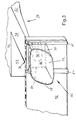
- FIG. 3 shows a schematic perspective view of sections the front, attached in the area of the front side member 34 End wall 42, on the front of which a lighting unit 66 is arranged.
- the lamp unit 66 comprises a lamp housing 70, which the extent of an associated, in Figures 4 and 5 schematically indicated reflector 68 encloses and as energy-absorbing deformation member is formed.
- the Luminaire housing 70 is preferably made of one energy absorbing plastic such as CFRP or FRP or one Made of metal alloy. How the Luminaire unit with an excessive impact load is in the further discussed in more detail.
- the reflector 68 and that this receiving lamp housing 70 form with a translucent disc 72 a unit.
- Disc 72 is made of polycarbonate and along its circumference power distribution with the forward facing, dashed indicated end face 78 of the lamp housing 70 connected. Accordingly, the lamp housing 70 with its front End face 78 adapted to the circumference of the disk 72.
- the one in front area adapted to the disc 72 cross section of the Luminaire housing 70 goes in the direction of the dashed line indicated rear end 80 in an approximately rectangular cross section over. With this roughly rectangular the rear end 80 supports the lamp housing 70 excessive impact load axially on a mating surface 82 of the front end wall 42 from shortening the length.
- the Counter surface 82 runs here as a flat area of the End wall 42 in a vertical vehicle transverse plane, on the the rear end face 80 of the lamp housing 70 already supports in the installation position.
- the rear end face 80 in the installed position ends at a distance from the counter surface 82 and only as a result an accident-related shift in the direction of the end wall 42 is supported on this.
- the rear extends End face 80 preferably approximately parallel to counter surface 82, so that the lamp housing 70 in its accident-related Displacement with the rear face 80 can support power distribution on the counter surface 82.
- the counter surface 82 in a surface inclined to the end wall 42 is arranged.
- this vertical sliding guides 84,85 provided in the the lamp housing 70 with its rear area is inserted.
- the two sliding guides 84, 85 are here L-shaped in cross-section and in one piece with the Extruded profile of the end wall 42 is formed.
- the counter surface 82 lies here approximately in the coverage area with the associated end of the Side member 34.
- FIG 4 is a schematic, partial plan view carried by the front end of the left side member 35 front end wall 42 and the attached to this Luminous unit 66 shown in Figure 3, in particular the one-piece design of the sliding guides 84, 85 and End wall 42 can be seen.
- the lamp housing 70 On his roughly right-angled one rear area is the lamp housing 70 with vertical provided guide rails 86,87, which are about extend the entire height of the lamp housing 70 and with which the lamp housing 70 in the sliding guides 84.85 can be inserted.
- the lamp unit 66 here via screw connections 88 on the End wall 42 fixed.
- Fixing agents such as tabs, strips or the like are conceivable.
- the planar support of the lamp housing 70 on the counter surface 82 has the advantage that the fixing means themselves do not Impact forces take over and therefore do not attach themselves Crash aspects must be oriented.
- the sliding guides 84.85 to be arranged horizontally and accordingly the lighting unit 66 slide horizontally.
- an oblique arrangement of the Sliding guides 84.85 would be possible.
- a Light source 99 indicated by dashed lines, which here over a Assembly and maintenance opening 98 (FIG. 3) in the end wall 42 is accessible from behind.
- the cables 100 of the light source 99 can be guided through this opening 98, the Luminaire housing 70 is open at the rear.
- the sliding guides 84, 85 in combination with the Last 86.87 to power the light source 98 as Use busbars.
- Fig. 5 is a schematic, perspective side view of the front end wall 42 and the light unit 66 attached thereto according to FIGS. 3 and 4 shown. It can be seen that the disc 72 to the dashed bow contour of the vehicle is adjusted. They are the supporting structure in the area of the lighting unit cladding paneling parts 88 (Fig.2) so that the respective luminaire housing 70 into the sliding guides 84, 85 can be inserted. Of course it would also be conceivable that Luminaire housing 70 via a plug connection, for example by attaching axially to the end wall 42.
- the lighting unit 66 can of course also on the rear End wall 64 as a rear light unit, or the side of Support structure as a turn signal light unit on load-bearing components be attached to the supporting structure. Instead of here described support structure made of flat lightweight boards of course, a support structure in a usual today Body shell or frame construction can be used.
- the light unit 66 can also other units, in particular the front module 50 or a similar rear module via further sliding guides on the assigned end wall 42.64 must be set.
- the further units 50 can also via a housing designed as a deformation part feature.
- the support structure preferably has a deformation sequence in which the front module 50 is first deformed with the cross member 94 and the longitudinal legs 96.
- the energy-absorbing lighting unit 66 and possibly further modules arranged in front of the end wall 42 are then acted on before the front structure 24 with the front longitudinal members 34 is then used for further absorption of the accident energy.
- the shape of the safety passenger compartment remains largely intact even in the event of a major accident.
- the front end wall 42 separates the minor damage area of the support structure from the crumple area for more serious accidents, ie the components in front of the end wall 42, such as the lighting units 66, can be deformed in the event of a frontal impact without the structure behind them already undergoing deformation.
- the lighting unit 66 becomes an effective energy absorber, which protects the underlying support structure, which can often only be repaired at great expense, at least in the range of low to medium accident severities.
- the lighting unit 66 is deformed by being squeezed between the obstacle and the structural wall.
- the energy absorption capacity of the entire lamp unit 66 can be influenced by the choice of material and the wall thickness dimensioning of the lamp housing 70, or by ribbing of the housing wall.
- the rear structure 54 is preferably also formed.
Landscapes
- Engineering & Computer Science (AREA)
- Mechanical Engineering (AREA)
- Lighting Device Outwards From Vehicle And Optical Signal (AREA)
- Motor Or Generator Frames (AREA)
- Non-Portable Lighting Devices Or Systems Thereof (AREA)
Applications Claiming Priority (2)
| Application Number | Priority Date | Filing Date | Title |
|---|---|---|---|
| DE10023570A DE10023570C2 (de) | 2000-05-15 | 2000-05-15 | Kraftfahrzeug mit einer Leuchteinheit |
| DE10023570 | 2000-05-15 |
Publications (3)
| Publication Number | Publication Date |
|---|---|
| EP1155907A2 true EP1155907A2 (fr) | 2001-11-21 |
| EP1155907A3 EP1155907A3 (fr) | 2003-11-19 |
| EP1155907B1 EP1155907B1 (fr) | 2006-03-29 |
Family
ID=7641982
Family Applications (1)
| Application Number | Title | Priority Date | Filing Date |
|---|---|---|---|
| EP01110216A Expired - Lifetime EP1155907B1 (fr) | 2000-05-15 | 2001-04-25 | Unité d'éclairage de véhicule |
Country Status (4)
| Country | Link |
|---|---|
| US (1) | US6652131B2 (fr) |
| EP (1) | EP1155907B1 (fr) |
| DE (2) | DE10023570C2 (fr) |
| ES (1) | ES2260116T3 (fr) |
Cited By (3)
| Publication number | Priority date | Publication date | Assignee | Title |
|---|---|---|---|---|
| EP1400405A1 (fr) * | 2002-09-20 | 2004-03-24 | Valeo Vision | Projecteur comportant des moyens d'absorption d'énergie |
| FR2887197A1 (fr) * | 2005-06-21 | 2006-12-22 | Peugeot Citroen Automobiles Sa | Projecteur de vehicule automobile comportant une glace adapt ee pour se rompre en cas de choc |
| WO2019058039A1 (fr) * | 2017-09-25 | 2019-03-28 | Psa Automobiles Sa | Piece de fixation pour un projecteur de vehicule automobile |
Families Citing this family (4)
| Publication number | Priority date | Publication date | Assignee | Title |
|---|---|---|---|---|
| DE10352903B4 (de) * | 2003-11-11 | 2015-06-18 | Hbpo Gmbh | Leuchteinheit für Fahrzeuge |
| DE102004054020A1 (de) * | 2004-11-05 | 2006-05-18 | Peguform Gmbh | Scheinwerfergehäuse |
| DE102009016941B4 (de) * | 2009-04-08 | 2017-10-19 | Daimler Ag | Energieabsorptionseinrichtung |
| US10827247B2 (en) * | 2019-01-07 | 2020-11-03 | Bose Corporation | Earphone |
Citations (1)
| Publication number | Priority date | Publication date | Assignee | Title |
|---|---|---|---|---|
| DE19732301A1 (de) | 1996-08-22 | 1998-02-26 | Volkswagen Ag | Scheinwerferanordnung für ein Kraftfahrzeug |
Family Cites Families (14)
| Publication number | Priority date | Publication date | Assignee | Title |
|---|---|---|---|---|
| DE2446207C3 (de) * | 1974-09-27 | 1979-05-23 | Ford-Werke Ag, 5000 Koeln | Stoßstangen-Eckstück für Kraftfahrzeuge |
| DE2732895C3 (de) * | 1977-07-21 | 1981-09-10 | Ford-Werke Ag, 5000 Koeln | Scheinwerfer, insbesondere für Kraftfahrzeuge |
| US4270787A (en) * | 1980-03-03 | 1981-06-02 | Ford Motor Company | Displaceable lamp |
| US4466646A (en) * | 1983-02-25 | 1984-08-21 | General Motors Corporation | Energy absorbing bumper assembly for vehicles |
| FR2615156B1 (fr) * | 1987-05-13 | 1989-08-18 | Peugeot Aciers Et Outillage | Structure modulaire pour vehicule et son application a l'assemblage automatique de celui-ci |
| FR2677943B1 (fr) * | 1991-06-19 | 1993-10-22 | Ecia | Facade anterieure perfectionnee pour vehicules automobiles. |
| JP3591037B2 (ja) * | 1995-03-30 | 2004-11-17 | 日産自動車株式会社 | 自動車のランプ取付構造 |
| US5819408A (en) * | 1996-07-10 | 1998-10-13 | Xcorp, Inc. | Recyclable, low cost, collision-resistant automobile chassis and body |
| DE19850106A1 (de) * | 1998-11-02 | 2000-05-04 | Hella Kg Hueck & Co | Scheinwerfer und Verfahren zur Montage |
| FR2785242B1 (fr) * | 1998-11-02 | 2001-01-26 | Peugeot | Feu arriere de vehicules automobiles |
| FR2789028B1 (fr) * | 1999-02-02 | 2001-04-27 | Peugeot Citroen Automobiles Sa | Boitier pour projecteur ou analogue |
| US6190030B1 (en) * | 1999-02-18 | 2001-02-20 | Lacks Industries, Inc. | Flexible lamp mounting |
| DE19955648C2 (de) * | 1999-11-19 | 2001-10-31 | Audi Ag | Scheinwerferanordnung |
| JP4345041B2 (ja) * | 2000-02-07 | 2009-10-14 | マツダ株式会社 | 車両用灯具 |
-
2000
- 2000-05-15 DE DE10023570A patent/DE10023570C2/de not_active Expired - Fee Related
-
2001
- 2001-04-25 ES ES01110216T patent/ES2260116T3/es not_active Expired - Lifetime
- 2001-04-25 EP EP01110216A patent/EP1155907B1/fr not_active Expired - Lifetime
- 2001-04-25 DE DE50109348T patent/DE50109348D1/de not_active Expired - Fee Related
- 2001-05-15 US US09/854,910 patent/US6652131B2/en not_active Expired - Fee Related
Patent Citations (1)
| Publication number | Priority date | Publication date | Assignee | Title |
|---|---|---|---|---|
| DE19732301A1 (de) | 1996-08-22 | 1998-02-26 | Volkswagen Ag | Scheinwerferanordnung für ein Kraftfahrzeug |
Cited By (8)
| Publication number | Priority date | Publication date | Assignee | Title |
|---|---|---|---|---|
| EP1400405A1 (fr) * | 2002-09-20 | 2004-03-24 | Valeo Vision | Projecteur comportant des moyens d'absorption d'énergie |
| FR2844758A1 (fr) * | 2002-09-20 | 2004-03-26 | Valeo Vision | Projecteur de vehicule automobile comportant des moyens d'absorption d'energie |
| US7156545B2 (en) | 2002-09-20 | 2007-01-02 | Valeo Vision | Headlamp comprising energy absorption means |
| US7419291B2 (en) | 2002-09-20 | 2008-09-02 | Valeo Vision | Headlamp comprising energy absorption means |
| FR2887197A1 (fr) * | 2005-06-21 | 2006-12-22 | Peugeot Citroen Automobiles Sa | Projecteur de vehicule automobile comportant une glace adapt ee pour se rompre en cas de choc |
| EP1736358A1 (fr) * | 2005-06-21 | 2006-12-27 | Peugeot Citroen Automobiles SA | Projecteur de véhicule automobile |
| WO2019058039A1 (fr) * | 2017-09-25 | 2019-03-28 | Psa Automobiles Sa | Piece de fixation pour un projecteur de vehicule automobile |
| FR3071457A1 (fr) * | 2017-09-25 | 2019-03-29 | Psa Automobiles Sa | Piece de fixation pour un projecteur de vehicule automobile |
Also Published As
| Publication number | Publication date |
|---|---|
| EP1155907A3 (fr) | 2003-11-19 |
| US6652131B2 (en) | 2003-11-25 |
| DE50109348D1 (de) | 2006-05-18 |
| EP1155907B1 (fr) | 2006-03-29 |
| ES2260116T3 (es) | 2006-11-01 |
| DE10023570C2 (de) | 2002-03-14 |
| US20020008977A1 (en) | 2002-01-24 |
| DE10023570A1 (de) | 2001-11-22 |
Similar Documents
| Publication | Publication Date | Title |
|---|---|---|
| DE69709609T2 (de) | Trägerelement für Karrosserieteil | |
| DE4326270C2 (de) | Kraftfahrzeug mit einer steifen Bodenstruktur | |
| EP1000840B1 (fr) | Structure de suppport de la partie avant pour un véhicule automobile | |
| DE3302564A1 (de) | Rahmenaufbau fuer ein viersitziges personenkraftfahrzeug | |
| DE19917177A1 (de) | Tragstruktur für Kraftwagen | |
| EP0874176A2 (fr) | Elément pour l'absorption d'énergie | |
| WO2004024543A1 (fr) | Carrosserie de voiture a structure portante composee de modules de grandes dimensions | |
| DE69313214T2 (de) | Struktur zur Energieaufnahme, insbesondere für Eisenbahnfahrzeuge | |
| DE3035333A1 (de) | Personenkraftwagen | |
| WO1992011161A1 (fr) | Carrosserie pour voiture de tourisme | |
| DE8815885U1 (de) | Fahrzeugkarosserie | |
| DE19603954A1 (de) | Prallträger für ein Kraftfahrzeug und Verfahren zu seiner Herstellung | |
| DE2619173A1 (de) | Als geschlossener hohltraeger ausgebildeter vorderer laengstraeger | |
| DE602005004442T2 (de) | Verfahren zur Erstellung einer Trägerplatte einer energieabsorbierenden Stossstange und durch dieses Verfahren erhaltene Trägerplatte | |
| DE19746238A1 (de) | Karosserieaufbau eines Personenkraftwagens | |
| DE10023570C2 (de) | Kraftfahrzeug mit einer Leuchteinheit | |
| DE102012213019B4 (de) | Zugkopfteil | |
| DE102006009290B4 (de) | Tragstruktur für ein Frontend eines Kraftwagens | |
| DE10032663B4 (de) | Kraftwagen mit einer selbsttragenden Karosserie | |
| DE60212258T2 (de) | Schutzkonstruktion für Fahrzeuge | |
| DE10023112A1 (de) | Fahrzeugkarosserie | |
| DE10018900B4 (de) | Kraftwagen mit einer Tragstruktur | |
| DE69714465T2 (de) | Omnibus mit sicherheitsvorrichtungen wie eine überrollvorrichtung, sowie verfahren zum zusammenbau eines omnibuses | |
| AT414118B (de) | Modul einer sicherheitszelle für verkehrs- und transportmittel | |
| EP1155895B1 (fr) | Arrangement d'échangeur de chaleur sur une structure de support avant d'une automobile |
Legal Events
| Date | Code | Title | Description |
|---|---|---|---|
| PUAI | Public reference made under article 153(3) epc to a published international application that has entered the european phase |
Free format text: ORIGINAL CODE: 0009012 |
|
| AK | Designated contracting states |
Kind code of ref document: A2 Designated state(s): AT BE CH CY DE DK ES FI FR GB GR IE IT LI LU MC NL PT SE TR |
|
| AX | Request for extension of the european patent |
Free format text: AL;LT;LV;MK;RO;SI |
|
| PUAL | Search report despatched |
Free format text: ORIGINAL CODE: 0009013 |
|
| AK | Designated contracting states |
Kind code of ref document: A3 Designated state(s): AT BE CH CY DE DK ES FI FR GB GR IE IT LI LU MC NL PT SE TR |
|
| AX | Request for extension of the european patent |
Extension state: AL LT LV MK RO SI |
|
| 17P | Request for examination filed |
Effective date: 20031015 |
|
| 17Q | First examination report despatched |
Effective date: 20040126 |
|
| AKX | Designation fees paid |
Designated state(s): DE ES FR GB IT |
|
| GRAP | Despatch of communication of intention to grant a patent |
Free format text: ORIGINAL CODE: EPIDOSNIGR1 |
|
| GRAS | Grant fee paid |
Free format text: ORIGINAL CODE: EPIDOSNIGR3 |
|
| GRAA | (expected) grant |
Free format text: ORIGINAL CODE: 0009210 |
|
| AK | Designated contracting states |
Kind code of ref document: B1 Designated state(s): DE ES FR GB IT |
|
| REG | Reference to a national code |
Ref country code: GB Ref legal event code: FG4D Free format text: NOT ENGLISH |
|
| PGFP | Annual fee paid to national office [announced via postgrant information from national office to epo] |
Ref country code: FR Payment date: 20060411 Year of fee payment: 6 |
|
| GBT | Gb: translation of ep patent filed (gb section 77(6)(a)/1977) |
Effective date: 20060329 |
|
| PGFP | Annual fee paid to national office [announced via postgrant information from national office to epo] |
Ref country code: DE Payment date: 20060419 Year of fee payment: 6 |
|
| PGFP | Annual fee paid to national office [announced via postgrant information from national office to epo] |
Ref country code: GB Payment date: 20060420 Year of fee payment: 6 |
|
| PGFP | Annual fee paid to national office [announced via postgrant information from national office to epo] |
Ref country code: ES Payment date: 20060427 Year of fee payment: 6 |
|
| PGFP | Annual fee paid to national office [announced via postgrant information from national office to epo] |
Ref country code: IT Payment date: 20060430 Year of fee payment: 6 |
|
| REF | Corresponds to: |
Ref document number: 50109348 Country of ref document: DE Date of ref document: 20060518 Kind code of ref document: P |
|
| REG | Reference to a national code |
Ref country code: ES Ref legal event code: FG2A Ref document number: 2260116 Country of ref document: ES Kind code of ref document: T3 |
|
| ET | Fr: translation filed | ||
| PLBE | No opposition filed within time limit |
Free format text: ORIGINAL CODE: 0009261 |
|
| STAA | Information on the status of an ep patent application or granted ep patent |
Free format text: STATUS: NO OPPOSITION FILED WITHIN TIME LIMIT |
|
| 26N | No opposition filed |
Effective date: 20070102 |
|
| GBPC | Gb: european patent ceased through non-payment of renewal fee |
Effective date: 20070425 |
|
| PG25 | Lapsed in a contracting state [announced via postgrant information from national office to epo] |
Ref country code: DE Free format text: LAPSE BECAUSE OF NON-PAYMENT OF DUE FEES Effective date: 20071101 |
|
| PG25 | Lapsed in a contracting state [announced via postgrant information from national office to epo] |
Ref country code: GB Free format text: LAPSE BECAUSE OF NON-PAYMENT OF DUE FEES Effective date: 20070425 |
|
| REG | Reference to a national code |
Ref country code: ES Ref legal event code: FD2A Effective date: 20070426 |
|
| PG25 | Lapsed in a contracting state [announced via postgrant information from national office to epo] |
Ref country code: FR Free format text: LAPSE BECAUSE OF NON-PAYMENT OF DUE FEES Effective date: 20070430 |
|
| PG25 | Lapsed in a contracting state [announced via postgrant information from national office to epo] |
Ref country code: ES Free format text: LAPSE BECAUSE OF NON-PAYMENT OF DUE FEES Effective date: 20070426 |
|
| PG25 | Lapsed in a contracting state [announced via postgrant information from national office to epo] |
Ref country code: IT Free format text: LAPSE BECAUSE OF NON-PAYMENT OF DUE FEES Effective date: 20070425 |