EP1155915B1 - Elektronische Anlage mit einem Gehäuse oder Gestell für Module - Google Patents
Elektronische Anlage mit einem Gehäuse oder Gestell für Module Download PDFInfo
- Publication number
- EP1155915B1 EP1155915B1 EP01104090A EP01104090A EP1155915B1 EP 1155915 B1 EP1155915 B1 EP 1155915B1 EP 01104090 A EP01104090 A EP 01104090A EP 01104090 A EP01104090 A EP 01104090A EP 1155915 B1 EP1155915 B1 EP 1155915B1
- Authority
- EP
- European Patent Office
- Prior art keywords
- frame
- modules
- housing
- electronic equipment
- module
- Prior art date
- Legal status (The legal status is an assumption and is not a legal conclusion. Google has not performed a legal analysis and makes no representation as to the accuracy of the status listed.)
- Expired - Lifetime
Links
- 230000003287 optical effect Effects 0.000 claims description 3
- 238000010276 construction Methods 0.000 claims 1
- 230000000295 complement effect Effects 0.000 abstract 1
- 238000009420 retrofitting Methods 0.000 description 4
- 238000009434 installation Methods 0.000 description 3
- 238000006243 chemical reaction Methods 0.000 description 2
- 238000010586 diagram Methods 0.000 description 2
Images


Classifications
-
- B—PERFORMING OPERATIONS; TRANSPORTING
- B60—VEHICLES IN GENERAL
- B60R—VEHICLES, VEHICLE FITTINGS, OR VEHICLE PARTS, NOT OTHERWISE PROVIDED FOR
- B60R11/00—Arrangements for holding or mounting articles, not otherwise provided for
- B60R11/02—Arrangements for holding or mounting articles, not otherwise provided for for radio sets, television sets, telephones, or the like; Arrangement of controls thereof
-
- B—PERFORMING OPERATIONS; TRANSPORTING
- B60—VEHICLES IN GENERAL
- B60R—VEHICLES, VEHICLE FITTINGS, OR VEHICLE PARTS, NOT OTHERWISE PROVIDED FOR
- B60R11/00—Arrangements for holding or mounting articles, not otherwise provided for
- B60R2011/0001—Arrangements for holding or mounting articles, not otherwise provided for characterised by position
- B60R2011/0003—Arrangements for holding or mounting articles, not otherwise provided for characterised by position inside the vehicle
- B60R2011/0007—Mid-console
-
- B—PERFORMING OPERATIONS; TRANSPORTING
- B60—VEHICLES IN GENERAL
- B60R—VEHICLES, VEHICLE FITTINGS, OR VEHICLE PARTS, NOT OTHERWISE PROVIDED FOR
- B60R11/00—Arrangements for holding or mounting articles, not otherwise provided for
- B60R2011/0042—Arrangements for holding or mounting articles, not otherwise provided for characterised by mounting means
- B60R2011/0049—Arrangements for holding or mounting articles, not otherwise provided for characterised by mounting means for non integrated articles
- B60R2011/0064—Connection with the article
- B60R2011/0073—Connection with the article using key-type connections
-
- B—PERFORMING OPERATIONS; TRANSPORTING
- B60—VEHICLES IN GENERAL
- B60R—VEHICLES, VEHICLE FITTINGS, OR VEHICLE PARTS, NOT OTHERWISE PROVIDED FOR
- B60R11/00—Arrangements for holding or mounting articles, not otherwise provided for
- B60R2011/0042—Arrangements for holding or mounting articles, not otherwise provided for characterised by mounting means
- B60R2011/0049—Arrangements for holding or mounting articles, not otherwise provided for characterised by mounting means for non integrated articles
- B60R2011/0064—Connection with the article
- B60R2011/0075—Connection with the article using a containment or docking space
-
- B—PERFORMING OPERATIONS; TRANSPORTING
- B60—VEHICLES IN GENERAL
- B60R—VEHICLES, VEHICLE FITTINGS, OR VEHICLE PARTS, NOT OTHERWISE PROVIDED FOR
- B60R11/00—Arrangements for holding or mounting articles, not otherwise provided for
- B60R11/02—Arrangements for holding or mounting articles, not otherwise provided for for radio sets, television sets, telephones, or the like; Arrangement of controls thereof
- B60R2011/027—Arrangements for holding or mounting articles, not otherwise provided for for radio sets, television sets, telephones, or the like; Arrangement of controls thereof for Din-sized apparatus
-
- B—PERFORMING OPERATIONS; TRANSPORTING
- B60—VEHICLES IN GENERAL
- B60R—VEHICLES, VEHICLE FITTINGS, OR VEHICLE PARTS, NOT OTHERWISE PROVIDED FOR
- B60R11/00—Arrangements for holding or mounting articles, not otherwise provided for
- B60R11/02—Arrangements for holding or mounting articles, not otherwise provided for for radio sets, television sets, telephones, or the like; Arrangement of controls thereof
- B60R2011/0288—Apparatus made of several modules independently mounted
Definitions
- the invention relates to an electronic system with a Housing or rack with several compartments for holding Modules according to the preamble of claim 1.
- Modern equipped vehicles are z. B. with a multimedia system equipped, in addition to the classic car radio a variety of other modules includes such.
- the individual devices - called modules in the further course - are for example via a common bus line with each other connected, preferably as a an annular network forming optical data bus is executed.
- the individual modules are in the compartments of the housing or housed the frame. Every module and every subject is equipped with a connector.
- the connector elements the modules and the compartments are compatible and preferably designed as a plug and socket.
- the plugs on the other hand, and the jacks on the other hand can be the same Be engineered so that each module can be plugged into each compartment is.
- the plugs and sockets can also be module-specific be executed, so that in a particular subject only one provided for this module is pluggable. With another Module does not fit the plug to the socket.
- the plug and the socket are inserted into each other, so that the module is now connected to the first bus line is what the connectors of the compartments connects with each other.
- the first bus line can now via a second bus line further outside of the housing or the frame arranged modules are connected.
- FIG 1 is a block diagram of an inventive Embodiment of a multimedia system shown.
- a car radio 1, a CD player 2, a DVD player 3, a Cassette player 4, a navigation device 5, a Operating device 6, a display device 7, speaker 8 and 9 and a screen 10 are via a bus line 11, the z. B. is designed as an optical data bus, a annular network connected forming.
- the Car radio 1, the CD player 2, the DVD player 3, the Cassette player 4 and the navigation device 5 are in the housing or frame, where they via the first bus line 14th connected to each other.
- the operating device 6, the Display device 7, the speakers 8 and 9 and the Screen 10 are connected via the second bus line 15 with each other connected and connected to the first bus line 14.
- the two bus lines 14 and 15 are connected to a ring line eleventh closed.
- FIG. 2 shows a frame of the exemplary embodiment in FIG shown in perspective view.
- the open at the front frame 12 has several subjects 18 for receiving the modules.
- At the back of the frame 12 are arranged on each compartment plug-in elements 13, in which connector elements of the modules are pluggable.
- the connector elements 13 on the back of the frame 12 are connected to each other via the first bus line 14.
- two terminals 17 are provided, to which the second bus line 15 is connected to the Operating device 6, the display device 7, the Speakers 8 and 9 and the screen 10 with each other combines.
- the two bus lines 14 and 15 form the Closed loop 11.
- a module 16 instead of a frame can also be provided a closed housing be.
- FIG. 3 shows the back of the frame or housing 12. An each compartment is, as already described, a Plug connection element 13 is arranged. The Plug connection elements 13 are via the first bus line 14 connected with each other. For connecting the second bus line are two terminals 17 on the first bus line 14th intended.
- FIG. 4 shows a cuboid-shaped module 16 shown.
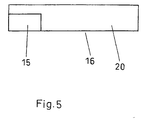
- FIG. 5 shows the rear side 20 of the module 16. At the back of the module 16 is a connector element 19, which is connected to the connector elements 13 of the Compartments is compatible.
- the connector elements z. B. all with each other be compatible, so that any module in one any compartment is pluggable.
- the connector elements but can also be designed module-specific, so that in a compartment can only be plugged into the module intended for this compartment is, but another module does not fit the Plug connection.
- the invention is especially for a multimedia system in one Motor vehicle suitable, but not to this application limited. It is generally used for electronic equipment with in a rack or housing housed modules and outside the housing arranged modules suitable.
Landscapes
- Engineering & Computer Science (AREA)
- Mechanical Engineering (AREA)
- Fittings On The Vehicle Exterior For Carrying Loads, And Devices For Holding Or Mounting Articles (AREA)
- Casings For Electric Apparatus (AREA)
- Connector Housings Or Holding Contact Members (AREA)
Description
- Figur 1
- ein Blockschaltbild eines Ausführungsbeispiels der Erfindung,
- Figur 2
- ein Gestell des Ausführungsbeispieles in perspektivischer Ansicht,
- Figur 3
- die Rückseite des Gestells,
- Figur 4
- ein in ein Fach des Gestells steckbares Modul in perspektivischer Ansicht und
- Figur 5
- die Rückseite des Moduls.
- 1
- Autoradio
- 2
- CD-Spieler
- 3
- DVD-Spieler
- 4
- Kassettenspieler
- 5
- Navigationsgerät
- 6
- Bedienvorrichtung
- 7
- Anzeigevorrichtung
- 8
- Lautsprecher
- 9
- Lautsprecher
- 10
- Bildschirm
- 11
- gemeinsame Busleitung
- 12
- Gestell
- 13
- Steckverbindungselement
- 14
- erste Busleitung
- 15
- zweite Busleitung
- 16
- Modul
- 17
- Anschluß für zweite Busleitung
- 18
- Fach
- 19
- Steckverbindungselement
- 20
- Rückseite
Claims (8)
- Elektronische Anlage mit einem Gehäuse oder einem Gestell (12) mit mehreren Fächern (18) zur Aufnahme von Modulen (1, 2, 3, 4, 5; 16), wobei
für jedes Fach (18) ein Steckverbindungselement (13) zum Anschließen eines in das Fach (18) steckbaren Moduls (1, 2, 3, 4, 5; 16) mit einem passenden Steckverbindungselement (19) vorgesehen ist,
alle Steckverbindungselemente (13) der Fächer (18) über eine erste Busleitung (14) miteinander verbunden sind, an die außerhalb des Gehäuses oder des Gestells (12) angeordnete Module (7, 8, 9) über eine zweite Busleitung (15) anschließbar sind, und
die erste und die zweite Busleitung (14, 15) eine gemeinsame Busleitung (11) bilden, dadurch gekennzeichnet, dass
die gemeinsame Busleitung (11) als Ringleitung ausgebildet ist. - Elektronische Anlage nach Anspruch 1, dadurch gekennzeichnet, dass die Steckverbindungselemente (13, 19) modulspezifisch ausgeführt sind.
- Elektronische Anlage nach Anspruch 1 oder 2, dadurch gekennzeichnet, dass alle Steckverbindungen (13) der Fächer (18) untereinander und alle dazu passenden Steckverbindungen (19) der Module (16) untereinander gleich sind, so dass jedes Modul in jedes Fach steckbar ist.
- Elektronische Anlage nach einem der vorangegangenen Ansprüche, dadurch gekennzeichnet, dass eine Bedienvorrichtung (6) an die gemeinsame Busleitung (11) angeschlossen ist.
- Elektronische Anlage nach einem der vorangegangenen Ansprüche, dadurch gekennzeichnet, dass eine optische und/oder akustische Anzeigevorrichtung (7) zur Anzeige von Informationen an die gemeinsame Busleitung (11) angeschlossen ist.
- Elektronische Anlage nach einem der vorangegangenen Ansprüche, dadurch gekennzeichnet, dass zumindest ein Teil der Module (1, 2, 3, 4, 5, 6, 7, 8, 9, 10) Multimediageräte sind.
- Elektronische Anlage nach einem der vorangegangenen Ansprüche, dadurch gekennzeichnet, dass das Gehäuse oder Gestell (12) in ein Kraftfahrzeug einbaubar ist.
- Elektronische Anlage nach Anspruch 7, dadurch gekennzeichnet, dass das Gehäuse oder das Gestell (12) in die Mittelkonsole des Kraftfahrzeugs einbaubar ist.
Applications Claiming Priority (2)
| Application Number | Priority Date | Filing Date | Title |
|---|---|---|---|
| DE10024126A DE10024126B4 (de) | 2000-05-18 | 2000-05-18 | Elektronische Anlage mit einem Gehäuse oder Gestell und Gestell oder Gehäuse für Module |
| DE10024126 | 2000-05-18 |
Publications (3)
| Publication Number | Publication Date |
|---|---|
| EP1155915A2 EP1155915A2 (de) | 2001-11-21 |
| EP1155915A3 EP1155915A3 (de) | 2003-11-19 |
| EP1155915B1 true EP1155915B1 (de) | 2005-10-26 |
Family
ID=7642367
Family Applications (1)
| Application Number | Title | Priority Date | Filing Date |
|---|---|---|---|
| EP01104090A Expired - Lifetime EP1155915B1 (de) | 2000-05-18 | 2001-02-21 | Elektronische Anlage mit einem Gehäuse oder Gestell für Module |
Country Status (4)
| Country | Link |
|---|---|
| US (1) | US6727606B2 (de) |
| EP (1) | EP1155915B1 (de) |
| AT (1) | ATE307741T1 (de) |
| DE (2) | DE10024126B4 (de) |
Families Citing this family (13)
| Publication number | Priority date | Publication date | Assignee | Title |
|---|---|---|---|---|
| DE10024126B4 (de) * | 2000-05-18 | 2004-02-05 | Harman Becker Automotive Systems (Becker Division) Gmbh | Elektronische Anlage mit einem Gehäuse oder Gestell und Gestell oder Gehäuse für Module |
| US20030215235A1 (en) * | 2002-05-17 | 2003-11-20 | Yazaki Corporation | Optical communication system for vehicle, signal relay apparatus and optical communication connector |
| US20030231570A1 (en) * | 2002-06-14 | 2003-12-18 | Fuji Photo Film Co., Ltd. | Recording and reproducing device |
| WO2004030991A1 (de) * | 2002-09-27 | 2004-04-15 | Robert Bosch Gmbh | Einrichtung zum bereitstellen und verteilen von signalen von multimediageräten in fahrzeugen |
| US7184259B2 (en) | 2004-04-06 | 2007-02-27 | Delphi Technolgies, Inc. | Portable entertainment device |
| US20060035586A1 (en) * | 2004-08-13 | 2006-02-16 | Jernigan Steven R | S-Ray universal CD recorder |
| US20060075436A1 (en) * | 2004-09-27 | 2006-04-06 | Schedivy George C | Plug-in television tuner module and method thereof |
| US7590382B2 (en) | 2004-12-15 | 2009-09-15 | Audiovox Corporation | Entertainment system for use in a vehicle |
| EP1722617B1 (de) * | 2005-05-12 | 2007-11-21 | Harman Becker Automotive Systems GmbH | Elektronische Vorrichtung |
| CA2537483A1 (en) * | 2006-02-22 | 2007-08-22 | Sonic Integrity Canada Ltd. | Adjustable mounting system for multimedia wall shelf units |
| US7990724B2 (en) | 2006-12-19 | 2011-08-02 | Juhasz Paul R | Mobile motherboard |
| US8991772B2 (en) | 2011-09-02 | 2015-03-31 | Toyota Motor Engineering & Manufacturing North America, Inc. | Instrument panel assembly |
| JP2022092394A (ja) * | 2020-12-10 | 2022-06-22 | 株式会社豊田自動織機 | 車両 |
Family Cites Families (18)
| Publication number | Priority date | Publication date | Assignee | Title |
|---|---|---|---|---|
| ES376445A1 (es) * | 1969-02-22 | 1972-04-16 | Semprini | Aparato de amplificacion centralizado. |
| FR2461299B1 (fr) * | 1979-07-09 | 1986-09-05 | Telediffusion Fse | Memoire bloc-note pour cassettes d'enregistrement de bandes magnetiques |
| DE3104630A1 (de) * | 1981-02-10 | 1982-08-19 | Siemens AG, 1000 Berlin und 8000 München | Elektronikeinheit |
| DE3726784A1 (de) * | 1987-08-12 | 1989-02-23 | Grundig Emv | Autoradio mit mehreren zusatzgeraeten |
| CA1340400C (en) * | 1989-01-31 | 1999-02-16 | Philip Miller | Vehicle data system |
| DE4201657A1 (de) * | 1991-02-19 | 1992-10-22 | United Technologies Automotive | Vorrichtung zur fernbetaetigung der beleuchtung in dem fahrgastraum eines fahrzeuges |
| US5339362A (en) * | 1992-01-07 | 1994-08-16 | Rockford Corporation | Automotive audio system |
| JPH11348678A (ja) * | 1998-06-08 | 1999-12-21 | Yazaki Corp | センタークラスタモジュール |
| DE29511005U1 (de) * | 1995-07-06 | 1995-09-14 | Peacock AG, 33181 Wünnenberg | Erweiterbares Multi-Media Endgerät |
| JP3105163B2 (ja) * | 1996-04-23 | 2000-10-30 | 株式会社ハーネス総合技術研究所 | 車内インストルメントパネル用カバーパネル及びその組立方法並びにそのカバーパネルを使用した車載用電子装置の組立方法 |
| US5909357A (en) * | 1997-04-24 | 1999-06-01 | Orr; Tom | Vertically stacked computer modules shaped to indicate compatibility with vertical cooling shaft extending throughout |
| JP3638787B2 (ja) * | 1997-04-28 | 2005-04-13 | 矢崎総業株式会社 | センタークラスタモジュールシステム |
| US5978821A (en) * | 1997-09-17 | 1999-11-02 | Automated Business Companies | Smart modular electronic machine |
| TW347105U (en) * | 1997-09-19 | 1998-12-01 | Mitac Int Corp | Integrated-type computer |
| JP3259954B2 (ja) * | 1997-12-18 | 2002-02-25 | 株式会社オートネットワーク技術研究所 | 車載用ユニット |
| US6147938A (en) * | 1998-09-11 | 2000-11-14 | Mazda Motor Corporation | Vehicle electronic system |
| DE10024126B4 (de) * | 2000-05-18 | 2004-02-05 | Harman Becker Automotive Systems (Becker Division) Gmbh | Elektronische Anlage mit einem Gehäuse oder Gestell und Gestell oder Gehäuse für Module |
| JP3692915B2 (ja) * | 2000-08-08 | 2005-09-07 | トヨタ自動車株式会社 | 車両用電子機器システム |
-
2000
- 2000-05-18 DE DE10024126A patent/DE10024126B4/de not_active Expired - Fee Related
-
2001
- 2001-02-21 EP EP01104090A patent/EP1155915B1/de not_active Expired - Lifetime
- 2001-02-21 DE DE50107794T patent/DE50107794D1/de not_active Expired - Lifetime
- 2001-02-21 AT AT01104090T patent/ATE307741T1/de not_active IP Right Cessation
- 2001-05-16 US US09/859,227 patent/US6727606B2/en not_active Expired - Lifetime
Also Published As
| Publication number | Publication date |
|---|---|
| ATE307741T1 (de) | 2005-11-15 |
| DE50107794D1 (de) | 2005-12-01 |
| EP1155915A3 (de) | 2003-11-19 |
| DE10024126B4 (de) | 2004-02-05 |
| DE10024126A1 (de) | 2001-11-29 |
| EP1155915A2 (de) | 2001-11-21 |
| US20020050384A1 (en) | 2002-05-02 |
| US6727606B2 (en) | 2004-04-27 |
Similar Documents
| Publication | Publication Date | Title |
|---|---|---|
| EP1155915B1 (de) | Elektronische Anlage mit einem Gehäuse oder Gestell für Module | |
| EP0990310B1 (de) | Kraftfahrzeug-einbauvorrichtung für mobiltelefon | |
| DE69829251T2 (de) | Elektrisches Verteilersystem | |
| DE10105292A1 (de) | Zentrale Fahrzeug-Baugruppen-Anbringungsstruktur mit elektrischem Anschluss | |
| DE102009029166A1 (de) | Modularer Stromverteiler | |
| DE102017218378A1 (de) | Elektronikkomponenteneinheit, elektrischer Anschlusskasten und Kabelbaum | |
| DE10164799B4 (de) | Mobiltelefoneinrichtung mit mehradrigen elektrischen Verbindungseinrichtungen | |
| EP0297667B1 (de) | Mobilfunkanlage | |
| DE69610740T2 (de) | Anordnung zur mechanischen und elektrischen Verbindung zwischen elektronischen, in Einbaugeräten integrierten Baugruppen | |
| DE202008004580U1 (de) | Vorrichtung zur Aufnahme eines mobilen Endgerätes | |
| DE102011005704A1 (de) | Elektronische Steuervorrichtung | |
| DE10148470A1 (de) | Vorrichtung und Verfahren zum elektrischen und mechanischen Verbinden von Komponenten eines Automatisierungssystems | |
| EP1978600B1 (de) | Platinenanordnung | |
| AT394690B (de) | Schaltkreisanordnung fuer bordnetze von fahrzeugen | |
| DE69508015T2 (de) | Zentralelektrik für Kraftfahrzeuge | |
| EP0476254A1 (de) | Einrichtung für den Einbau eines Audio- oder Videowiedergabegerätes in ein Kraftfahrzeug | |
| DE10113905C2 (de) | Mobiltelefoneinrichtung mit mehradrigen elektrischen Verbindungseinrichtungen | |
| DE2409318C2 (de) | Sprechstelle für eine Gegen- und/oder Wechselsprechanlage | |
| EP1328422B1 (de) | Knotenpunkt eines daten-busses eines kraftfahrzeuges | |
| DE20002852U1 (de) | Adapter zum Anschluss eines Mobiltelefons an ein Audiogerät eines Kraftfahrzeuges sowie Audiogerät zur Aufnahme eines derartigen Adapters | |
| DE20120882U1 (de) | Halterung für ein Mobiltelefon | |
| DE69619934T2 (de) | Kabelbaumanlage für das Armaturenbrett eines Fahrzeuges | |
| DE10329707A1 (de) | Datenbussystem mit einer Mehrzahl von an zumindest eine Busleitung angeschlossenen Busteilnehmern | |
| DE3125809A1 (de) | Gehaeuse fuer die aufnahme wenigstens einer elektrischen geraetebaugruppe | |
| DE102011011995A1 (de) | Elektronikgerät, aufgebaut aus mindestens zwei Funktionsmodulen |
Legal Events
| Date | Code | Title | Description |
|---|---|---|---|
| PUAI | Public reference made under article 153(3) epc to a published international application that has entered the european phase |
Free format text: ORIGINAL CODE: 0009012 |
|
| AK | Designated contracting states |
Kind code of ref document: A2 Designated state(s): AT BE CH CY DE DK ES FI FR GB GR IE IT LI LU MC NL PT SE TR |
|
| AX | Request for extension of the european patent |
Free format text: AL;LT;LV;MK;RO;SI |
|
| PUAL | Search report despatched |
Free format text: ORIGINAL CODE: 0009013 |
|
| AK | Designated contracting states |
Kind code of ref document: A3 Designated state(s): AT BE CH CY DE DK ES FI FR GB GR IE IT LI LU MC NL PT SE TR |
|
| AX | Request for extension of the european patent |
Extension state: AL LT LV MK RO SI |
|
| 17P | Request for examination filed |
Effective date: 20040129 |
|
| 17Q | First examination report despatched |
Effective date: 20040305 |
|
| AKX | Designation fees paid |
Designated state(s): AT BE CH CY DE DK ES FI FR GB GR IE IT LI LU MC NL PT SE TR |
|
| GRAP | Despatch of communication of intention to grant a patent |
Free format text: ORIGINAL CODE: EPIDOSNIGR1 |
|
| RTI1 | Title (correction) |
Free format text: ELECTRONIC EQUIPMENT WITH HOUSING OR FRAME FOR MODULES |
|
| GRAS | Grant fee paid |
Free format text: ORIGINAL CODE: EPIDOSNIGR3 |
|
| GRAA | (expected) grant |
Free format text: ORIGINAL CODE: 0009210 |
|
| AK | Designated contracting states |
Kind code of ref document: B1 Designated state(s): AT BE CH CY DE DK ES FI FR GB GR IE IT LI LU MC NL PT SE TR |
|
| PG25 | Lapsed in a contracting state [announced via postgrant information from national office to epo] |
Ref country code: FI Free format text: LAPSE BECAUSE OF FAILURE TO SUBMIT A TRANSLATION OF THE DESCRIPTION OR TO PAY THE FEE WITHIN THE PRESCRIBED TIME-LIMIT Effective date: 20051026 Ref country code: NL Free format text: LAPSE BECAUSE OF FAILURE TO SUBMIT A TRANSLATION OF THE DESCRIPTION OR TO PAY THE FEE WITHIN THE PRESCRIBED TIME-LIMIT Effective date: 20051026 Ref country code: IE Free format text: LAPSE BECAUSE OF FAILURE TO SUBMIT A TRANSLATION OF THE DESCRIPTION OR TO PAY THE FEE WITHIN THE PRESCRIBED TIME-LIMIT Effective date: 20051026 |
|
| REG | Reference to a national code |
Ref country code: GB Ref legal event code: FG4D Free format text: NOT ENGLISH |
|
| REG | Reference to a national code |
Ref country code: CH Ref legal event code: EP |
|
| REG | Reference to a national code |
Ref country code: IE Ref legal event code: FG4D Free format text: LANGUAGE OF EP DOCUMENT: GERMAN |
|
| REF | Corresponds to: |
Ref document number: 50107794 Country of ref document: DE Date of ref document: 20051201 Kind code of ref document: P |
|
| PG25 | Lapsed in a contracting state [announced via postgrant information from national office to epo] |
Ref country code: GR Free format text: LAPSE BECAUSE OF FAILURE TO SUBMIT A TRANSLATION OF THE DESCRIPTION OR TO PAY THE FEE WITHIN THE PRESCRIBED TIME-LIMIT Effective date: 20060126 Ref country code: SE Free format text: LAPSE BECAUSE OF FAILURE TO SUBMIT A TRANSLATION OF THE DESCRIPTION OR TO PAY THE FEE WITHIN THE PRESCRIBED TIME-LIMIT Effective date: 20060126 Ref country code: DK Free format text: LAPSE BECAUSE OF FAILURE TO SUBMIT A TRANSLATION OF THE DESCRIPTION OR TO PAY THE FEE WITHIN THE PRESCRIBED TIME-LIMIT Effective date: 20060126 |
|
| PG25 | Lapsed in a contracting state [announced via postgrant information from national office to epo] |
Ref country code: ES Free format text: LAPSE BECAUSE OF FAILURE TO SUBMIT A TRANSLATION OF THE DESCRIPTION OR TO PAY THE FEE WITHIN THE PRESCRIBED TIME-LIMIT Effective date: 20060206 |
|
| PG25 | Lapsed in a contracting state [announced via postgrant information from national office to epo] |
Ref country code: AT Free format text: LAPSE BECAUSE OF NON-PAYMENT OF DUE FEES Effective date: 20060221 |
|
| GBT | Gb: translation of ep patent filed (gb section 77(6)(a)/1977) |
Effective date: 20060201 |
|
| PG25 | Lapsed in a contracting state [announced via postgrant information from national office to epo] |
Ref country code: BE Free format text: LAPSE BECAUSE OF NON-PAYMENT OF DUE FEES Effective date: 20060228 Ref country code: MC Free format text: LAPSE BECAUSE OF NON-PAYMENT OF DUE FEES Effective date: 20060228 Ref country code: LU Free format text: LAPSE BECAUSE OF NON-PAYMENT OF DUE FEES Effective date: 20060228 Ref country code: LI Free format text: LAPSE BECAUSE OF NON-PAYMENT OF DUE FEES Effective date: 20060228 Ref country code: CH Free format text: LAPSE BECAUSE OF NON-PAYMENT OF DUE FEES Effective date: 20060228 |
|
| PG25 | Lapsed in a contracting state [announced via postgrant information from national office to epo] |
Ref country code: PT Free format text: LAPSE BECAUSE OF FAILURE TO SUBMIT A TRANSLATION OF THE DESCRIPTION OR TO PAY THE FEE WITHIN THE PRESCRIBED TIME-LIMIT Effective date: 20060327 |
|
| NLV1 | Nl: lapsed or annulled due to failure to fulfill the requirements of art. 29p and 29m of the patents act | ||
| REG | Reference to a national code |
Ref country code: IE Ref legal event code: FD4D |
|
| ET | Fr: translation filed | ||
| PLBE | No opposition filed within time limit |
Free format text: ORIGINAL CODE: 0009261 |
|
| STAA | Information on the status of an ep patent application or granted ep patent |
Free format text: STATUS: NO OPPOSITION FILED WITHIN TIME LIMIT |
|
| 26N | No opposition filed |
Effective date: 20060727 |
|
| REG | Reference to a national code |
Ref country code: CH Ref legal event code: PL |
|
| BERE | Be: lapsed |
Owner name: BECKER G.M.B.H. Effective date: 20060228 |
|
| PG25 | Lapsed in a contracting state [announced via postgrant information from national office to epo] |
Ref country code: TR Free format text: LAPSE BECAUSE OF FAILURE TO SUBMIT A TRANSLATION OF THE DESCRIPTION OR TO PAY THE FEE WITHIN THE PRESCRIBED TIME-LIMIT Effective date: 20051026 |
|
| PG25 | Lapsed in a contracting state [announced via postgrant information from national office to epo] |
Ref country code: CY Free format text: LAPSE BECAUSE OF FAILURE TO SUBMIT A TRANSLATION OF THE DESCRIPTION OR TO PAY THE FEE WITHIN THE PRESCRIBED TIME-LIMIT Effective date: 20051026 |
|
| PGFP | Annual fee paid to national office [announced via postgrant information from national office to epo] |
Ref country code: IT Payment date: 20140225 Year of fee payment: 14 Ref country code: FR Payment date: 20140220 Year of fee payment: 14 |
|
| REG | Reference to a national code |
Ref country code: FR Ref legal event code: ST Effective date: 20151030 |
|
| PG25 | Lapsed in a contracting state [announced via postgrant information from national office to epo] |
Ref country code: IT Free format text: LAPSE BECAUSE OF NON-PAYMENT OF DUE FEES Effective date: 20150221 |
|
| PG25 | Lapsed in a contracting state [announced via postgrant information from national office to epo] |
Ref country code: FR Free format text: LAPSE BECAUSE OF NON-PAYMENT OF DUE FEES Effective date: 20150302 |
|
| PGFP | Annual fee paid to national office [announced via postgrant information from national office to epo] |
Ref country code: DE Payment date: 20160226 Year of fee payment: 16 |
|
| PGFP | Annual fee paid to national office [announced via postgrant information from national office to epo] |
Ref country code: GB Payment date: 20160226 Year of fee payment: 16 |
|
| REG | Reference to a national code |
Ref country code: DE Ref legal event code: R119 Ref document number: 50107794 Country of ref document: DE |
|
| GBPC | Gb: european patent ceased through non-payment of renewal fee |
Effective date: 20170221 |
|
| PG25 | Lapsed in a contracting state [announced via postgrant information from national office to epo] |
Ref country code: DE Free format text: LAPSE BECAUSE OF NON-PAYMENT OF DUE FEES Effective date: 20170901 |
|
| PG25 | Lapsed in a contracting state [announced via postgrant information from national office to epo] |
Ref country code: GB Free format text: LAPSE BECAUSE OF NON-PAYMENT OF DUE FEES Effective date: 20170221 |