EP1155963B1 - Proçédé et dispositif pour alimenter des objets oblongs à une machine d'emballage - Google Patents
Proçédé et dispositif pour alimenter des objets oblongs à une machine d'emballage Download PDFInfo
- Publication number
- EP1155963B1 EP1155963B1 EP01111852A EP01111852A EP1155963B1 EP 1155963 B1 EP1155963 B1 EP 1155963B1 EP 01111852 A EP01111852 A EP 01111852A EP 01111852 A EP01111852 A EP 01111852A EP 1155963 B1 EP1155963 B1 EP 1155963B1
- Authority
- EP
- European Patent Office
- Prior art keywords
- articles
- branch
- hopper
- outlet
- channels
- Prior art date
- Legal status (The legal status is an assumption and is not a legal conclusion. Google has not performed a legal analysis and makes no representation as to the accuracy of the status listed.)
- Expired - Lifetime
Links
- 238000000034 method Methods 0.000 title claims abstract description 11
- 230000003134 recirculating effect Effects 0.000 claims description 7
- 241000208125 Nicotiana Species 0.000 abstract description 2
- 235000002637 Nicotiana tabacum Nutrition 0.000 abstract description 2
- 235000019506 cigar Nutrition 0.000 description 34
- 235000019504 cigarettes Nutrition 0.000 description 6
- 230000005540 biological transmission Effects 0.000 description 3
- 230000015572 biosynthetic process Effects 0.000 description 1
- 230000005484 gravity Effects 0.000 description 1
- 230000000284 resting effect Effects 0.000 description 1
- 238000011144 upstream manufacturing Methods 0.000 description 1
Images
Classifications
-
- B—PERFORMING OPERATIONS; TRANSPORTING
- B65—CONVEYING; PACKING; STORING; HANDLING THIN OR FILAMENTARY MATERIAL
- B65B—MACHINES, APPARATUS OR DEVICES FOR, OR METHODS OF, PACKAGING ARTICLES OR MATERIALS; UNPACKING
- B65B19/00—Packaging rod-shaped or tubular articles susceptible to damage by abrasion or pressure, e.g. cigarettes, cigars, macaroni, spaghetti, drinking straws or welding electrodes
- B65B19/02—Packaging cigarettes
- B65B19/04—Arranging, feeding, or orientating the cigarettes
Definitions
- the present invention relates to a method and a device for feeding elongated articles on a wrapping machine.
- the present invention is particularly advantageous for use in the tobacco industry, and specifically for feeding articles such as cigars, cigarettes or similar.
- Known cigar wrapping machines are equipped with a cigar feed device comprising a hopper with at least one channel underneath.
- the hopper has walls converging towards an outlet from which the channel extends, and houses a mass of cigars oriented a given way.
- the cigars drop by force of gravity towards the outlet and into the channel, along which they are arranged in an orderly column contacting one another, are guided by two opposite parallel walls of the channel, and travel under their own weight and the weight of the cigars inside the hopper.
- Known feed devices have the drawback of the cigars possibly forming bridges, i.e. arc-shaped supporting structures defined by adjacent cigars resting on one another and on the walls of the hopper, and which clog the outlet, thus preventing the cigars from being fed into the channel, and preventing the cigars on top from exerting the weight force required to feed the cigars along the channel.
- FR2372085A discloses a hopper having a filling area and a supply area for cigarettes to be delivered, means to prevent cigarettes from dropping directly into the supply area from the filling area, and sliding channels supporting acceptable cigarettes as they move therethrough into the supply area, and permitting reject cigarettes and cigarette parts to drop out of the hopper.
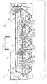
- Number 1 in the accompanying drawing indicates as a whole a device for feeding cigars 2 on a wrapping machine 3 for wrapping each cigar 2 in a respective sheet of wrapping material not shown.
- Device 1 comprises a hopper 4, in turn comprising an inlet 5, four outlets 6, and four channels 7, each of which is connected to a respective outlet 6 and guides cigars 2, arranged in an orderly column 8, to machine 3.
- the cigars 2 inside hopper 4 and channels 7 are oriented in a direction D1 perpendicular to the plane of the accompanying drawing.
- Hopper 4 comprises a front wall and a rear wall not shown in the accompanying drawing; two lateral guides 9 and 10 having respective curved guide surfaces 11 and 12; four conveyors 13 associated with respective channels 7; and a conveyor 14 for recirculating cigars 2.
- Conveyors 13 and 14 partly define a bottom wall 15 of hopper 4, which has a compartment 16 occupied partly by a conveyor 17 dividing compartment 16 into a top portion and a bottom portion connected to the top portion by lateral guides 9 and 10.
- Conveyor 17 extends horizontally, and comprises a transmission pulley 18a located at guide 9; a drive pulley 18b located at guide 10; and a belt 19 looped about pulleys 18a and 18b.
- Pulleys 18a and 18b rotate about respective axes 20a and 20b parallel to direction D1, and conveyor 17 comprises a horizontal top branch 21 and a horizontal bottom branch 22 connected to each other at pulleys 18a and 18b.
- Conveyor 17 is rotated anticlockwise in the accompanying drawing to feed a mass of cigars 2 along an annular path P comprising a portion P1 extending in a horizontal direction D2 between bottom branch 22 and conveyors 13 and 14.
- Guide surface 11 is a portion of a cylinder of radius Ra and axis 20a, and forms with pulley 18a a constant passage section Sa.
- guide surface 12 is a portion of a cylinder of radius Rb and axis 20b, and forms with pulley 18b a constant passage section Sb.
- Pulleys 18a and 18b are equal in diameter, whereas radius Ra is greater than radius Rb so that passage section Sa is greater than passage section Sb.
- Each conveyor 13 comprises two transmission pulleys 23a, 23b and a drive pulley 23c, about which is looped a belt 24, and comprises a top branch 25 sloping slightly downwards from left to right in the accompanying drawing and with respect to direction D2. That is, each branch 25 slopes towards respective channel 7 to assist the downward flow of cigars 2 into channel 7.
- Each channel 7 is defined by a vertical wall 26 tangent to pulley 23b, and by a wall 27 parallel to wall 26 and comprising an appendix 28, which extends about pulley 23b, is substantially parallel to a portion of branch 25, and is fitted on the free end with a revolving roller 29.
- Wall 26 comprises a vertical surface 30 connected to pulley 23b
- wall 27 comprises a surface 31 having a portion parallel to and facing surface 30, a portion extending about the axis of pulley 23b, and a portion parallel to a portion of branch 25.
- Appendix 28 has an upper face 32 on which the cigars 2 in hopper 4 rest, and therefore defines a portion of channel 7 and a portion of bottom wall 15 of hopper 4.
- Each outlet 6 of hopper 4 coincides with the inlet of a respective channel 7, extends between roller 29 and respective branch 25, and has a passage section S6 sized according to the diameter of cigars 2 so as to permit access to respective channel 7 by one cigar 2 at a time.
- Each channel 7 is therefore connected to the hopper by outlet 6, and comprises, as of outlet 6, a straight sloping portion extending between appendix 28 and branch 25; a curved portion extending between appendix 28 and pulley 23b; and a straight vertical portion extending between walls 26 and 27.
- Passage section S6 is substantially perpendicular to direction D2 and path portion P1 to intercept part of the mass of cigars 2.
- Recirculating conveyor 14 comprises a belt 33 looped about two transmission pulleys 34a and 34b and a drive pulley 34c, and comprises a branch 35 sloping upwards in direction D2. That is, branch 25 of the first conveyor 13, on the left in the accompanying drawing, connects guide surface 11 to respective channel 7; branch 35 of conveyor 14 connects face 32 of appendix 28 of the last channel 7, on the right in the accompanying drawing, to guide surface 12; and branches 25 of the central conveyors 13 connect the faces 32 of appendixes 28 of the respective upstream channels 7 to their own respective channels 7.
- the bottom wall 15 of hopper 4 is therefore defined partly by branches 25 and 35, and partly by appendixes 28, and each outlet 6 defines a step in bottom wall 15 for intercepting the cigars 2 traveling along path P.
- cigars 2 are bulk fed continuously or discontinuously in direction D3 into hopper 4 through inlet 5.
- Conveyor 17 is fed continuously anticlockwise in the accompanying drawing, while conveyors 13 and 14 are fed continuously clockwise.
- Top branch 21 of conveyor 17 feeds cigars 2 through passage section Sa and between the bottom branch 22 of conveyor 17 and branch 25 of the first conveyor 13 in direction D2.
- the combined action of conveyor 17 and conveyor 13 feeds cigars 2 in bulk in direction D2, while the cigars 2 traveling in contact with branch 25 are intercepted by outlet 6 and fed through passage section S6 into respective channel 7.
- each conveyor 13 supplies respective outlet 6 and feeds cigars 2 along the respective channel 7; and conveyor 14 cooperates with conveyor 17 to feed some of cigars 2 through passage section Sb and back onto top branch 21 of conveyor 17.
- the number of channels 7 is a design parameter of machine 3, may range from one to a very high number, and obviously determines the number of outlets 6 and conveyors 13.
Landscapes
- Engineering & Computer Science (AREA)
- Mechanical Engineering (AREA)
- Wrapping Of Specific Fragile Articles (AREA)
- Feeding Of Articles To Conveyors (AREA)
- Basic Packing Technique (AREA)
- Filling Or Emptying Of Bunkers, Hoppers, And Tanks (AREA)
Claims (12)
- Procédé pour alimenter en objets oblongs une machine d'emballage comprenant un dispositif comprenant à son tour une trémie d'entrée (4) destinée à loger une masse d'objets (2) orientés dans une première direction (D1), et un certain nombre de canaux (7) destinés à extraire les objets (2) de la trémie d'entrée (4) et dans lesquels les objets (2) sont disposés en une colonne ordonnée (8) ;
le procédé étant caractérisé en ce qu'il comprend les étapes consistant à :alimenter la masse d'objets (2) au moyen d'un orifice d'entrée (5) de la trémie d'entrée (4) à l'intérieur de la trémie d'entrée (4) ;déplacer la masse d'objets (2) à l'intérieur de la trémie d'entrée (4) le long d'une branche de transport d'une trajectoire annulaire (P) à partir de l'orifice d'entrée (5) jusqu'à un orifice de sortie (6) de la trémie d'entrée (4) connecté aux canaux (7) de manière à transporter au moins une partie des objets (2) dans les canaux (7) ; etdéplacer la masse d'objets (2) restante non transportée dans les canaux (7) le long d'une branche de remise en circulation de la trajectoire annulaire (P) à partir de l'orifice de sortie (6) jusqu'à l'orifice d'entrée (5) de manière à remettre en circulation la masse d'objets (2) restante. - Procédé selon la revendication 1, dans lequel l'orifice de sortie (6) est situé le long d'une partie (P1) de la trajectoire annulaire (P) et comprend une section de passage (S6) sensiblement perpendiculaire à la partie (P1) de manière à intercepter les objets (2) alimentés le long de la partie (P1).
- Procédé selon la revendication 1 ou 2, dans lequel les objets (2) sont alimentés en masse le long de la trajectoire annulaire (P) par des moyens de transport motorisés (13, 14, 17).
- Procédé selon l'une quelconque des revendications 1 à 3, dans lequel les objets (2) sont alimentés jusqu'à l'orifice de sortie (6) au moyen d'un convoyeur respectif (13) situé au niveau de l'orifice de sortie (6).
- Procédé selon la revendication 4, dans lequel les objets (2) sont alimentés dans le canal (7) au moyen du convoyeur respectif (13).
- Dispositif pour alimenter en objets oblongs (2) une machine d'emballage (3) ; le dispositif (1) comprenant une trémie d'entrée (4) destinée à loger une masse d'objets (2) orientés dans une première direction (D1), et un certain nombre de canaux (7) destinés à extraire les objets (2) de la trémie d'entrée (4) et dans lesquels les objets (2) sont disposés en une colonne ordonnée (8) ;
le dispositif étant caractérisé en ce qu'il comprend :des moyens de transport principaux (13, 17) destinés à déplacer la masse d'objets (2) à l'intérieur de la trémie d'entrée (4) le long d'une branche de transport d'une trajectoire annulaire (P) à partir de l'orifice d'entrée (5) jusqu'à un orifice de sortie (6) de la trémie d'entrée (4) connectée aux canaux (7) de manière à transporter au moins une partie des objets (2) dans les canaux (7) ; etdes moyens de transport de remise en circulation (14, 17) destinés à déplacer la masse d'objets (2) restante non transportée dans les canaux (7) le long d'une branche de remise en circulation de la trajectoire annulaire (P) à partir de l'orifice de sortie (6) jusqu'à l'orifice d'entrée (5) de manière à remettre en circulation la masse d'objets (2) restante. - Dispositif selon la revendication 6, dans lequel l'orifice de sortie (6) est situé le long d'une partie (P1) de la trajectoire annulaire (P) et comprend une section de passage (S6) sensiblement perpendiculaire à la partie (P1) de manière à intercepter les objets (2) alimentés le long de la partie (P1).
- Dispositif selon la revendication 6 ou 7, dans lequel les moyens de transport principaux (13, 17) comprennent un certain nombre de premiers convoyeurs (13), chacun d'eux étant situé au niveau de l'orifice de sortie (6) et comprenant une branche (25) adjacente à l'orifice de sortie (6) et destinée à alimenter en objets (2) l'orifice de sortie (6).
- Dispositif selon la revendication 8, dans lequel la branche (25) définit une partie d'un canal approprié (7).
- Dispositif selon la revendication 8, dans lequel les moyens de transport principaux (13, 17) comprennent un deuxième convoyeur (17) ayant une branche supérieure (21) et une branche inférieure (22) faisant face à la branche (25) ; la branche inférieure (22) coopérant avec la branche (25) afin d'alimenter la masse d'objets (2) le long d'une partie (P1) de la trajectoire annulaire (P).
- Dispositif selon la revendication 10, dans lequel les moyens de remise en circulation (14, 17) comprennent un troisième convoyeur (14) comprenant une branche (35) faisant face à la branche inférieure (22) ; la branche (35) coopérant avec la branche inférieure (22) afin de transférer la masse d'objets (2) sur la branche supérieure (21).
- Dispositif selon l'une quelconque des revendications 6 à 11, et comprenant un certain nombre de canaux (7) associés à des orifices de sortie (6) respectifs de la trémie d'entrée (4) ; et un certain nombre de premiers convoyeurs (13), chaque premier convoyeur (13) étant associé à un canal (7) respectif.
Applications Claiming Priority (2)
| Application Number | Priority Date | Filing Date | Title |
|---|---|---|---|
| IT2000BO000298A IT1321264B1 (it) | 2000-05-18 | 2000-05-18 | Metodo e dispositivo di alimentazione di articoli di forma allungatain una macchina di incarto. |
| ITBO000298 | 2000-05-18 |
Publications (2)
| Publication Number | Publication Date |
|---|---|
| EP1155963A1 EP1155963A1 (fr) | 2001-11-21 |
| EP1155963B1 true EP1155963B1 (fr) | 2006-07-26 |
Family
ID=11438492
Family Applications (1)
| Application Number | Title | Priority Date | Filing Date |
|---|---|---|---|
| EP01111852A Expired - Lifetime EP1155963B1 (fr) | 2000-05-18 | 2001-05-16 | Proçédé et dispositif pour alimenter des objets oblongs à une machine d'emballage |
Country Status (5)
| Country | Link |
|---|---|
| US (1) | US6513645B2 (fr) |
| EP (1) | EP1155963B1 (fr) |
| AT (1) | ATE334054T1 (fr) |
| DE (1) | DE60121663T2 (fr) |
| IT (1) | IT1321264B1 (fr) |
Families Citing this family (4)
| Publication number | Priority date | Publication date | Assignee | Title |
|---|---|---|---|---|
| US6675952B1 (en) * | 2002-12-02 | 2004-01-13 | Mill Tech Industries | Lumber bin |
| PL210818B1 (pl) * | 2008-05-16 | 2012-03-30 | Int Tobacco Machinery Poland | Zespół magazynująco-transportowy dla podłużnych elementów prętopodobnych, jak również sposób sterowania przepływem masowym oraz napełniania i opróżniania zespołu magazynująco-transportowego dla podłużnych elementów prętopodobnych |
| IT201900019970A1 (it) | 2019-10-29 | 2021-04-29 | Gd Spa | Tramoggia per una macchina impacchettatrice di articoli da fumo. |
| CN111792350B (zh) * | 2020-07-07 | 2021-11-05 | 合肥蓝川生态科技有限公司 | 一种公路施工用可调节方向的沙土转移装置 |
Family Cites Families (7)
| Publication number | Priority date | Publication date | Assignee | Title |
|---|---|---|---|---|
| US2833393A (en) * | 1956-09-25 | 1958-05-06 | Lamb Co F Jos | Distributing conveyor arrangements |
| FR1483632A (fr) * | 1965-06-17 | 1967-06-02 | Tobacco Res & Dev I Proprietar | Distributeurs pour introduire des articles dans un système de transport pneumatique ou pour les extraire de ce système |
| SE344449B (fr) * | 1966-09-21 | 1972-04-17 | Seita | |
| SE308022B (fr) * | 1967-06-20 | 1969-01-27 | Tarkett Ab | |
| GB1491031A (en) * | 1974-10-18 | 1977-11-09 | Molins Ltd | Reservoirs for cigarettes and other similar rod-like articles |
| IT1069444B (it) * | 1976-11-26 | 1985-03-25 | Amf Sasib | Dispositivo per loscarto di sigarette difettose al momento del riempimento di una tramoggia |
| IT1304423B1 (it) * | 1998-11-18 | 2001-03-19 | Gd Spa | Metodo di alimentazione di sigarette ad una bocca di uscita di unatramoggia. |
-
2000
- 2000-05-18 IT IT2000BO000298A patent/IT1321264B1/it active
-
2001
- 2001-05-16 DE DE60121663T patent/DE60121663T2/de not_active Expired - Lifetime
- 2001-05-16 EP EP01111852A patent/EP1155963B1/fr not_active Expired - Lifetime
- 2001-05-16 AT AT01111852T patent/ATE334054T1/de not_active IP Right Cessation
- 2001-05-16 US US09/859,233 patent/US6513645B2/en not_active Expired - Lifetime
Also Published As
| Publication number | Publication date |
|---|---|
| DE60121663T2 (de) | 2007-08-02 |
| IT1321264B1 (it) | 2004-01-08 |
| ATE334054T1 (de) | 2006-08-15 |
| EP1155963A1 (fr) | 2001-11-21 |
| US20020011397A1 (en) | 2002-01-31 |
| DE60121663D1 (de) | 2006-09-07 |
| ITBO20000298A1 (it) | 2001-11-18 |
| US6513645B2 (en) | 2003-02-04 |
Similar Documents
| Publication | Publication Date | Title |
|---|---|---|
| JP2524353B2 (ja) | 二本の無端のシガレット連続体を造るための方法および装置 | |
| AU633937B2 (en) | Distribution device | |
| US4135615A (en) | Tobacco feeding system | |
| JP3138266B2 (ja) | たばこ加工産業における二重連続体製造機のための装填装置 | |
| CN101631479A (zh) | 塔箱排空装置的用于排空装有杆状产品的塔箱的排空料箱 | |
| EP1155963B1 (fr) | Proçédé et dispositif pour alimenter des objets oblongs à une machine d'emballage | |
| CN102984962B (zh) | 烟丝杆制造装置 | |
| US4372710A (en) | Apparatus for manipulating filter rod sections or the like between producing and processing machines | |
| JPH01211480A (ja) | 紙巻きたばこの製造及び包装用の装置 | |
| EP1002721B1 (fr) | Procédé pour alimenter des cigarettes vers la sortie d'une trémie | |
| US3799324A (en) | Automatic cigarette feed machine | |
| US3513962A (en) | Article feeding apparatus | |
| US3633735A (en) | Apparatus for feeding cigarettes or other rodlike articles | |
| US5860427A (en) | Unit for forming group of cigarettes | |
| CN100473295C (zh) | 对过滤嘴连接机器输送过滤嘴的单元 | |
| US7954498B2 (en) | Device for the creating of a homogeneous cut tobacco flow | |
| CS242878B2 (en) | Machine for cigarettes production equipped with tobacco auxiliary supply mechanism | |
| US5273057A (en) | Cigarette manufacturing machine | |
| GB2285381A (en) | Dual rod cigarette manufacturing machine | |
| US3503487A (en) | Article feeding apparatus | |
| JP6751073B2 (ja) | たばこ加工産業での実質的に筒状の物品を製造するための機械及び方法 | |
| WO1999056568A2 (fr) | Machine a fabriquer des cigarettes | |
| US6364091B1 (en) | Conveying device for forming and conveying groups of products | |
| GB2321441A (en) | Cigarette grouping apparatus | |
| JP2005112618A (ja) | 棒状物品の搬送装置 |
Legal Events
| Date | Code | Title | Description |
|---|---|---|---|
| PUAI | Public reference made under article 153(3) epc to a published international application that has entered the european phase |
Free format text: ORIGINAL CODE: 0009012 |
|
| AK | Designated contracting states |
Kind code of ref document: A1 Designated state(s): AT BE CH CY DE DK ES FI FR GB GR IE IT LI LU MC NL PT SE TR |
|
| AX | Request for extension of the european patent |
Free format text: AL;LT;LV;MK;RO;SI |
|
| RIN1 | Information on inventor provided before grant (corrected) |
Inventor name: STAGNI, ALBERTO Inventor name: SPATAFORA, MARIO |
|
| 17P | Request for examination filed |
Effective date: 20020517 |
|
| AKX | Designation fees paid |
Free format text: AT BE CH CY DE DK ES FI FR GB GR IE IT LI LU MC NL PT SE TR |
|
| GRAP | Despatch of communication of intention to grant a patent |
Free format text: ORIGINAL CODE: EPIDOSNIGR1 |
|
| GRAS | Grant fee paid |
Free format text: ORIGINAL CODE: EPIDOSNIGR3 |
|
| GRAA | (expected) grant |
Free format text: ORIGINAL CODE: 0009210 |
|
| RAP1 | Party data changed (applicant data changed or rights of an application transferred) |
Owner name: G.D SOCIETA PER AZIONI |
|
| AK | Designated contracting states |
Kind code of ref document: B1 Designated state(s): AT BE CH CY DE DK ES FI FR GB GR IE IT LI LU MC NL PT SE TR |
|
| PG25 | Lapsed in a contracting state [announced via postgrant information from national office to epo] |
Ref country code: IT Free format text: LAPSE BECAUSE OF FAILURE TO SUBMIT A TRANSLATION OF THE DESCRIPTION OR TO PAY THE FEE WITHIN THE PRESCRIBED TIME-LIMIT;WARNING: LAPSES OF ITALIAN PATENTS WITH EFFECTIVE DATE BEFORE 2007 MAY HAVE OCCURRED AT ANY TIME BEFORE 2007. THE CORRECT EFFECTIVE DATE MAY BE DIFFERENT FROM THE ONE RECORDED. Effective date: 20060726 Ref country code: BE Free format text: LAPSE BECAUSE OF FAILURE TO SUBMIT A TRANSLATION OF THE DESCRIPTION OR TO PAY THE FEE WITHIN THE PRESCRIBED TIME-LIMIT Effective date: 20060726 Ref country code: FI Free format text: LAPSE BECAUSE OF FAILURE TO SUBMIT A TRANSLATION OF THE DESCRIPTION OR TO PAY THE FEE WITHIN THE PRESCRIBED TIME-LIMIT Effective date: 20060726 Ref country code: AT Free format text: LAPSE BECAUSE OF FAILURE TO SUBMIT A TRANSLATION OF THE DESCRIPTION OR TO PAY THE FEE WITHIN THE PRESCRIBED TIME-LIMIT Effective date: 20060726 |
|
| REG | Reference to a national code |
Ref country code: GB Ref legal event code: FG4D |
|
| REG | Reference to a national code |
Ref country code: CH Ref legal event code: EP |
|
| REG | Reference to a national code |
Ref country code: IE Ref legal event code: FG4D |
|
| REF | Corresponds to: |
Ref document number: 60121663 Country of ref document: DE Date of ref document: 20060907 Kind code of ref document: P |
|
| PG25 | Lapsed in a contracting state [announced via postgrant information from national office to epo] |
Ref country code: SE Free format text: LAPSE BECAUSE OF FAILURE TO SUBMIT A TRANSLATION OF THE DESCRIPTION OR TO PAY THE FEE WITHIN THE PRESCRIBED TIME-LIMIT Effective date: 20061026 Ref country code: DK Free format text: LAPSE BECAUSE OF FAILURE TO SUBMIT A TRANSLATION OF THE DESCRIPTION OR TO PAY THE FEE WITHIN THE PRESCRIBED TIME-LIMIT Effective date: 20061026 |
|
| REG | Reference to a national code |
Ref country code: CH Ref legal event code: NV Representative=s name: ISLER & PEDRAZZINI AG |
|
| PG25 | Lapsed in a contracting state [announced via postgrant information from national office to epo] |
Ref country code: ES Free format text: LAPSE BECAUSE OF FAILURE TO SUBMIT A TRANSLATION OF THE DESCRIPTION OR TO PAY THE FEE WITHIN THE PRESCRIBED TIME-LIMIT Effective date: 20061106 |
|
| PG25 | Lapsed in a contracting state [announced via postgrant information from national office to epo] |
Ref country code: PT Free format text: LAPSE BECAUSE OF FAILURE TO SUBMIT A TRANSLATION OF THE DESCRIPTION OR TO PAY THE FEE WITHIN THE PRESCRIBED TIME-LIMIT Effective date: 20061226 |
|
| ET | Fr: translation filed | ||
| PLBE | No opposition filed within time limit |
Free format text: ORIGINAL CODE: 0009261 |
|
| STAA | Information on the status of an ep patent application or granted ep patent |
Free format text: STATUS: NO OPPOSITION FILED WITHIN TIME LIMIT |
|
| 26N | No opposition filed |
Effective date: 20070427 |
|
| REG | Reference to a national code |
Ref country code: CH Ref legal event code: PCAR Free format text: ISLER & PEDRAZZINI AG;POSTFACH 1772;8027 ZUERICH (CH) |
|
| PG25 | Lapsed in a contracting state [announced via postgrant information from national office to epo] |
Ref country code: MC Free format text: LAPSE BECAUSE OF NON-PAYMENT OF DUE FEES Effective date: 20070531 |
|
| PG25 | Lapsed in a contracting state [announced via postgrant information from national office to epo] |
Ref country code: GR Free format text: LAPSE BECAUSE OF FAILURE TO SUBMIT A TRANSLATION OF THE DESCRIPTION OR TO PAY THE FEE WITHIN THE PRESCRIBED TIME-LIMIT Effective date: 20061027 |
|
| PG25 | Lapsed in a contracting state [announced via postgrant information from national office to epo] |
Ref country code: IE Free format text: LAPSE BECAUSE OF NON-PAYMENT OF DUE FEES Effective date: 20070516 |
|
| PG25 | Lapsed in a contracting state [announced via postgrant information from national office to epo] |
Ref country code: CY Free format text: LAPSE BECAUSE OF FAILURE TO SUBMIT A TRANSLATION OF THE DESCRIPTION OR TO PAY THE FEE WITHIN THE PRESCRIBED TIME-LIMIT Effective date: 20060726 Ref country code: LU Free format text: LAPSE BECAUSE OF NON-PAYMENT OF DUE FEES Effective date: 20070516 |
|
| PG25 | Lapsed in a contracting state [announced via postgrant information from national office to epo] |
Ref country code: TR Free format text: LAPSE BECAUSE OF FAILURE TO SUBMIT A TRANSLATION OF THE DESCRIPTION OR TO PAY THE FEE WITHIN THE PRESCRIBED TIME-LIMIT Effective date: 20060726 |
|
| PGFP | Annual fee paid to national office [announced via postgrant information from national office to epo] |
Ref country code: FR Payment date: 20100601 Year of fee payment: 10 |
|
| PGFP | Annual fee paid to national office [announced via postgrant information from national office to epo] |
Ref country code: CH Payment date: 20100525 Year of fee payment: 10 |
|
| REG | Reference to a national code |
Ref country code: CH Ref legal event code: PL |
|
| PG25 | Lapsed in a contracting state [announced via postgrant information from national office to epo] |
Ref country code: CH Free format text: LAPSE BECAUSE OF NON-PAYMENT OF DUE FEES Effective date: 20110531 Ref country code: LI Free format text: LAPSE BECAUSE OF NON-PAYMENT OF DUE FEES Effective date: 20110531 |
|
| REG | Reference to a national code |
Ref country code: FR Ref legal event code: ST Effective date: 20120131 |
|
| PG25 | Lapsed in a contracting state [announced via postgrant information from national office to epo] |
Ref country code: FR Free format text: LAPSE BECAUSE OF NON-PAYMENT OF DUE FEES Effective date: 20110531 |
|
| PGFP | Annual fee paid to national office [announced via postgrant information from national office to epo] |
Ref country code: GB Payment date: 20160527 Year of fee payment: 16 |
|
| GBPC | Gb: european patent ceased through non-payment of renewal fee |
Effective date: 20170516 |
|
| PG25 | Lapsed in a contracting state [announced via postgrant information from national office to epo] |
Ref country code: GB Free format text: LAPSE BECAUSE OF NON-PAYMENT OF DUE FEES Effective date: 20170516 |
|
| PGFP | Annual fee paid to national office [announced via postgrant information from national office to epo] |
Ref country code: NL Payment date: 20190526 Year of fee payment: 19 |
|
| PGFP | Annual fee paid to national office [announced via postgrant information from national office to epo] |
Ref country code: DE Payment date: 20200528 Year of fee payment: 20 |
|
| REG | Reference to a national code |
Ref country code: NL Ref legal event code: MM Effective date: 20200601 |
|
| PG25 | Lapsed in a contracting state [announced via postgrant information from national office to epo] |
Ref country code: NL Free format text: LAPSE BECAUSE OF NON-PAYMENT OF DUE FEES Effective date: 20200601 |
|
| REG | Reference to a national code |
Ref country code: DE Ref legal event code: R071 Ref document number: 60121663 Country of ref document: DE |