EP1156155B1 - Section de séchage d'une machine de fabrication de papier ou carton - Google Patents
Section de séchage d'une machine de fabrication de papier ou carton Download PDFInfo
- Publication number
- EP1156155B1 EP1156155B1 EP01105067A EP01105067A EP1156155B1 EP 1156155 B1 EP1156155 B1 EP 1156155B1 EP 01105067 A EP01105067 A EP 01105067A EP 01105067 A EP01105067 A EP 01105067A EP 1156155 B1 EP1156155 B1 EP 1156155B1
- Authority
- EP
- European Patent Office
- Prior art keywords
- web
- machine according
- gas
- compressed
- guiding device
- Prior art date
- Legal status (The legal status is an assumption and is not a legal conclusion. Google has not performed a legal analysis and makes no representation as to the accuracy of the status listed.)
- Expired - Lifetime
Links
- 238000004519 manufacturing process Methods 0.000 title 1
- 238000001035 drying Methods 0.000 claims description 48
- 239000004744 fabric Substances 0.000 claims description 17
- 230000035699 permeability Effects 0.000 claims description 5
- 239000011888 foil Substances 0.000 claims description 4
- 230000001105 regulatory effect Effects 0.000 claims description 2
- 239000000463 material Substances 0.000 description 18
- 238000007605 air drying Methods 0.000 description 2
- 238000005188 flotation Methods 0.000 description 2
Images


Classifications
-
- D—TEXTILES; PAPER
- D21—PAPER-MAKING; PRODUCTION OF CELLULOSE
- D21F—PAPER-MAKING MACHINES; METHODS OF PRODUCING PAPER THEREON
- D21F5/00—Dryer section of machines for making continuous webs of paper
- D21F5/18—Drying webs by hot air
- D21F5/185—Supporting webs in hot air dryers
-
- D—TEXTILES; PAPER
- D21—PAPER-MAKING; PRODUCTION OF CELLULOSE
- D21F—PAPER-MAKING MACHINES; METHODS OF PRODUCING PAPER THEREON
- D21F5/00—Dryer section of machines for making continuous webs of paper
-
- D—TEXTILES; PAPER
- D21—PAPER-MAKING; PRODUCTION OF CELLULOSE
- D21F—PAPER-MAKING MACHINES; METHODS OF PRODUCING PAPER THEREON
- D21F5/00—Dryer section of machines for making continuous webs of paper
- D21F5/18—Drying webs by hot air
Definitions
- the invention relates to a machine for producing a paper or board web with a press section and arranged after the press section dryer section, which has a plurality of drying cylinders with smooth contact surface and in which at least one designed as a floating dryer gas-operated web guide means is provided by the web together with a Sieve is passed.
- the paper web is guided for drying over steam-heated cylinders or over steam-heated cylinders and suction suction rolls.
- the wet paper web still does not have sufficient strength, but now occur with respect to the web guide often problems that are particularly due to the fact that the still wet and poorly ventilated web stick to the smooth contact surfaces, for a sufficient heat transfer are absolutely necessary.
- sufficient web tension is necessary, which can only be generated by train, ie corresponding differential speeds, before or directly after the first smooth contact surface. However, this often leads to web breaks and overstretching of the web edges.
- DE 196 05 195 proposes to guide the web around a non-contact drying device.
- the web is supported on the one hand on the air cushion of the drying device and on the other hand on the sieve.
- FR 2 439 959 discloses the use of a suspended bed dryer for drying fabrics.
- the aim of the invention is to provide a machine of the type mentioned, in which at the same time both a very optimal drying rate at the beginning of the drying and a secure web guide is ensured at high machine speed.
- At least one compressed-gas-operated web guiding device designed as a floating dryer can be provided directly after the press section and before the first drying cylinder.
- a web of low strength e.g., at high humidity such as prior to cylinder drying
- the screen in the respective compressed-gas-operated web guiding device generally has an at least substantially rectilinear course.
- the web guiding device expediently comprises a plurality of nozzles arranged one behind the other in the web running direction for pressurizing gas of the web, such nozzles preferably being provided on both sides of the web.
- a plurality of nozzle bars each extending in the direction of the web width may be provided.
- air can be provided as compressed gas.
- At least one impingement-flow dryer provided with at least one dryer hood is provided, through which the web can be subjected to a hot-air and / or hot-steam impact flow.
- the web is preferably guided over at least one particular larger support roller with associated impingement dryer.
- Such an impingement flow dryer is also preferably arranged again in front of the first drying cylinder.
- the web Before the web is first pulled off a smooth heated surface, it can therefore be pre-dried by at least one floating dryer and optionally at least one impingement dryer.
- the gas or air drying is advantageously carried out until a sufficient dry content is reached at which the required web tension can be applied easily.
- the web already has a dry content higher than about 58 to about 65 ° when drained from the first dryer cylinder or when first drawn from a smooth heated surface.
- a part of the gas or air drying can also take place by means of an impingement-flow dryer or an impingement hood.
- At least one pressurized-gas-operated web guiding device is initially provided.
- the web, following the last press nip of the press section is first guided through at least one compressed-gas-operated web guiding device and subsequently via at least one, in particular, larger support roll with associated impingement dryer, before it is fed to the first drying cylinder.
- the drying speed in the region of a respective web guiding device designed as a floating dryer or of a respective impingement flow dryer is advantageously adjustable via the pressure gas temperature, speed and / or moisture.
- the air permeability of a screen associated with a respective compressed-gas-operated web guiding device is preferably chosen as high as possible.
- this air permeability of the respective sieve is greater than about 1 . 52 ⁇ m 3 m 2 ⁇ s (300 cfm ). and preferably greater than about 2 . 54 ⁇ m 3 m 2 ⁇ s (500 cfm ).
- the web from the press section directly to that of a compressed-gas-operated web guiding device assigned sieve is passed.
- the transfer of the web from the press section to the screen assigned to a compressed-gas-operated guide device can also take place via at least one transfer belt or the like.
- the web can be removed from a run through the last Preßnip the press section felt (upper or lower felt). But it is also a decrease directly from a last Preßnip the press section associated press roll conceivable.
- a respective compressed-gas-operated web guiding device can be arranged horizontally, vertically or obliquely.
- the web may be generally obliquely upwards or generally obliquely downwards in the inclined gas-operated web guiding device.
- a plurality of compressed-gas-operated web guiding devices are provided, at least a part of these web guiding devices can each be assigned a separate sieve.
- suction rolls, transfer foils and / or suction boxes can be provided before and / or after the associated compressed-gas-operated web guiding device and / or between successive web guiding devices.
- the roll (suction roll or cylinder) following the last float dryer may be partially wrapped around the screen associated with the float dryer, or the web may be transferred from a suction roll to a subsequent dryer fabric.
- the web is expediently pressed against the wire and / or sucked. This is possible, for example, in that the web to be transferred is subjected to negative pressure in a respective compressed-gas-operated web guiding device only on its side facing away from the wire and in the web running direction with compressed gas and / or from the wire side.
- vacuum boxes may be arranged between the nozzle bars provided on the screen side facing away from the web.
- the transfer through the gas or air dryer is preferably carried out web width through the air dryer.
- the transfer can also be done partially or completely with Koch Kunststoffbändel and appropriate transfer zones in suction and blow boxes.
- a Math211bмаels must be taken to ensure that the rest of the web can be driven before the corresponding gas or air dryer from the felt or wire with an additional removal device in the pulper or basement.
- At least one web guide device is provided, through which the web can be acted upon by compressed gas at low temperature in the range of preferably approximately 20 to approximately 150 °.
- compressed gas at low temperature in the range of preferably approximately 20 to approximately 150 °.
- At least one floating dryer without a sieve can be provided between the last press nip of the press section and the first drying cylinder and / or within a pre-drying section.
- the inventive operated as a float dryer gas-operated Schwebe operations learned (possibly in conjunction with at least one impingement dryer) is at the beginning of the drying between the press and the first drying cylinder, preferably in combination with a tandem NipcoFlex press or DuoCentri press with band around the central roll or other press configurations, at where the web is not pulled off a smooth roll used.
- FIG. 1 shows, in a schematic partial representation, a web guiding device 10 which is operated with compressed gas, in this case compressed air, and which is designed as a floating dryer.
- compressed gas in this case compressed air
- the web guide device 10 is assigned to a web 12 serving the web support, which is passed together with the web 14 through the web guide device 10.
- the material web 14 is a paper or board web.
- the material web 14 is acted upon by compressed air so that it is lifted in the web running direction L alternately from the wire 12 and rests against this. Due to the air permeability, the screen 12 has an at least substantially straight course within the web guiding device.
- the web guide device 10 For corresponding loading of the material web 14, the web guide device 10 comprises a plurality of nozzles 16 arranged one behind the other in the web running direction L.
- nozzles 16 are provided on both sides of the wire 12 and corresponding to the material web.
- a plurality of each extending in the direction of the web width nozzle beam 16 are provided on both sides.
- the air permeability of the screen 12 is suitably greater than about 1 . 52 ⁇ m 3 m 2 ⁇ s (300 cfm ) and preferably greater than about 2 . 54 ⁇ m 3 m 2 ⁇ s (500 cfm ).
- the nozzles 16 can be designed and / or controlled such that, for transferring the material web 14, the web 14 in the web guiding device 10 only on its side facing away from the wire 12 and in Web running direction L with pressurized gas, here compressed air, is acted upon.
- pressurized gas here compressed air
- the material web 14 but also from the screen side through the wire 12 through are subjected to negative pressure.
- vacuum boxes (not shown) can be arranged between the nozzle bars provided on the lower screen side 16.
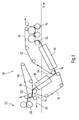
- FIGS 2 and 3 show in a purely schematic representation in each case a drying section 18 of a machine for producing a material web, which is a paper or board web.
- two web guiding devices 10, 10 'of the type described in FIG. 1 are provided in each case. These two web guiding devices 10, 10 'are respectively arranged after the last press nip 20 of the press section 22 and before the first drying cylinder 24 of the dryer section 18.
- an impingement dryer 28 provided with a dryer or impingement hood 26 is provided between the two web guiding devices 10, 10 ', through which the material web 14 can be subjected to a hot air and / or superheated steam impingement flow.
- the material web 14 with a special the screen 30 associated with the impingement dryer 28 is guided over a larger support roller 32 provided with the dryer hood 26.
- the drying speed in the region of a respective web guiding device 10, 10 'designed as a floating dryer or of the impingement flow dryer 28 still provided in the embodiment according to FIG. 2 can be regulated via the compressed air temperature, speed and / or humidity.
- the drying may take place, for example, in such a way that the material web 14 (see also FIG. 1) already has a dry content when draining from the first drying cylinder 18 or during the first removal from a smooth heated surface, which is preferably higher than approximately 60 to about 65%.
- the web 14 is supplied in both cases, starting from the last Preßnip 20 of the press section 22 to the first drying cylinder 18 in a closed train. In this case, the material web 14 is removed in each case from the bottom felt 34 guided through the last press nip 20 of the press section 22.
- a common sieve 12 is guided by the two web guiding devices 10, 10 '.
- the material web 14 is removed in the area of a suction roll 36 from the bottom felt 34 guided through the last press nip 20 of the press section 22.
- the wire 12 is guided over a further suction roller 38.
- a suction roll 40 is provided, over which the wire 12 is guided.
- the material web 14 is taken over by the sieve 30 assigned to the impingement flow dryer 28.
- a transfer foil 44, a suction box 46 or the like may be provided at the transfer location.
- a suction box 46 or the like may be provided at the transfer location.
- the material web 14 is transferred from the wire 30 to a drying wire 44, through which the web is finally fed to the first drying cylinder 18.
- the material web 14 is guided generally obliquely downward in the first web guiding device 10 and generally obliquely upward in the second web guiding device 10 '.
- the transfer of the web 14 from the wire 12 to the through the second web guide means 10 'guided screen 12' takes place in the region of another, the screen 12 'associated with the suction roll 54.
- the sieve 12 'simultaneously serves as a drying sieve, through which the material web 14 is fed to the first drying cylinder 18 via a further suction roll 56 following the second web guiding device 10'.
- At least one of the compressed-gas-operated web guiding device 10, 10 ' is designed as a floating dryer. In principle, however, it is also conceivable to operate one of these web guiding devices 10, 10 'with compressed gas or compressed air at low temperature and, for example, to use it at least predominantly as a transfer element.
- At least one floating dryer without a sieve between the last press nip 20 of the press section 22 and the first drying cylinder 18 and / or within a pre-drying section.
Landscapes
- Paper (AREA)
- Drying Of Solid Materials (AREA)
Claims (32)
- Machine de fabrication d'une bande de papier ou de carton comprenant une section de pressage et une section de séchage (18) disposée après la section de pressage (22), laquelle présente plusieurs cylindres de séchage ayant une surface de contact lisse et dans laquelle il est prévu au moins un dispositif de guidage de bande (10, 10') à gaz comprimé réalisé sous forme de sécheur à suspension, à travers lequel est guidée la bande (14) conjointement avec une toile (12, 12'),
caractérisée en ce que
l'au moins un dispositif de guidage de bande (10, 10') à gaz comprimé réalisé sous forme de sécheur à suspension est disposé avant le premier cylindre de séchage (18) et en ce que la bande (14) peut être sollicitée avec du gaz comprimé sous pression dans l'au moins un dispositif de guidage de bande (10, 10') à gaz comprimé réalisé sous forme de sécheur à suspension de telle sorte qu'elle soit, en alternance, soulevée de la toile (12, 12') dans la direction d'avance de la bande (L) et appliquée contre celle-ci. - Machine selon la revendication 1,
caractérisée en ce que
la toile (12, 12') est guidée en ligne droite à travers le dispositif de guidage de bande (10, 10') à gaz comprimé. - Machine selon l'une quelconque des revendications précédentes,
caractérisée en ce que
le dispositif de guidage de bande (10, 10') comprend, pour solliciter la bande (14) avec du gaz comprimé, plusieurs buses (16) disposées les unes derrière les autres dans la direction d'avance de la bande (L). - Machine selon la revendication 3,
caractérisée en ce que
des buses (16) sont prévues des deux côtés de la toile (12, 12'). - Machine selon la revendication 3 ou 4,
caractérisée en ce que
l'on prévoit plusieurs barres à buses (16) s'étendant à chaque fois dans la direction de la largeur de la bande. - Machine selon l'une quelconque des revendications précédentes,
caractérisée en ce que
l'on prévoit de l'air en tant que gaz comprimé. - Machine selon l'une quelconque des revendications précédentes,
caractérisée en ce que
l'on prévoit au moins un sécheur à écoulement incident (28) pourvu d'au moins une hotte de séchage (26), par lequel la bande (14) peut être sollicitée avec un écoulement incident d'air chaud et/ou de vapeur chaude. - Machine selon la revendication 7,
caractérisée en ce que
la bande (14) est guidée sur au moins un cylindre de support ou aspirant (32) avec un sécheur à écoulement incident associé (28). - Machine selon la revendication 7 ou 8,
caractérisée en ce que
l'on dispose au moins un sécheur à écoulement incident (28) avant le premier cylindre de séchage (18). - Machine selon l'une quelconque des revendications 7 à 9,
caractérisée en ce que
le sécheur à écoulement incident (28) est disposé dans la direction d'avance de la bande (L) derrière au moins un dispositif de guidage de bande à gaz comprimé (10, 10'). - Machine selon l'une quelconque des revendications précédentes,
caractérisée en ce que
la bande (14) possède déjà à sa sortie du premier cylindre de séchage (18) ou à son premier retrait d'une surface chauffée lisse une teneur en matières sèches supérieure à environ 58 à 65%. - Machine selon l'une quelconque des revendications précédentes,
caractérisée en ce que
suite à la dernière ligne de pressage (20) de la section de pressage (22), on prévoit d'abord au moins un dispositif de guidage de bande à gaz comprimé (10, 10'). - Machine selon l'une quelconque des revendications précédentes,
caractérisée en ce que
la bande (14) est guidée suite à la dernière ligne de pressage (20) de la section de pressage (22) d'abord à travers au moins un dispositif de guidage de bande à gaz comprimé (10, 10') puis sur au moins un cylindre de support ou aspirant (32) avec le sécheur à écoulement incident associé (28), avant qu'elle ne soit acheminée au premier cylindre de séchage (18). - Machine selon l'une quelconque des revendications précédentes,
caractérisée en ce que
la vitesse de séchage peut être régulée dans la région d'un dispositif de guidage de bande respectif (10, 10') réalisé sous forme de sécheur à suspension, ou d'un sécheur à écoulement incident respectif (28), par le biais de la température, de la vitesse et/ou de l'humidité du gaz comprimé. - Machine selon l'une quelconque des revendications précédentes,
caractérisée en ce que
la perméabilité à l'air de la toile (12, 12') associée au dispositif de guidage de bande à gaz comprimé (10, 10') est supérieure à environ 1,52 m3/m2s (300 cfm) et de préférence supérieure à environ 2,54 m3/m2s (500 cfm). - Machine selon l'une quelconque des revendications précédentes,
caractérisée en ce que
la bande (14) est acheminée depuis la dernière ligne de pressage (20) de la section de pressage (22) au premier cylindre de séchage (18) dans un parcours fermé. - Machine selon l'une quelconque des revendications précédentes,
caractérisée en ce que
la bande (14) est transférée de la section de pressage (22) directement à la toile (12) associée au dispositif de guidage de bande à gaz comprimé (10, 10'). - Machine selon l'une quelconque des revendications 1 à 16,
caractérisée en ce que
le transfert de la bande (14) de la section de pressage (22) à la toile (12) associée au dispositif de guidage de bande à gaz comprimé (10, 10') s'effectue par le biais d'au moins une bande de transfert. - Machine selon l'une quelconque des revendications précédentes,
caractérisée en ce que
la bande (14) est prélevée d'un feutre (34) guidé à travers la dernière ligne de pressage (20) de la section de pressage (22). - Machine selon l'une quelconque des revendications 1 à 18,
caractérisée en ce que
la bande (14) est prélevée directement d'un cylindre de pressage associé à la dernière ligne de pressage (20) de la section de pressage (22). - Machine selon l'une quelconque des revendications précédentes,
caractérisée en ce que
l'on prévoit plusieurs dispositifs de guidage de bande (10, 10') réalisés de préférence à chaque fois sous forme de sécheur à suspension et/ou plusieurs sécheurs à écoulement incident (28). - Machine selon l'une quelconque des revendications précédentes,
caractérisée en ce que
l'on prévoit au moins un dispositif de guidage de bande à gaz comprimé (10, 10') disposé horizontalement. - Machine selon l'une quelconque des revendications précédentes,
caractérisée en ce que
l'on prévoit au moins un dispositif de guidage de bande à gaz comprimé (10, 10') disposé verticalement. - Machine selon l'une quelconque des revendications précédentes,
caractérisée en ce que
l'on prévoit au moins un dispositif de guidage de bande à gaz comprimé (10, 10') dans lequel la bande (14) est guidée généralement obliquement vers le haut. - Machine selon l'une quelconque des revendications précédentes,
caractérisée en ce que
l'on prévoit au moins un dispositif de guidage de bande à gaz comprimé (10, 10') dans lequel la bande (14) est guidée généralement obliquement vers le bas. - Machine selon l'une quelconque des revendications précédentes,
caractérisée en ce que
plusieurs dispositifs de guidage de bande à gaz comprimé sont prévus et en ce que l'on associe à chaque fois une toile propre (12, 12') à au moins une partie de ces dispositifs de guidage de bande à gaz comprimé (10, 10'). - Machine selon l'une quelconque des revendications précédentes,
caractérisée en ce que
l'on prévoit au moins une toile (12) guidée à travers plusieurs dispositifs de guidage de bande à gaz comprimé (10, 10'). - Machine selon l'une quelconque des revendications précédentes,
caractérisée en ce que
pour maintenir la bande (14) sur la toile (12, 12') avant et/ou après le dispositif de guidage de bande à gaz comprimé associé (10, 10') et/ou entre des dispositifs de guidage de bande successifs (10, 10'), on prévoit des cylindres aspirants (36-40, 54, 56), des feuilles de transfert (44) et/ou des caisses aspirantes (46). - Machine selon l'une quelconque des revendications précédentes,
caractérisée en ce que
pour le transfert de la bande (14), la bande (14) peut être sollicitée dans un dispositif de guidage de bande respectif à gaz comprimé (10, 10') uniquement sur son côté opposé à la toile (12, 12') et dans la direction d'avance de la bande (L) avec du gaz comprimé, et/ou depuis le côté de la toile avec une dépression. - Machine selon l'une quelconque des revendications précédentes,
caractérisée en ce que
l'on dispose entre des barres à buses (16) prévues du côté de la toile opposé à la bande (14) des caisses à dépression. - Machine selon l'une quelconque des revendications précédentes,
caractérisée en ce que
l'on prévoit au moins un dispositif de guidage de bande (10, 10') qui permet de solliciter la bande (14) avec du gaz comprimé à basse température dans la plage préférée d'environ 20 à 150°C. - Machine selon l'une quelconque des revendications précédentes,
caractérisée en ce que
l'on dispose entre la dernière ligne de pressage (20) de la section de pressage (22) et le premier cylindre de séchage (18) et/ou à l'intérieur d'une section de préséchage au moins un sécheur à suspension sans toile.
Applications Claiming Priority (2)
| Application Number | Priority Date | Filing Date | Title |
|---|---|---|---|
| DE10024358 | 2000-05-17 | ||
| DE10024358A DE10024358A1 (de) | 2000-05-17 | 2000-05-17 | Trockenpartie |
Publications (3)
| Publication Number | Publication Date |
|---|---|
| EP1156155A2 EP1156155A2 (fr) | 2001-11-21 |
| EP1156155A3 EP1156155A3 (fr) | 2003-11-12 |
| EP1156155B1 true EP1156155B1 (fr) | 2007-02-14 |
Family
ID=7642516
Family Applications (1)
| Application Number | Title | Priority Date | Filing Date |
|---|---|---|---|
| EP01105067A Expired - Lifetime EP1156155B1 (fr) | 2000-05-17 | 2001-03-02 | Section de séchage d'une machine de fabrication de papier ou carton |
Country Status (4)
| Country | Link |
|---|---|
| US (1) | US6493962B2 (fr) |
| EP (1) | EP1156155B1 (fr) |
| CA (1) | CA2347611A1 (fr) |
| DE (2) | DE10024358A1 (fr) |
Cited By (1)
| Publication number | Priority date | Publication date | Assignee | Title |
|---|---|---|---|---|
| CN110552230A (zh) * | 2018-06-01 | 2019-12-10 | 临泉县高洁卫生用品有限公司 | 一种卫生纸生产的烘干成型装置 |
Families Citing this family (9)
| Publication number | Priority date | Publication date | Assignee | Title |
|---|---|---|---|---|
| US6634120B2 (en) * | 2001-03-26 | 2003-10-21 | Voith Paper Patent Gmbh | Apparatus for coating moving fiber webs |
| DE20307055U1 (de) * | 2003-05-07 | 2003-07-17 | Schramm, Kurt, 72762 Reutlingen | Zellstoffentwässerungsmaschine |
| DE102004007296A1 (de) * | 2004-02-14 | 2005-09-15 | Voith Paper Patent Gmbh | Nachtrockenpartie |
| WO2007085617A1 (fr) * | 2006-01-25 | 2007-08-02 | Nv Bekaert Sa | Secheur a flamme |
| DE102006040509A1 (de) * | 2006-08-30 | 2008-03-06 | Voith Patent Gmbh | Trocknungsanordnung |
| DE102008041418A1 (de) * | 2008-08-21 | 2010-02-25 | Voith Patent Gmbh | Vorhang-Auftragsmaschine |
| AT508471B1 (de) | 2009-07-15 | 2012-01-15 | Andritz Ag Maschf | Vorrichtung zur herstellung einer faserstoffbahn |
| CN112959796A (zh) * | 2021-04-09 | 2021-06-15 | 广东汕樟轻工股份有限公司 | 一种全伺服控制高速多功能干式涂布复合机 |
| CN115976871B (zh) * | 2023-03-17 | 2023-05-12 | 诸城市天工造纸机械有限公司 | 一种造纸用干燥装置 |
Citations (1)
| Publication number | Priority date | Publication date | Assignee | Title |
|---|---|---|---|---|
| DE19605195A1 (de) * | 1996-02-13 | 1997-08-14 | Voith Sulzer Papiermasch Gmbh | Trockenpartie |
Family Cites Families (13)
| Publication number | Priority date | Publication date | Assignee | Title |
|---|---|---|---|---|
| US2671279A (en) * | 1949-11-08 | 1954-03-09 | J O Ross Engineering Corp | Drier |
| GB1323461A (en) * | 1970-08-21 | 1973-07-18 | Kobayashi Tadashi | Drying apparatus for papermaking |
| IT1099872B (it) * | 1978-10-27 | 1985-09-28 | Sperotto Spa | Macchina per l'asciugatura di tessuti,in particolare di tessuti a maglia di tipo jersey |
| DE3791032T1 (de) * | 1987-11-26 | 1990-03-15 | Valmet Oy | Verfahren und vorrichtung zur streichmassentrocknung einer papierbahn oder dergleichen in der maschine |
| DE3829988A1 (de) * | 1988-09-03 | 1990-03-15 | Mtm Obermaier Gmbh & Co Kg | Verfahren und vorrichtung zum behandeln von textilen warenbahnen |
| DE4416585C2 (de) * | 1994-05-11 | 1999-09-02 | Voith Gmbh J M | Trockenpartie einer Papiermaschine |
| FI102623B1 (fi) * | 1995-10-04 | 1999-01-15 | Valmet Corp | Menetelmä ja laite paperikoneessa |
| US6004430A (en) * | 1995-10-04 | 1999-12-21 | Ilvespaa; Heikki | Method and device for enhancing the run of a paper web in a paper machine |
| DE19544881A1 (de) * | 1995-12-01 | 1997-06-12 | Voith Sulzer Papiermasch Gmbh | Maschine zur Herstellung einer kontinuierlichen Bahn |
| US6003245A (en) * | 1997-04-22 | 1999-12-21 | Valmet Corporation | Method for optimizing of evaporation drying of paper, runnability, and of paper quality as well as dryer section that makes use of the method in a paper machine |
| DE19723163A1 (de) * | 1997-06-03 | 1998-12-10 | Voith Sulzer Papiermasch Gmbh | Trockenpartie |
| DE19841767A1 (de) * | 1998-09-11 | 2000-03-16 | Voith Sulzer Papiertech Patent | Trockenpartie sowie Konvektionstrockner für eine solche Trockenpartie |
| DE19935138A1 (de) * | 1998-09-11 | 2000-05-04 | Voith Sulzer Papiertech Patent | Trockenpartie |
-
2000
- 2000-05-17 DE DE10024358A patent/DE10024358A1/de not_active Withdrawn
-
2001
- 2001-03-02 DE DE50112021T patent/DE50112021D1/de not_active Expired - Lifetime
- 2001-03-02 EP EP01105067A patent/EP1156155B1/fr not_active Expired - Lifetime
- 2001-05-11 US US09/852,768 patent/US6493962B2/en not_active Expired - Fee Related
- 2001-05-16 CA CA002347611A patent/CA2347611A1/fr not_active Abandoned
Patent Citations (1)
| Publication number | Priority date | Publication date | Assignee | Title |
|---|---|---|---|---|
| DE19605195A1 (de) * | 1996-02-13 | 1997-08-14 | Voith Sulzer Papiermasch Gmbh | Trockenpartie |
Cited By (1)
| Publication number | Priority date | Publication date | Assignee | Title |
|---|---|---|---|---|
| CN110552230A (zh) * | 2018-06-01 | 2019-12-10 | 临泉县高洁卫生用品有限公司 | 一种卫生纸生产的烘干成型装置 |
Also Published As
| Publication number | Publication date |
|---|---|
| US20010042316A1 (en) | 2001-11-22 |
| CA2347611A1 (fr) | 2001-11-17 |
| DE50112021D1 (de) | 2007-03-29 |
| DE10024358A1 (de) | 2001-11-22 |
| EP1156155A2 (fr) | 2001-11-21 |
| US6493962B2 (en) | 2002-12-17 |
| EP1156155A3 (fr) | 2003-11-12 |
Similar Documents
| Publication | Publication Date | Title |
|---|---|---|
| DE4102356C1 (fr) | ||
| EP0989232B1 (fr) | Section de séchage | |
| EP3464716B1 (fr) | Machine pour déshumidifier et sécher une bande de matière fibreuse | |
| DE102020111746A1 (de) | Maschine zur herstellung oder behandlung einer faserstoffbahn | |
| EP1072722B1 (fr) | Section de séchage | |
| EP3987113B1 (fr) | Machine destinée à la fabrication d'une bande de matière fibreuse | |
| EP1156155A2 (fr) | Section de séchage | |
| EP1852551B1 (fr) | Dispositif d'égouttage | |
| DE69617522T2 (de) | Trockenpartie mit einer Kombination von Einsieb- und Doppelsiebtrockengruppen | |
| DE102021114930B3 (de) | Maschine zur herstellung oder behandlung einer faserstoffbahn | |
| EP1158092B1 (fr) | Section de séchage | |
| DE19861407B4 (de) | Papier- oder Kartonmaschine sowie Verfahren zum Überführen einer Papier- oder Kartonbahn in einer Papier- oder Kartonmaschine | |
| AT15442U1 (de) | Pressenvorrichtung | |
| DE19935138A1 (de) | Trockenpartie | |
| EP2003243B1 (fr) | Partie sèche | |
| AT508471B1 (de) | Vorrichtung zur herstellung einer faserstoffbahn | |
| DE102014205381A1 (de) | Maschine zur Herstellung einer Faserstoffbahn | |
| EP3833816B1 (fr) | Système de presse | |
| AT510088B1 (de) | Ein verfahren zur beherrschung des einrollens der faserstoffbahn und eine trockenpartie einer faserbahnmaschine | |
| WO2004011722A1 (fr) | Train de sechage | |
| EP1739228B1 (fr) | Machine pour fabriquer une bande fibreuse | |
| EP1819872B1 (fr) | Train de sechage | |
| EP0689627A1 (fr) | Transport sans traction d'une bande dans une section de compression | |
| AT521367A4 (de) | Vorrichtung und verfahren zum überführen eines streifens einer bahn | |
| DE10137095A1 (de) | Maschine zur Herstellung einer Faserstoffbahn |
Legal Events
| Date | Code | Title | Description |
|---|---|---|---|
| PUAI | Public reference made under article 153(3) epc to a published international application that has entered the european phase |
Free format text: ORIGINAL CODE: 0009012 |
|
| AK | Designated contracting states |
Kind code of ref document: A2 Designated state(s): AT BE CH CY DE DK ES FI FR GB GR IE IT LI LU MC NL PT SE TR |
|
| AX | Request for extension of the european patent |
Free format text: AL;LT;LV;MK;RO;SI |
|
| PUAL | Search report despatched |
Free format text: ORIGINAL CODE: 0009013 |
|
| AK | Designated contracting states |
Kind code of ref document: A3 Designated state(s): AT BE CH CY DE DK ES FI FR GB GR IE IT LI LU MC NL PT SE TR |
|
| AX | Request for extension of the european patent |
Extension state: AL LT LV MK RO SI |
|
| 17P | Request for examination filed |
Effective date: 20040512 |
|
| AKX | Designation fees paid |
Designated state(s): DE FI SE |
|
| RTI1 | Title (correction) |
Free format text: DRYER SECTION OF A MACHINE FOR MANUFACTURING A PAPER OR BOARD WEB |
|
| GRAP | Despatch of communication of intention to grant a patent |
Free format text: ORIGINAL CODE: EPIDOSNIGR1 |
|
| RAP1 | Party data changed (applicant data changed or rights of an application transferred) |
Owner name: VOITH PATENT GMBH |
|
| GRAS | Grant fee paid |
Free format text: ORIGINAL CODE: EPIDOSNIGR3 |
|
| GRAA | (expected) grant |
Free format text: ORIGINAL CODE: 0009210 |
|
| AK | Designated contracting states |
Kind code of ref document: B1 Designated state(s): DE FI SE |
|
| REF | Corresponds to: |
Ref document number: 50112021 Country of ref document: DE Date of ref document: 20070329 Kind code of ref document: P |
|
| REG | Reference to a national code |
Ref country code: SE Ref legal event code: TRGR |
|
| PLBE | No opposition filed within time limit |
Free format text: ORIGINAL CODE: 0009261 |
|
| STAA | Information on the status of an ep patent application or granted ep patent |
Free format text: STATUS: NO OPPOSITION FILED WITHIN TIME LIMIT |
|
| 26N | No opposition filed |
Effective date: 20071115 |
|
| PGFP | Annual fee paid to national office [announced via postgrant information from national office to epo] |
Ref country code: SE Payment date: 20100312 Year of fee payment: 10 |
|
| PGFP | Annual fee paid to national office [announced via postgrant information from national office to epo] |
Ref country code: FI Payment date: 20110314 Year of fee payment: 11 |
|
| PGFP | Annual fee paid to national office [announced via postgrant information from national office to epo] |
Ref country code: DE Payment date: 20110325 Year of fee payment: 11 |
|
| REG | Reference to a national code |
Ref country code: SE Ref legal event code: EUG |
|
| PG25 | Lapsed in a contracting state [announced via postgrant information from national office to epo] |
Ref country code: FI Free format text: LAPSE BECAUSE OF NON-PAYMENT OF DUE FEES Effective date: 20120302 |
|
| REG | Reference to a national code |
Ref country code: DE Ref legal event code: R119 Ref document number: 50112021 Country of ref document: DE Effective date: 20121002 |
|
| PG25 | Lapsed in a contracting state [announced via postgrant information from national office to epo] |
Ref country code: SE Free format text: LAPSE BECAUSE OF NON-PAYMENT OF DUE FEES Effective date: 20110303 |
|
| PG25 | Lapsed in a contracting state [announced via postgrant information from national office to epo] |
Ref country code: DE Free format text: LAPSE BECAUSE OF NON-PAYMENT OF DUE FEES Effective date: 20121002 |