EP1156169B1 - Stützvorrichtung für vorgefertigt, insbesondere aus Beton oder ähnlichem, hergestellte Gebäudeteile mit hohem Widerstand gegen Erdbeben - Google Patents
Stützvorrichtung für vorgefertigt, insbesondere aus Beton oder ähnlichem, hergestellte Gebäudeteile mit hohem Widerstand gegen Erdbeben Download PDFInfo
- Publication number
- EP1156169B1 EP1156169B1 EP00110239A EP00110239A EP1156169B1 EP 1156169 B1 EP1156169 B1 EP 1156169B1 EP 00110239 A EP00110239 A EP 00110239A EP 00110239 A EP00110239 A EP 00110239A EP 1156169 B1 EP1156169 B1 EP 1156169B1
- Authority
- EP
- European Patent Office
- Prior art keywords
- unit
- seat
- supporting element
- face
- plastically deformable
- Prior art date
- Legal status (The legal status is an assumption and is not a legal conclusion. Google has not performed a legal analysis and makes no representation as to the accuracy of the status listed.)
- Expired - Lifetime
Links
- 230000000284 resting effect Effects 0.000 claims abstract description 24
- 239000000463 material Substances 0.000 claims description 19
- 239000004033 plastic Substances 0.000 claims description 5
- 238000009434 installation Methods 0.000 description 5
- 230000000694 effects Effects 0.000 description 4
- 238000004519 manufacturing process Methods 0.000 description 4
- 238000003466 welding Methods 0.000 description 4
- 230000005540 biological transmission Effects 0.000 description 3
- 229910000831 Steel Inorganic materials 0.000 description 2
- 239000010959 steel Substances 0.000 description 2
- 229920002994 synthetic fiber Polymers 0.000 description 2
- 239000004677 Nylon Substances 0.000 description 1
- 239000004809 Teflon Substances 0.000 description 1
- 229920006362 Teflon® Polymers 0.000 description 1
- 238000004873 anchoring Methods 0.000 description 1
- 230000008878 coupling Effects 0.000 description 1
- 238000010168 coupling process Methods 0.000 description 1
- 238000005859 coupling reaction Methods 0.000 description 1
- 238000013016 damping Methods 0.000 description 1
- 238000000605 extraction Methods 0.000 description 1
- 230000000670 limiting effect Effects 0.000 description 1
- 230000004048 modification Effects 0.000 description 1
- 238000012986 modification Methods 0.000 description 1
- 229920001778 nylon Polymers 0.000 description 1
Images


Classifications
-
- E—FIXED CONSTRUCTIONS
- E04—BUILDING
- E04B—GENERAL BUILDING CONSTRUCTIONS; WALLS, e.g. PARTITIONS; ROOFS; FLOORS; CEILINGS; INSULATION OR OTHER PROTECTION OF BUILDINGS
- E04B2/00—Walls, e.g. partitions, for buildings; Wall construction with regard to insulation; Connections specially adapted to walls
- E04B2/88—Curtain walls
- E04B2/90—Curtain walls comprising panels directly attached to the structure
- E04B2/94—Concrete panels
-
- E—FIXED CONSTRUCTIONS
- E04—BUILDING
- E04F—FINISHING WORK ON BUILDINGS, e.g. STAIRS, FLOORS
- E04F13/00—Coverings or linings, e.g. for walls or ceilings
- E04F13/07—Coverings or linings, e.g. for walls or ceilings composed of covering or lining elements; Sub-structures therefor; Fastening means therefor
- E04F13/08—Coverings or linings, e.g. for walls or ceilings composed of covering or lining elements; Sub-structures therefor; Fastening means therefor composed of a plurality of similar covering or lining elements
- E04F13/0801—Separate fastening elements
- E04F13/0832—Separate fastening elements without load-supporting elongated furring elements between wall and covering elements
- E04F13/0853—Separate fastening elements without load-supporting elongated furring elements between wall and covering elements adjustable perpendicular to the wall
- E04F13/0855—Separate fastening elements without load-supporting elongated furring elements between wall and covering elements adjustable perpendicular to the wall adjustable in several directions, one of which is perpendicular to the wall
Definitions
- the present invention relates to a supporting device for prefabricated building components, particularly for prefabricated units made of concrete or the like, with high resistance to earthquakes.
- brackets which protrude from the supporting element or from the supported element and are formed monolithically with the supporting element or with the supported element.
- brackets are adapted to engage regions or seats provided for this purpose in the supported element or in the supporting element.
- the prefabricated units are supported, instead of with brackets formed monolithically with a unit, by means of steel brackets which, during the installation of the units, are welded or bolted to steel inserts embedded beforehand in the units during their production.
- brackets formed monolithically with a unit problems occur during installation because the brackets offer no way to adjust the position of the supported element with respect to the supporting element unless resorting to solutions, such as for example shims, which lead to poor precision in positioning and are scarcely practical.
- brackets In the case of bolted or welded brackets, there are in any case problems during installation since the fixing of the bracket to the supporting element and optionally to the supported element, performed by bolting or welding, is difficult to perform and does not always lead to results which are fully acceptable as regards precision in positioning the supported element with respect to the supporting element.
- EP-423,660 in the name of these same Applicants discloses a supporting device for prefabricated units which is substantially constituted by a bush-like seat formed in one face of a supporting unit and by a supporting element which is detachably inserted in the seat and has an end which protrudes from the seat and from the corresponding face of the supporting unit.
- the end of the supporting element forms a resting region for the supported unit.
- the above device is further provided with adjustment means which allow to vary the position of the resting region for the supported unit with respect to the supporting unit both horizontally and vertically, so as to allow to correctly position the supported unit with respect to the supporting unit very simply and precisely.
- the aim of the present invention is to provide a supporting device for prefabricated building components, particularly for prefabricated units made of concrete or the like, which allows to increase the resistance to seismic effects of the buildings in which it is used.
- an object of the present invention is to provide a device which allows to eliminate or substantially reduce the transmission of stresses produced by an earthquake between the two units that are mutually connected by means of the device.
- Another object of the present invention is to provide a device which makes it particularly simple to install the prefabricated units and allows to achieve high precision in the mutual positioning of the prefabricated units that are mutually connected by means of the device.
- a supporting device for prefabricated building components particularly for prefabricated units made of concrete or the like, as defined in claim 1.
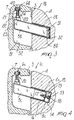
- the device according to the invention comprises a bush-like seat 2a, 2b, 2c which is formed in a face 3 of a first unit 4 and a supporting element 5a, 5b, 5c which is detachably inserted in the seat 2a, 2b, 2c and has an end which protrudes from the seat 2a, 2b, 2c and from the face 3 of the unit 4.
- the end of the supporting element 5a, 5b, 5c forms a resting region 6a, 6b, 6c for a second unit 7.
- the device comprises shock-absorbing means which are interposed between the supporting element 5a, 5b, 5c and the first unit 4 and/or between the supporting element 5a, 5b, 5c and the second unit 7.
- the supporting element 5a, 5b, 5c can be moved along the seat 2a, 2b, 2c so as to allow to vary, in a very simple manner, the distance of the resting region 6a, 6b, 6c from the face 3 of the first unit 4.
- the seat 2a, 2b, 2c is formed by a hollow body 8a, 8b, 8c which is embedded in the first unit 4, which is made of concrete, during its production and is open at the face 3 of the first unit 4.
- the seat 2a, 2b, 2c has a polygonal transverse cross-section.
- the element 5a, 5b, 5c is preferably constituted by a tubular cylindrical body which also has a polygonal transverse cross-section and can be coupled with play to the seat 2a, 2b, 2c.
- the seat 2a, 2b, 2c can extend horizontally, but preferably, in order to achieve better safety against accidental extraction of the supporting element 5a, 5b, 5c from the seat 2a, 2b, 2c during seismic events, it extends in a direction which is inclined with respect to the horizontal so that the supporting element 5a, 5b, 5c is inclined upward from its end that is inserted in the seat 2a, 2b, 2c toward its end that protrudes from the seat 2a, 2b, 2c and from the face 3 of the first unit 4.
- the portion of the supporting element 5a, 5b, 5c that protrudes from the first unit 4 is preferably accommodated in a suitable recess 51 which is formed in the second unit 7 during its production, for example by means of a box 52 made of metallic or synthetic material.
- the device according to the invention comprises first adjustment means for varying the extent of the portion of the supporting element 5a, 5c that protrudes from the seat 2a, 2c and from the face 3 of the first unit 4.
- the first adjustment means as shown in particular in Figures 1 and 2, comprise a first screw element, generally designated by the reference numeral 9, which has an adjustable useful length and is interposed between the portion of the supporting element 5a that protrudes from the seat 2a and the face 3 of the first unit 4.
- the screw element 9 has a threaded stem 10 which couples to a female thread formed inside a bush 11 which lies substantially horizontally and is fixed, for example by welding, to the end of the supporting element 5a that protrudes from the seat 2a.
- the threaded stem 10 ends, on the opposite side with respect to the bush 11, with a hexagonal head 12 which can be operated in order to turn the screw element 9 about its own axis with respect to the bush 11, so as to vary the useful length of the screw element 9.
- the first adjustment means can also be constituted by a first screw element 13 which has an adjustable useful length and is interposed between the end of the supporting element 5c that is accommodated in the seat 2c and the bottom 14 of said seat 2c.
- the screw element 13 has a threaded stem 15 which couples to a female thread formed in a plate 16 which is fixed so as to close the end of the supporting element 5c that is accommodated in the seat 2c, or to a female thread formed by a nut 17 which is welded to the side of the plate 16 that is directed toward the inside of the supporting element 5c.
- a through hole is provided in the plate 16 and is crossed by the threaded stem 15 coaxially to the threaded hole of the nut 17.
- the threaded stem 15 has, at its end that is directed toward the bottom 14 of the seat 2c, a hexagonal head 18 which can be operated in order to screw or unscrew the screw element 13, thus varying the length of the part of the screw element 13 that protrudes from the supporting element 5c and accordingly varying the extent of the portion of the supporting element 5c that protrudes from the seat 2c.
- a hexagonal head 18 which can be operated in order to screw or unscrew the screw element 13, thus varying the length of the part of the screw element 13 that protrudes from the supporting element 5c and accordingly varying the extent of the portion of the supporting element 5c that protrudes from the seat 2c.
- the device according to the invention further comprises second adjustment means for varying the elevation of the resting region 6a, 6b, 6c for the second unit 7.
- the second adjustment means comprise a second screw element 20 which is associated with the end of the supporting element 5a, 5b, 5c that protrudes from the seat 2a, 2b, 2c and from the face 3 of the first unit 4.
- the second screw element 20 extends in a substantially vertical direction and forms, with its upper end, the resting region 6a, 6b, 6c for the second unit 7.
- the screw element 20 has a variable useful length, so as to allow to vary the elevation of the resting region 6a, 6b, 6c.
- the second screw element 20 comprises a threaded stem 21 which couples to a female thread formed inside a nut or block 22 which is fixed, for example by welding, to the end of the supporting element 5a, 5b, 5c that protrudes from the seat 2a, 2b, 2c.
- a prism-shaped block 23 is provided between the nut 22 and the body of the supporting element 5a, 5b, 5c and allows the second screw element 20 to lie vertically despite the inclination of the supporting element 5a, 5b, 5c.
- the female thread with which the threaded stem 21 couples instead of being formed in a nut 22 which is fixed to the block 23, which is in turn fixed to the end of the supporting element 5a, 5b, 5c, can be formed directly inside the block 23 or the body of the supporting element 5a, 5b, 5c.
- the threaded stem 21, at its end that protrudes from the supporting element 5a, 5b, 5c, has a hexagonal head 24 which can be operated in order to turn the threaded stem 21 with respect to the female thread formed in the nut 22 or in the block 23 or in the body of the supporting element 5a, 5b, 5c in order to allow to vary the length of the portion of the threaded stem 21 that protrudes upward from the supporting element 5a, 5b, 5c.
- the first adjustment means or simply the possibility to move the supporting element with respect to the seat allow to simultaneously vary the horizontal position and the vertical position of the resting region 6.
- the vertical position of the resting region 6, determined by the movement of the supporting element 5a, 5b, 5c along the seat 2a, 2b, 2c, can then be changed by the second adjustment means.
- the shock-absorbing means in the embodiment illustrated in Figure 1, comprise a body 30 made of plastically deformable material which is interposed between the first screw element 9 and the face 3 of the first unit 4.
- the shock-absorbing means are instead constituted by a body 31 made of plastically deformable material which is interposed between the end of the supporting element 5b that is accommodated in the seat 2b and the bottom 32 of the seat 2b.
- the body 31 is fixed to the end of the supporting element 5b that is accommodated in the seat 2b; nevertheless, the body 31 might also be fixed to the bottom 32 of the seat 2b.
- the shock-absorbing means comprise a body 33 made of plastically deformable material which is interposed between the head 18 of the screw element 13 and the bottom 14 of the seat 2c.
- the shock-absorbing means also comprise a body 40 made of plastically deformable material which is interposed between the head 24 of the screw element 20 and the region of the second unit 7 that rests on the screw element 20.
- the bodies 30, 33, 40 are preferably cap-shaped and are fitted respectively on the head of the screw element 9, of the screw element 13 and of the screw element 20.
- Figure 5 is a view of a first embodiment of the bodies 30, 33, 40, according to which the surface by means of which said bodies rest respectively against the face 3 of the unit 4, against the bottom 14 of the seat 2c and against the second unit is flat.
- Figure 6 illustrates a second embodiment of the bodies, designated by the reference numerals 30a, 33a, 40a, according to which the resting surface is provided in the shape of a spherical dome.
- Figure 7 is a view of a third embodiment of the bodies, designated by the reference numerals 30b, 33b, 40b, according to which the surface has raised portions which are alternated with recesses, so as to achieve better plastic deformability for the body 30b, 33b, 40b.
- a similar configuration can also be provided for the surface of the bodies 30b, 33b and 40b that rests respectively against the head of the screw element 9, against the head of the screw element 13, and against the head of the screw element 20.
- the surface of the body 31 that rests against the bottom 32 of the seat 2b and/or the surface that rests against the supporting element 5b may be shaped like a spherical dome or may have recesses alternated with raised portions for the same purpose.
- the surfaces of the bodies, which constitute the shock-absorbing means, through which stresses are transmitted from the unit 4 to the unit 7, or vice versa preferably have a shape with raised portions alternated with recesses, so as to achieve an increase in the plastic deformability of the bodies and therefore so as to achieve a greater effect in stress damping.
- the bodies that constitute the shock-absorbing means are provided with a cap-like configuration and are fitted on the heads of the screw elements 9, 13 and 20, the lateral surface of the bodies is preferably shaped so as to have a hexagonal transverse cross-section, so as to still allow to operate the screw element 9, 13 and 20 easily even though its head is covered by the body 30, 33 and 40.
- Figure 8 illustrates an embodiment of the device according to the invention which substantially corresponds to the embodiment shown in Figure 1, the difference being that the shock-absorbing means, instead of being fitted on the head 24 of the screw element 20, are constituted by a body 50 made of plastically deformable material which is interposed between the head of the screw element 20 and the region of the second unit 7 that rests on said head.
- the body 50 can be fixed to the box 52 that is used in order to form, during the production of the second unit 7, the recess 51 in which the portion of the supporting element 5a that protrudes from the first unit 4 is accommodated.
- the first unit 4 is provided with the seat 2a, 2b, 2c, and during the installation of the units the supporting element 5a, 5b, 5c is inserted in such seat 2a, 2b, 2c.
- the second adjustment means By acting on the first adjustment means and on the second adjustment means it is possible to vary the distance of the resting region 6a, 6b, 6c from the face 3 of the first unit 4 and the elevation of the resting region 6a. In this manner, the second unit 7 that is rested on the resting region 6a, 6b, 6c can be positioned correctly with respect to the first unit 4.
- the waves and therefore the stresses that propagate from the first unit 4 to the second unit 7, if the first unit 4 is a supporting unit and the second unit 7 is a supported unit, or vice versa, are reduced significantly by the presence of the shock-absorbing means which, thanks to their plastic deformability, partially or fully absorb the stresses, interrupting their transmission.
- shock-absorbing means constituted by the bodies 30, 30a, 30b, 31 and 33, 33a, 33b, while if only vertical stresses are to be damped, it is possible to use only the shock-absorbing means constituted by the body 40, 40a, 40b or by the body 50.
- Figure 8 also illustrates braces 55 for increasing the anchoring of the cylindrical body 8b inside the first unit 4.
- the plastically deformable material used to produce the bodies 30, 31, 33 and 40 can be constituted by a synthetic material, for example the material known commercially by the trademark Nylon, or the material known commercially by the trademark Teflon, or other materials which are in any case capable of ensuring the plastic deformability of the bodies 30, 30a, 30b, 31, 33, 33a, 33b, 40, 40a, 40b in case of seismic activity.
- a synthetic material for example the material known commercially by the trademark Nylon, or the material known commercially by the trademark Teflon, or other materials which are in any case capable of ensuring the plastic deformability of the bodies 30, 30a, 30b, 31, 33, 33a, 33b, 40, 40a, 40b in case of seismic activity.
- the device according to the invention fully achieves the intended aim and objects, since the shock-absorbing means effectively eliminate or substantially reduce the transmission of the stresses produced by seismic activity between the two units that are mutually connected by the device.
- Another advantage of the device according to the invention is that it allows to adjust the position of one unit with respect to the other in a very simple and precise manner.
- the materials used may be any according to requirements and to the state of the art.
Landscapes
- Engineering & Computer Science (AREA)
- Architecture (AREA)
- Civil Engineering (AREA)
- Structural Engineering (AREA)
- Physics & Mathematics (AREA)
- Electromagnetism (AREA)
- Buildings Adapted To Withstand Abnormal External Influences (AREA)
- Vibration Prevention Devices (AREA)
- Vibration Dampers (AREA)
Claims (23)
- Eine Stützvorrichtung für vorgefertigte Gebäude-Komponenten, insbesondere für vorgefertigte Einheiten aus Beton oder ähnlichem, die einen buchsenähnlichen Sitz (2a, 2b, 2c) umfasst, der in einer Seite (3) einer ersten Einheit (4) ausgebildet ist, und ein Stützelement (5a, 5b, 5c), das lösbar in den Sitz eingesetzt ist und ein Ende hat, das aus dem Sitz (2a, 2b, 2c) und aus der Seite (3) der ersten Einheit (4) herausragt und einen Auflagebereich (6a, 6b, 6c) für eine zweite Einheit (7) bildet, dadurch gekennzeichnet, dass sie stoßdämpfende Mittel (30, 31, 33, 40, 50) umfasst, die zwischen dem Stützelement (5a, 5b, 5c) und der ersten Einheit (4) und zwischen dem Stützelement (5a, 5b, 5c) und der zweiten Einheit (7) angebracht sind.
- Die Vorrichtung gemäß Anspruch 1, dadurch gekennzeichnet, dass das Stützelement (5a, 5b, 5c) entlang dem Sitz (2a, 2b, 2c) bewegt werden kann, um den Abstand des Auflagebereichs (6a, 6b, 6c) von der Seite der ersten Einheit (4) zu variieren.
- Die Vorrichtung gemäß Anspruch 1, dadurch gekennzeichnet, dass der Sitz (2a, 2b, 2c) und das Stützelement (5a, 5b, 5c) in einem Winkel zur Horizontalen liegen, wobei das Stützelement von seinem Ende, das in den Sitz aufgenommen wird, zu seinem Ende, das aus dem Sitz und aus der Seite (3) der ersten Einheit (4) herausragt, nach oben schräg ist.
- Die Vorrichtung gemäß Anspruch 1, dadurch gekennzeichnet, dass sie erste Einstellmittel (9, 13) zur Variierung der Länge eines Abschnitts des Stützelements (5a, 5b, 5c) umfasst, das aus dem Sitz und aus der Seite der ersten Einheit (4) herausragt.
- Die Vorrichtung gemäß Anspruch 4, dadurch gekennzeichnet, dass sie zweite Einstellmittel (20) zur Variierung der Höhe des Auflagebereichs für die zweite Einheit (7) umfasst.
- Die Vorrichtung gemäß Anspruch 1, dadurch gekennzeichnet, dass der Sitz (2a, 2b, 2c) einen polygonalen transversalen Querschnitt hat und dass das Stützelement (5a, 5b, 5c) eine im wesentlichen zylindrische Form mit einem polygonalen transversalen Querschnitt hat, der mit Spiel mit dem Sitz verbunden werden kann.
- Die Vorrichtung gemäß Anspruch 1, dadurch gekennzeichnet, dass der Sitz (2a, 2b, 2c) aus einem hohlen Körper (8a, 8b, 8c) gebildet wird, der in die erste Einheit (4) eingebettet und an der Seite (3) der ersten Einheit offen ist.
- Die Vorrichtung gemäß Anspruch 1, dadurch gekennzeichnet, dass das Stützelement (5a, 5b, 5c) einen röhrenförmigen Körper hat.
- Die Vorrichtung gemäß Anspruch 1, dadurch gekennzeichnet, dass das Ende des Stützelements (5a, 5b, 5c), das aus dem Sitz und aus der Seite der ersten Einheit herausragt, in eine Vertiefung (51) aufgenommen werden kann, die in der zweiten Einheit (7) ausgebildet ist.
- Die Vorrichtung gemäß Anspruch 4, dadurch gekennzeichnet, dass das erste Einstellmittel ein erstes Schrauben-Element umfasst, das eine einstellbare nützliche Länge hat und das zwischen dem Abschnitt des Stützelements, der aus dem Sitz herausragt, und der Seite der ersten Einheit angebracht ist.
- Die Vorrichtung gemäß Anspruch 4, dadurch gekennzeichnet, dass das erste Einstellmittel (9, 13) ein erstes Schrauben-Element (9, 13) umfasst, das eine einstellbare nützliche Länge hat und das zwischen dem Ende des Stützelements (5a, 5b, 5c), das in den Sitz aufgenommen wird, und dem Boden des Sitzes angebracht wird.
- Die Vorrichtung gemäß Anspruch 5, dadurch gekennzeichnet, dass das zweite Einstellmittel (20) ein zweites Schrauben-Element (20) umfasst, das mit dem Ende des Stützelements (5a, 5b, 5c) verbunden ist, welches aus dem Sitz (2a, 2b, 2c) und aus der Seite (3) der ersten Einheit (4) herausragt, wobei das zweite Schrauben-Element (20) in einer im wesentlichen vertikalen Richtung angeordnet ist und mit einem oberen Ende davon den Auflagebereich für die zweite Einheit bildet, wobei das Schrauben-Element eine nützliche Länge hat, die variieren kann, um die Höhe des Auflagebereichs (6a, 6b, 6c) zu variieren.
- Die Vorrichtung gemäß Anspruch 10, dadurch gekennzeichnet, dass das stoßdämpfende Mittel einen Körper (30) aus plastisch verformbarem Material umfasst, der zwischen dem ersten Schrauben-Element (9) und der Seite (3) der ersten Einheit (4) angebracht ist.
- Die Vorrichtung gemäß Anspruch 11, dadurch gekennzeichnet, dass das stoßdämpfende Mittel einen Körper (31) aus plastisch verformbarem Material umfasst, der zwischen dem Ende des Stützelements (5b), das in den Sitz (2b) aufgenommen wird, und dem Boden (32) des Sitzes (2b) angebracht wird.
- Die Vorrichtung gemäß Anspruch 10, dadurch gekennzeichnet, dass das stoßdämpfende Mittel einen Körper (33) aus plastisch verformbarem Material umfasst, der zwischen dem ersten Schrauben-Element (13) und dem Boden (14) des Sitzes (2c) angebracht ist.
- Die Vorrichtung gemäß Anspruch 12, dadurch gekennzeichnet, dass das stoßdämpfende Mittel einen Körper (40) aus plastisch verformbarem Material umfasst, der zwischen dem Auflagebereich, der vom Stützelement gebildet wird, und der zweiten Einheit (7) angebracht ist.
- Die Vorrichtung gemäß Anspruch 13, dadurch gekennzeichnet, dass der Körper (30) aus plastisch verformbarem Material kappenförmig ist und auf das Ende des ersten Schrauben-Elements (9) eingepasst wird, das in die Seite (3) der ersten Einheit (4) eingreift.
- Die Vorrichtung gemäß Anspruch 14, dadurch gekennzeichnet, dass der Körper (33) aus plastisch verformbarem Material kappenförmig ist und auf das Ende des ersten Schrauben-Elements (13) eingepasst wird, das in den Boden (14) des Sitzes (2c) eingreift.
- Die Vorrichtung gemäß Anspruch 16, dadurch gekennzeichnet, dass der Körper (40) aus plastisch verformbarem Material kappenförmig ist und auf das Ende des zweiten Schrauben-Elements (20) eingepasst wird, das den Auflagebereich für die zweite Einheit bildet.
- Die Vorrichtung gemäß Anspruch 12, dadurch gekennzeichnet, dass der Körper (50) aus plastisch verformbarem Material in dem Bereich einer Vertiefung (51) der zweiten Einheit angebracht ist, der auf dem Auflagebereich, der vom Stützelement gebildet wird, ruhen soll.
- Die Vorrichtung gemäß Anspruch 11, dadurch gekennzeichnet, dass der Körper aus plastisch verformbarem Material an dem Ende des Stützelements angebracht wird, das zum Boden des Sitzes hin gerichtet ist.
- Die Vorrichtung gemäß einem oder mehreren der obigen Ansprüche, dadurch gekennzeichnet, dass mindestens eine der Oberflächen des plastisch verformbaren Körpers, die in Kontakt mit der ersten Einheit (4) oder mit der zweiten Einheit (7) oder mit dem Boden des Sitzes oder mit dem Stützelement oder mit dem Einstellmittel steht, erhobene Abschnitte hat, die mit Vertiefungen abwechseln, um die plastische Verformbarkeit des plastisch verformbaren Körpers zu erhöhen.
- Die Vorrichtung gemäß einem oder mehreren der obigen Ansprüche, dadurch gekennzeichnet, dass die Oberfläche des plastisch verformbaren Körpers, die im Kontakt mit der ersten Einheit (4) oder mit der zweiten Einheit (7) oder mit dem Boden des Sitzes oder mit dem Stützelement oder mit dem Einstellmittel steht, kuppelförmig ist.
Priority Applications (5)
| Application Number | Priority Date | Filing Date | Title |
|---|---|---|---|
| AT00110239T ATE309424T1 (de) | 2000-05-19 | 2000-05-19 | Stützvorrichtung für vorgefertigt, insbesondere aus beton oder ähnlichem, hergestellte gebäudeteile mit hohem widerstand gegen erdbeben |
| EP00110239A EP1156169B1 (de) | 2000-05-19 | 2000-05-19 | Stützvorrichtung für vorgefertigt, insbesondere aus Beton oder ähnlichem, hergestellte Gebäudeteile mit hohem Widerstand gegen Erdbeben |
| ES00110239T ES2251907T3 (es) | 2000-05-19 | 2000-05-19 | Dispositivo de soporte para componentes de construccion prefabricados hechas de hormigon o similars, con una elevada resistencia a los terremotos. |
| DE60023848T DE60023848D1 (de) | 2000-05-19 | 2000-05-19 | Stützvorrichtung für vorgefertigt, insbesondere aus Beton oder ähnlichem, hergestellte Gebäudeteile mit hohem Widerstand gegen Erdbeben |
| US09/576,132 US6339903B1 (en) | 2000-05-19 | 2000-05-22 | Supporting device for prefabricated building components, particularly for prefabricated units made of concrete or the like, with high resistance to earthquakes |
Applications Claiming Priority (2)
| Application Number | Priority Date | Filing Date | Title |
|---|---|---|---|
| EP00110239A EP1156169B1 (de) | 2000-05-19 | 2000-05-19 | Stützvorrichtung für vorgefertigt, insbesondere aus Beton oder ähnlichem, hergestellte Gebäudeteile mit hohem Widerstand gegen Erdbeben |
| US09/576,132 US6339903B1 (en) | 2000-05-19 | 2000-05-22 | Supporting device for prefabricated building components, particularly for prefabricated units made of concrete or the like, with high resistance to earthquakes |
Publications (2)
| Publication Number | Publication Date |
|---|---|
| EP1156169A1 EP1156169A1 (de) | 2001-11-21 |
| EP1156169B1 true EP1156169B1 (de) | 2005-11-09 |
Family
ID=26070937
Family Applications (1)
| Application Number | Title | Priority Date | Filing Date |
|---|---|---|---|
| EP00110239A Expired - Lifetime EP1156169B1 (de) | 2000-05-19 | 2000-05-19 | Stützvorrichtung für vorgefertigt, insbesondere aus Beton oder ähnlichem, hergestellte Gebäudeteile mit hohem Widerstand gegen Erdbeben |
Country Status (5)
| Country | Link |
|---|---|
| US (1) | US6339903B1 (de) |
| EP (1) | EP1156169B1 (de) |
| AT (1) | ATE309424T1 (de) |
| DE (1) | DE60023848D1 (de) |
| ES (1) | ES2251907T3 (de) |
Families Citing this family (7)
| Publication number | Priority date | Publication date | Assignee | Title |
|---|---|---|---|---|
| ITMI20010777A1 (it) * | 2001-04-11 | 2002-10-11 | Ruredil Spa | Dispositivo di sostegno ruotante per elementi prefabbricati |
| US7765764B2 (en) * | 2005-08-08 | 2010-08-03 | Sergio Zambelli | Device for connecting beams and pillars or similar structural elements |
| US8011147B2 (en) * | 2006-09-11 | 2011-09-06 | Hanlon John W | Building system using modular precast concrete components |
| US8359793B2 (en) | 2010-08-26 | 2013-01-29 | Danny Chagai Zeevi | Earthquake force absorption system |
| NL2006000C2 (nl) * | 2011-01-13 | 2012-07-17 | Transwelding C V | Werkwijze voor het bevestigen van een plaat aan een diepwand, alsmede voor het stutten van een diepwand. |
| US9840842B2 (en) | 2015-05-04 | 2017-12-12 | Willis Construction Company, Inc | Apparatus and methods of precast architectural panel connections |
| KR102078985B1 (ko) * | 2017-12-27 | 2020-02-19 | 한국전력공사 | 내진 보강용 댐퍼 |
Family Cites Families (6)
| Publication number | Priority date | Publication date | Assignee | Title |
|---|---|---|---|---|
| DE3117547A1 (de) * | 1981-05-04 | 1982-11-18 | Hilti AG, 9494 Schaan | Vorrichtung zur halterung von verkleidungsplatten u.dgl. an bauwerksteilen |
| DE3206099A1 (de) * | 1982-02-19 | 1983-09-01 | Marbeton Kies- U. Betonwerk Marstetten Gmbh, 7971 Aitrach | Auflagerelement in bewehrten betonplatten |
| US4523413A (en) * | 1983-03-18 | 1985-06-18 | Koppenberg Bruce G | Hanger fastener |
| US4583336A (en) * | 1984-10-29 | 1986-04-22 | The Austin Company | Joint of preformed concrete elements |
| IT1236955B (it) | 1989-10-16 | 1993-05-07 | Sergio Zambelli | Dispositivo di sostegno e di ancoraggio a secco per manufatti prefabbricati, in particolare in calcestruzzo o simili. |
| IT224173Z2 (it) * | 1991-01-18 | 1996-02-09 | Fischer Italia Di Paolo Morasu | Elemento adattatore per dispositivi di ancoraggio di lastre per il rivestimento di pareti |
-
2000
- 2000-05-19 DE DE60023848T patent/DE60023848D1/de not_active Expired - Lifetime
- 2000-05-19 ES ES00110239T patent/ES2251907T3/es not_active Expired - Lifetime
- 2000-05-19 EP EP00110239A patent/EP1156169B1/de not_active Expired - Lifetime
- 2000-05-19 AT AT00110239T patent/ATE309424T1/de not_active IP Right Cessation
- 2000-05-22 US US09/576,132 patent/US6339903B1/en not_active Expired - Fee Related
Also Published As
| Publication number | Publication date |
|---|---|
| EP1156169A1 (de) | 2001-11-21 |
| US6339903B1 (en) | 2002-01-22 |
| ES2251907T3 (es) | 2006-05-16 |
| DE60023848D1 (de) | 2005-12-15 |
| ATE309424T1 (de) | 2005-11-15 |
Similar Documents
| Publication | Publication Date | Title |
|---|---|---|
| EP1156170B1 (de) | Stützvorrichtung für vorgefertigte Teile, insbesondere für Konstruktionen mit einer Metallstruktur | |
| US4056903A (en) | Wall support mechanism for adjusting the vertical orientation and height of a wall member | |
| KR102230607B1 (ko) | 내진형 석재 고정장치 | |
| EP1156169B1 (de) | Stützvorrichtung für vorgefertigt, insbesondere aus Beton oder ähnlichem, hergestellte Gebäudeteile mit hohem Widerstand gegen Erdbeben | |
| KR20200109512A (ko) | 내진 유리 커튼 월 고정장치 및 이를 포함하는 내진 유리 커튼 월 시스템 | |
| KR102061497B1 (ko) | 내진 기능을 갖는 물탱크 지지장치 | |
| KR20160121880A (ko) | 맨홀프레임의 높이 및 경사 조절이 가능한 맨홀 | |
| KR20200015224A (ko) | 높이 및 경사 조절식 맨홀 | |
| JP2002294853A (ja) | 排水桝 | |
| KR102032122B1 (ko) | 높이조절이 가능한 물탱크의 기초장치 | |
| KR102503438B1 (ko) | 기울기 보정 기능이 있는 퍼걸러 | |
| KR20190076577A (ko) | 높이와 수평조절이 용이한 물탱크용 기초패드 | |
| EP0423660B1 (de) | Stütz- und Verankerungsvorrichtung für vorgefertigte, insbesondere aus Beton oder ähnlichem hergestellte Gebäudeteile | |
| KR200228439Y1 (ko) | 강 유닛용 기저부 | |
| JPH11166331A (ja) | 免震引抜抵抗装置 | |
| JP4313741B2 (ja) | 墓石の免震装置及び免震装置を備えた墓石 | |
| KR200231056Y1 (ko) | 충격하중 흡수식 교좌장치 | |
| KR101857077B1 (ko) | 아치형 건물의 지주 설치 고정용 고정유닛 및 그 고정유닛을 이용한 지주 설치 고정방법 | |
| KR102925064B1 (ko) | 슬립 조인트 암 체결구조가 적용된 가로등주 | |
| KR200384367Y1 (ko) | 건축용 서포트 | |
| KR102570994B1 (ko) | 내진 기능을 가지는 브릿지 기둥 및 그 시공방법 | |
| CN220891305U (zh) | 一种建筑给排水结构 | |
| KR101773778B1 (ko) | 옥외 지주용 진동방지장치 | |
| JP3187640B2 (ja) | 壁体パネルの取付方法、及び、その取付金具 | |
| KR102949425B1 (ko) | 벽걸이형 티브이 고정장치 |
Legal Events
| Date | Code | Title | Description |
|---|---|---|---|
| PUAI | Public reference made under article 153(3) epc to a published international application that has entered the european phase |
Free format text: ORIGINAL CODE: 0009012 |
|
| AK | Designated contracting states |
Kind code of ref document: A1 Designated state(s): AT BE CH CY DE DK ES FI FR GB GR IE IT LI LU MC NL PT SE |
|
| AX | Request for extension of the european patent |
Free format text: AL;LT;LV;MK;RO;SI |
|
| 17P | Request for examination filed |
Effective date: 20020425 |
|
| AKX | Designation fees paid |
Free format text: AT BE CH CY DE DK ES FI FR GB GR IE IT LI LU MC NL PT SE |
|
| 17Q | First examination report despatched |
Effective date: 20040722 |
|
| GRAP | Despatch of communication of intention to grant a patent |
Free format text: ORIGINAL CODE: EPIDOSNIGR1 |
|
| GRAS | Grant fee paid |
Free format text: ORIGINAL CODE: EPIDOSNIGR3 |
|
| GRAA | (expected) grant |
Free format text: ORIGINAL CODE: 0009210 |
|
| AK | Designated contracting states |
Kind code of ref document: B1 Designated state(s): AT BE CH CY DE DK ES FI FR GB GR IE IT LI LU MC NL PT SE |
|
| PG25 | Lapsed in a contracting state [announced via postgrant information from national office to epo] |
Ref country code: FI Free format text: LAPSE BECAUSE OF FAILURE TO SUBMIT A TRANSLATION OF THE DESCRIPTION OR TO PAY THE FEE WITHIN THE PRESCRIBED TIME-LIMIT Effective date: 20051109 Ref country code: CH Free format text: LAPSE BECAUSE OF FAILURE TO SUBMIT A TRANSLATION OF THE DESCRIPTION OR TO PAY THE FEE WITHIN THE PRESCRIBED TIME-LIMIT Effective date: 20051109 Ref country code: AT Free format text: LAPSE BECAUSE OF FAILURE TO SUBMIT A TRANSLATION OF THE DESCRIPTION OR TO PAY THE FEE WITHIN THE PRESCRIBED TIME-LIMIT Effective date: 20051109 Ref country code: NL Free format text: LAPSE BECAUSE OF FAILURE TO SUBMIT A TRANSLATION OF THE DESCRIPTION OR TO PAY THE FEE WITHIN THE PRESCRIBED TIME-LIMIT Effective date: 20051109 Ref country code: LI Free format text: LAPSE BECAUSE OF FAILURE TO SUBMIT A TRANSLATION OF THE DESCRIPTION OR TO PAY THE FEE WITHIN THE PRESCRIBED TIME-LIMIT Effective date: 20051109 Ref country code: BE Free format text: LAPSE BECAUSE OF FAILURE TO SUBMIT A TRANSLATION OF THE DESCRIPTION OR TO PAY THE FEE WITHIN THE PRESCRIBED TIME-LIMIT Effective date: 20051109 |
|
| REG | Reference to a national code |
Ref country code: GB Ref legal event code: FG4D |
|
| REG | Reference to a national code |
Ref country code: CH Ref legal event code: EP |
|
| REG | Reference to a national code |
Ref country code: IE Ref legal event code: FG4D |
|
| REF | Corresponds to: |
Ref document number: 60023848 Country of ref document: DE Date of ref document: 20051215 Kind code of ref document: P |
|
| PG25 | Lapsed in a contracting state [announced via postgrant information from national office to epo] |
Ref country code: DK Free format text: LAPSE BECAUSE OF FAILURE TO SUBMIT A TRANSLATION OF THE DESCRIPTION OR TO PAY THE FEE WITHIN THE PRESCRIBED TIME-LIMIT Effective date: 20060209 Ref country code: GR Free format text: LAPSE BECAUSE OF FAILURE TO SUBMIT A TRANSLATION OF THE DESCRIPTION OR TO PAY THE FEE WITHIN THE PRESCRIBED TIME-LIMIT Effective date: 20060209 Ref country code: SE Free format text: LAPSE BECAUSE OF FAILURE TO SUBMIT A TRANSLATION OF THE DESCRIPTION OR TO PAY THE FEE WITHIN THE PRESCRIBED TIME-LIMIT Effective date: 20060209 |
|
| PG25 | Lapsed in a contracting state [announced via postgrant information from national office to epo] |
Ref country code: DE Free format text: LAPSE BECAUSE OF FAILURE TO SUBMIT A TRANSLATION OF THE DESCRIPTION OR TO PAY THE FEE WITHIN THE PRESCRIBED TIME-LIMIT Effective date: 20060210 |
|
| PG25 | Lapsed in a contracting state [announced via postgrant information from national office to epo] |
Ref country code: PT Free format text: LAPSE BECAUSE OF FAILURE TO SUBMIT A TRANSLATION OF THE DESCRIPTION OR TO PAY THE FEE WITHIN THE PRESCRIBED TIME-LIMIT Effective date: 20060410 |
|
| NLV1 | Nl: lapsed or annulled due to failure to fulfill the requirements of art. 29p and 29m of the patents act | ||
| REG | Reference to a national code |
Ref country code: ES Ref legal event code: FG2A Ref document number: 2251907 Country of ref document: ES Kind code of ref document: T3 |
|
| PG25 | Lapsed in a contracting state [announced via postgrant information from national office to epo] |
Ref country code: IE Free format text: LAPSE BECAUSE OF NON-PAYMENT OF DUE FEES Effective date: 20060519 Ref country code: GB Free format text: LAPSE BECAUSE OF NON-PAYMENT OF DUE FEES Effective date: 20060519 |
|
| PG25 | Lapsed in a contracting state [announced via postgrant information from national office to epo] |
Ref country code: MC Free format text: LAPSE BECAUSE OF NON-PAYMENT OF DUE FEES Effective date: 20060531 |
|
| REG | Reference to a national code |
Ref country code: CH Ref legal event code: PL |
|
| ET | Fr: translation filed | ||
| PLBE | No opposition filed within time limit |
Free format text: ORIGINAL CODE: 0009261 |
|
| STAA | Information on the status of an ep patent application or granted ep patent |
Free format text: STATUS: NO OPPOSITION FILED WITHIN TIME LIMIT |
|
| 26N | No opposition filed |
Effective date: 20060810 |
|
| GBPC | Gb: european patent ceased through non-payment of renewal fee |
Effective date: 20060519 |
|
| REG | Reference to a national code |
Ref country code: IE Ref legal event code: MM4A |
|
| PG25 | Lapsed in a contracting state [announced via postgrant information from national office to epo] |
Ref country code: LU Free format text: LAPSE BECAUSE OF NON-PAYMENT OF DUE FEES Effective date: 20060519 |
|
| PG25 | Lapsed in a contracting state [announced via postgrant information from national office to epo] |
Ref country code: CY Free format text: LAPSE BECAUSE OF FAILURE TO SUBMIT A TRANSLATION OF THE DESCRIPTION OR TO PAY THE FEE WITHIN THE PRESCRIBED TIME-LIMIT Effective date: 20051109 |
|
| PGFP | Annual fee paid to national office [announced via postgrant information from national office to epo] |
Ref country code: FR Payment date: 20100622 Year of fee payment: 11 |
|
| PGFP | Annual fee paid to national office [announced via postgrant information from national office to epo] |
Ref country code: ES Payment date: 20110519 Year of fee payment: 12 |
|
| REG | Reference to a national code |
Ref country code: FR Ref legal event code: ST Effective date: 20120131 |
|
| PG25 | Lapsed in a contracting state [announced via postgrant information from national office to epo] |
Ref country code: FR Free format text: LAPSE BECAUSE OF NON-PAYMENT OF DUE FEES Effective date: 20110531 |
|
| PGFP | Annual fee paid to national office [announced via postgrant information from national office to epo] |
Ref country code: IT Payment date: 20130522 Year of fee payment: 14 |
|
| REG | Reference to a national code |
Ref country code: ES Ref legal event code: FD2A Effective date: 20131030 |
|
| PG25 | Lapsed in a contracting state [announced via postgrant information from national office to epo] |
Ref country code: ES Free format text: LAPSE BECAUSE OF NON-PAYMENT OF DUE FEES Effective date: 20120520 |
|
| PG25 | Lapsed in a contracting state [announced via postgrant information from national office to epo] |
Ref country code: IT Free format text: LAPSE BECAUSE OF NON-PAYMENT OF DUE FEES Effective date: 20140519 |