EP1156256A2 - Anneau de serrage - Google Patents
Anneau de serrage Download PDFInfo
- Publication number
- EP1156256A2 EP1156256A2 EP01104668A EP01104668A EP1156256A2 EP 1156256 A2 EP1156256 A2 EP 1156256A2 EP 01104668 A EP01104668 A EP 01104668A EP 01104668 A EP01104668 A EP 01104668A EP 1156256 A2 EP1156256 A2 EP 1156256A2
- Authority
- EP
- European Patent Office
- Prior art keywords
- clamping ring
- segments
- bracket
- lever
- ring according
- Prior art date
- Legal status (The legal status is an assumption and is not a legal conclusion. Google has not performed a legal analysis and makes no representation as to the accuracy of the status listed.)
- Granted
Links
Images

Classifications
-
- F—MECHANICAL ENGINEERING; LIGHTING; HEATING; WEAPONS; BLASTING
- F16—ENGINEERING ELEMENTS AND UNITS; GENERAL MEASURES FOR PRODUCING AND MAINTAINING EFFECTIVE FUNCTIONING OF MACHINES OR INSTALLATIONS; THERMAL INSULATION IN GENERAL
- F16L—PIPES; JOINTS OR FITTINGS FOR PIPES; SUPPORTS FOR PIPES, CABLES OR PROTECTIVE TUBING; MEANS FOR THERMAL INSULATION IN GENERAL
- F16L23/00—Flanged joints
- F16L23/04—Flanged joints the flanges being connected by members tensioned in the radial plane
- F16L23/08—Flanged joints the flanges being connected by members tensioned in the radial plane connection by tangentially arranged pin and nut
- F16L23/10—Flanged joints the flanges being connected by members tensioned in the radial plane connection by tangentially arranged pin and nut with a pivoting or swinging pin
-
- F—MECHANICAL ENGINEERING; LIGHTING; HEATING; WEAPONS; BLASTING
- F16—ENGINEERING ELEMENTS AND UNITS; GENERAL MEASURES FOR PRODUCING AND MAINTAINING EFFECTIVE FUNCTIONING OF MACHINES OR INSTALLATIONS; THERMAL INSULATION IN GENERAL
- F16L—PIPES; JOINTS OR FITTINGS FOR PIPES; SUPPORTS FOR PIPES, CABLES OR PROTECTIVE TUBING; MEANS FOR THERMAL INSULATION IN GENERAL
- F16L23/00—Flanged joints
- F16L23/04—Flanged joints the flanges being connected by members tensioned in the radial plane
- F16L23/06—Flanged joints the flanges being connected by members tensioned in the radial plane connected by toggle-action levers
-
- Y—GENERAL TAGGING OF NEW TECHNOLOGICAL DEVELOPMENTS; GENERAL TAGGING OF CROSS-SECTIONAL TECHNOLOGIES SPANNING OVER SEVERAL SECTIONS OF THE IPC; TECHNICAL SUBJECTS COVERED BY FORMER USPC CROSS-REFERENCE ART COLLECTIONS [XRACs] AND DIGESTS
- Y10—TECHNICAL SUBJECTS COVERED BY FORMER USPC
- Y10T—TECHNICAL SUBJECTS COVERED BY FORMER US CLASSIFICATION
- Y10T24/00—Buckles, buttons, clasps, etc.
- Y10T24/14—Bale and package ties, hose clamps
- Y10T24/1412—Bale and package ties, hose clamps with tighteners
- Y10T24/1418—Self-locking [dead center or snap action]
- Y10T24/142—Adjustable girth
-
- Y—GENERAL TAGGING OF NEW TECHNOLOGICAL DEVELOPMENTS; GENERAL TAGGING OF CROSS-SECTIONAL TECHNOLOGIES SPANNING OVER SEVERAL SECTIONS OF THE IPC; TECHNICAL SUBJECTS COVERED BY FORMER USPC CROSS-REFERENCE ART COLLECTIONS [XRACs] AND DIGESTS
- Y10—TECHNICAL SUBJECTS COVERED BY FORMER USPC
- Y10T—TECHNICAL SUBJECTS COVERED BY FORMER US CLASSIFICATION
- Y10T24/00—Buckles, buttons, clasps, etc.
- Y10T24/14—Bale and package ties, hose clamps
- Y10T24/1412—Bale and package ties, hose clamps with tighteners
- Y10T24/1424—Lever
Definitions
- the present invention relates to a clamping ring, in particular for connecting two pipe ends, with a ring-shaped receptacle made up of several together hinged segments is formed, and a closure device by means of two segments are releasably connectable.
- Clamping rings have already been proposed which are articulated with two to one another connected segments are formed and on the opposite of the joint Side can be clamped together by means of a closure device.
- the locking device is designed in the manner of a quick lock, at which can be clamped together using a lever, so no assembly tools are required.
- an adjusting element on the closure device for example in the form of a screw, which can be screwed into a hinge pin is, so that when the closure device is opened, the adjustment device an adjustment of the clamping force by adjusting the position of the segments of the Collet allows each other.
- Such a clamping ring has the disadvantage that the mounting of the clamping ring is relative is complex because the locking device each time to adjust the clamping force must be opened and closed again. So the setting is made step by step until the desired tension is reached. This fine adjustment is therefore relatively tedious, precisely because the adjustment path to be set is usually small is. There is a direct adjustment of the clamping ring when closed mostly not intended or difficult to do because this area is difficult to access is.
- a clamping ring of the type mentioned at the position of the at least one joint element between two segments Segments is adjustable relative to each other.
- the clamping ring can be easily be tensioned after assembly.
- the clamping ring can be set so that by means of the closure device a pre-fixation / pre-tensioning of the to be connected Tube parts is reached, so that re-tensioning without holding the Clamping ring can be done. This greatly simplifies assembly as the operations assembly of the clamping ring on the pipe ends and retensioning in completely separate steps can take place. It is also retensioned Condition an unauthorized loosening of the voltage connection without tools not possible.
- an adjustment device for stepless adjustment of the two articulated segments provided so that the adjustment of the clamping force is particularly sensitive can.
- the adjustment device can be inserted into a hinge pin screw or other suitable means.
- a simple clamping ring with few components has two segments, on one side via the adjustable joint element and on the opposite Side are connected to each other via the closure device.
- the closure device preferably has a bracket, which is attached to one engages the first segment provided projection.
- This type of locking device can be easily assembled because the bracket only folds over the projection to connect the two segments.
- the bracket can be articulated with one on a second Segment articulated lever be connected so that the lever movement two segments are pulled together.
- the bracket is preferred held interchangeably on the lever. This can be used to connect Pipe ends with different diameters or different sealants a suitable bracket can be mounted on the clamping ring without the rest Elements of the clamping ring would have to be replaced.
- the lever can also be exchanged or several Have holes so that the hinge pin of the bracket in different Holes can be mounted.
- the bracket is in the pivoting direction guided on a side surface of the lever.
- the bracket is through a bolt connected to the lever.
- the guide of the bracket on the side surfaces of the lever and / or additionally ensures on the side surfaces of the projection straight swivel movement, even if the hinge pin is taken up with play in the bracket is. If the bracket also fits the projection positively, the provision of the necessary elasticity is achieved.
- the closure device is with a second adjustment device for subsequent adjustment of the position provided two segments relative to each other.
- a second adjustment device for subsequent adjustment of the position provided two segments relative to each other. This allows the area between increased the maximum and minimum receiving diameter of the clamping ring because both adjustment devices complement each other.
- this is preferably through a screw is screwed into the bracket. The bracket or bracket and lever can be exchanged retrospectively with the bracket without adjustment if necessary.
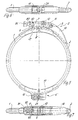
- the clamping ring shown in FIGS. 1 to 4 has a first segment 1 and second segment 2.
- the two segments 1 and 2 are on one side with a Closure device 3 and on the other side via a joint element 4 with each other connected.
- the segments 1 and 2 are essentially U-shaped Cross-section (Fig. 4) with sloping legs, so that two pipe flanges with sealants in segments 1 and 2 can be accommodated are and by moving segments 1 and 2 together the pipe ends tight pressed together.
- the segment 1 is surrounded by a profile 5 in the area of the closure device, that is welded to the segment.
- the profile 5 has two protruding Side walls 6, which has a contact surface 7 for engagement with a bracket Own 8.
- the bracket 8 is articulated on an axis 9 with a lever 10, which in turn is articulated on an axis 11 on a projection 12.
- the segment 2 is surrounded by a profile 13 in the area of the closure device, on which the projection 12 is formed.
- the bracket 8 has in its front Area on a web 14, which rests on the contact surface 7.
- the investment point of the bracket 8, the axis 9 and the axis 11 form a triangle, so that when closing the lever 10, the dead center of the locking device is slightly exceeded is and the lever 10 on the clamping forces in the closed position is kept safe.
- the lever 10 lies against the end of the grip area 24 segment 2.
- a joint element 4 is provided, which Segments 1 and 2 are articulated together.
- segment 1 is permanent connected to a profile 15 on which a projection 18 is formed.
- the segment 2 is surrounded by a profile 16 on which a Projection 20 is formed.
- a hinge pin 19 is received in the projection 18, which is provided with a threaded hole.
- a screw 21 screwed in the area of the head on a wall of the projection 20 is present.
- a second embodiment of a clamping ring is shown, the same components as in the first embodiment with the same Reference numbers are marked.
- This tension ring is between the A joint element 4 'is provided for segments 1 and 2.
- the joint element is in operation 4 'identical to the joint element 4.
- a closure device 3 ' is provided on the opposite side, in which a bracket 8 'is articulated via an axis 9 to a lever 10, which in turn is articulated to segment 2 on an axis 11.
- the Bracket 8 ' has a web 80 at its end, in which a threaded bore is spared.
- a screw 81 is screwed into the threaded bore Front carries a rounded disc 82.
- the disk 82 lies on the rounded one Contact surface 7 of the projection 6.
- the shape of the lever 10 is chosen so that the segment 2 at least is partially encompassed and overall a rounded as possible, optically correct Component surface represents.
- each Lever 10 there is only one opening in each Lever 10 is provided for receiving an axis 9 of the bracket 8. It is also possible, in the lever 10 to cut out several openings so that the bracket 8 on different locations in the lever 10 can be mounted. This increases the maximum adjustment range.
- the bracket 8 and / or the lever 10 is preferably interchangeable, so that the Clamping ring can be used flexibly for different applications.
- the clamping ring can be made of galvanized steel or stainless steel.
- the gap 17 between segment 1 and segment 2 is preferably in one Area provided in which the segments of a profile 5, 13, 15 or 16th are surrounded, so that a lateral fixation of the segment 1 or 2 by the each profile is reached and the inserted sealing material escapes is prevented.
- the segments 1 are adjusted and 2 each with screws with hexagon socket.
- Screws or adjustment elements such as knobs, snap or clamp connections to provide.
Landscapes
- Engineering & Computer Science (AREA)
- General Engineering & Computer Science (AREA)
- Mechanical Engineering (AREA)
- Clamps And Clips (AREA)
- Gripping Jigs, Holding Jigs, And Positioning Jigs (AREA)
- Diaphragms And Bellows (AREA)
- Quick-Acting Or Multi-Walled Pipe Joints (AREA)
- Flanged Joints, Insulating Joints, And Other Joints (AREA)
- Wire Bonding (AREA)
- Eye Examination Apparatus (AREA)
- Mutual Connection Of Rods And Tubes (AREA)
Applications Claiming Priority (2)
| Application Number | Priority Date | Filing Date | Title |
|---|---|---|---|
| DE10024834 | 2000-05-19 | ||
| DE10024834A DE10024834A1 (de) | 2000-05-19 | 2000-05-19 | Spannring |
Publications (4)
| Publication Number | Publication Date |
|---|---|
| EP1156256A2 true EP1156256A2 (fr) | 2001-11-21 |
| EP1156256A3 EP1156256A3 (fr) | 2003-01-02 |
| EP1156256B1 EP1156256B1 (fr) | 2005-09-07 |
| EP1156256B2 EP1156256B2 (fr) | 2010-08-11 |
Family
ID=7642799
Family Applications (1)
| Application Number | Title | Priority Date | Filing Date |
|---|---|---|---|
| EP01104668A Expired - Lifetime EP1156256B2 (fr) | 2000-05-19 | 2001-02-24 | Anneau de serrage |
Country Status (6)
| Country | Link |
|---|---|
| US (1) | US6470538B2 (fr) |
| EP (1) | EP1156256B2 (fr) |
| AT (1) | ATE304143T1 (fr) |
| DE (2) | DE10024834A1 (fr) |
| DK (1) | DK1156256T3 (fr) |
| MX (1) | MXPA01004955A (fr) |
Families Citing this family (24)
| Publication number | Priority date | Publication date | Assignee | Title |
|---|---|---|---|---|
| US7165789B2 (en) * | 2001-10-26 | 2007-01-23 | Salco Products, Inc. | Clamp assembly |
| US7207602B2 (en) * | 2001-10-26 | 2007-04-24 | Salco Products, Inc. | Clamp assembly |
| FR2864920B1 (fr) * | 2004-01-09 | 2006-08-04 | Bruno Leneveu | Dispositif pour l'assemblage d'elements standar destine a la realisation de structures mecaniques de precision |
| US20060090435A1 (en) * | 2004-11-01 | 2006-05-04 | Hantech Corporation | Securing and leakage prevention mechanism of filter tube |
| AT500002A1 (de) * | 2005-02-23 | 2005-10-15 | Bertrams Kg | Spannring mit schnellverschluss |
| US7562484B2 (en) * | 2006-05-16 | 2009-07-21 | Surefire, Llc | Clamp mount |
| DE102007016417B3 (de) * | 2006-10-19 | 2008-03-13 | Fr. Jacob Söhne GmbH & Co. | Erdungsbrücke für Rohrverbindunen |
| US20090084930A1 (en) * | 2007-09-28 | 2009-04-02 | Sonoco Development, Inc. | Concrete form for pouring polygonal columns |
| US8448993B2 (en) | 2009-06-12 | 2013-05-28 | Romac Industries, Inc. | Pipe coupling |
| US11274777B2 (en) | 2009-06-12 | 2022-03-15 | Romac Industries, Inc. | Pipe coupling |
| US20120068459A1 (en) * | 2010-09-16 | 2012-03-22 | Mao-Nan Cheng | Fitting ring |
| US8894100B2 (en) | 2012-03-16 | 2014-11-25 | Romac Industries, Inc. | Fitting with draw mechanism |
| JP6179264B2 (ja) * | 2013-08-09 | 2017-08-16 | ヤマハ株式会社 | 管楽器用ベル、管楽器及び縁輪 |
| US9261211B2 (en) | 2013-10-11 | 2016-02-16 | Eaton Corporation | Latching mechanisms for clamshell type couplers |
| FR3025903B1 (fr) * | 2014-09-17 | 2017-11-03 | Thales Sa | Dispositif d'entrée de données et ses moyens de freinage |
| US11054035B2 (en) | 2015-03-24 | 2021-07-06 | Quickhub, Llc | Pipe connector systems, devices and methods |
| US10253885B2 (en) | 2015-03-24 | 2019-04-09 | Quickhub, Llc | Pipe connector systems, devices and methods |
| US10557578B2 (en) | 2015-03-24 | 2020-02-11 | Quickhub, Llc | Pipe connector systems, devices and methods |
| US11073233B2 (en) | 2015-03-24 | 2021-07-27 | Quickhub, Llc | Pipe connector systems, devices and methods |
| US10100956B2 (en) | 2015-03-24 | 2018-10-16 | Quickhub, Llc | Pipe connector systems, devices and methods |
| DE112021003156T5 (de) * | 2020-06-05 | 2023-03-23 | Advanced Couplings Limited | Schnellspannschellenanordnung |
| US12379056B1 (en) | 2020-06-09 | 2025-08-05 | The United States Of America, As Represented By The Secretary Of The Navy | Dual cam lever hose clamp |
| US12078270B1 (en) | 2020-06-09 | 2024-09-03 | The United States Of America, As Represented By The Secretary Of The Navy | Dual cam lever hose clamp and methods of use thereof |
| US11585475B1 (en) * | 2020-06-09 | 2023-02-21 | The United States Of America, As Represented By The Secretary Of The Navy | Dual cam lever hose clamp |
Family Cites Families (18)
| Publication number | Priority date | Publication date | Assignee | Title |
|---|---|---|---|---|
| US265995A (en) * | 1882-10-17 | towns | ||
| DE47720C (de) * | m. bauer in Neustreüt', am Bahnhof | Schlauchbefestigungsschelle mit Kniehebelanzug und Sperrstift | ||
| DE47220C (de) | J. GRÖGER in Wien V., Margarethenstr. 35 | Musterschneidemaschine | ||
| DE950522C (de) * | 1944-07-14 | 1956-11-22 | Bayer Ag | Flanschenschnellverschluss fuer Rohrleitungen oder Gefaesse |
| US2479580A (en) * | 1946-05-01 | 1949-08-23 | Marce John | Pipe coupling |
| US2659954A (en) | 1951-10-16 | 1953-11-24 | Theodore A Woolsey | Coupling clamp with constant spring loading |
| US2689141A (en) * | 1952-01-07 | 1954-09-14 | Elmer C Kiekhaefer | Adjustable ring clamp |
| US3201156A (en) * | 1960-11-07 | 1965-08-17 | John N Coats | Pipe coupling having clamping force adjusting means |
| FR1334953A (fr) * | 1961-11-21 | 1963-08-16 | Perfectionnements aux raccords à collier pour conduites et applications similaires | |
| DE2230464C2 (de) * | 1972-06-22 | 1974-02-14 | Karl 4040 Neuss Weinhold | Vorrichtung zum lösbaren Befestigen von Schlauch- oder Rohrenden |
| US4123095A (en) * | 1977-06-30 | 1978-10-31 | Hansted Corporation | Pipe clamp having an overcenter toggle |
| US4256197A (en) * | 1979-02-02 | 1981-03-17 | Nep Sales, Inc. | Cruise control |
| DE3511289C1 (de) † | 1985-03-28 | 1986-08-07 | Karl Dipl.-Ing.(FH) 4040 Neuss Weinhold | Schlauch- oder Rohrkupplung |
| DE8522994U1 (de) † | 1985-08-09 | 1985-09-26 | MT Metallbau Twistringen GmbH, 2832 Twistringen | Spannring aus zwei mittels je einer Schraubverbindung zusammengeschlossenen Spannringhälften |
| DE8808329U1 (de) † | 1987-07-10 | 1988-10-06 | Kammann-Metallbau, 2833 Harpstedt | Spannring |
| US5540465A (en) * | 1994-08-01 | 1996-07-30 | Sisk; David E. | Pipe, valve and/or tee coupler |
| DE19728655A1 (de) * | 1997-07-04 | 1999-02-04 | Meinig Metu System | Stossverbindung an Luftkanalrohren |
| DE19750251C2 (de) * | 1997-11-13 | 2003-04-30 | Karl Weinhold | Kettenförmige Rohrschelle |
-
2000
- 2000-05-19 DE DE10024834A patent/DE10024834A1/de not_active Withdrawn
-
2001
- 2001-02-24 DK DK01104668T patent/DK1156256T3/da active
- 2001-02-24 DE DE50107332T patent/DE50107332D1/de not_active Expired - Lifetime
- 2001-02-24 EP EP01104668A patent/EP1156256B2/fr not_active Expired - Lifetime
- 2001-02-24 AT AT01104668T patent/ATE304143T1/de not_active IP Right Cessation
- 2001-05-16 US US09/855,726 patent/US6470538B2/en not_active Expired - Fee Related
- 2001-05-17 MX MXPA01004955A patent/MXPA01004955A/es active IP Right Grant
Also Published As
| Publication number | Publication date |
|---|---|
| DE50107332D1 (de) | 2005-10-13 |
| US20010047571A1 (en) | 2001-12-06 |
| US6470538B2 (en) | 2002-10-29 |
| DK1156256T3 (da) | 2006-01-23 |
| EP1156256A3 (fr) | 2003-01-02 |
| DE10024834A1 (de) | 2001-11-29 |
| MXPA01004955A (es) | 2003-08-20 |
| ATE304143T1 (de) | 2005-09-15 |
| EP1156256B2 (fr) | 2010-08-11 |
| EP1156256B1 (fr) | 2005-09-07 |
Similar Documents
| Publication | Publication Date | Title |
|---|---|---|
| EP1156256A2 (fr) | Anneau de serrage | |
| EP0369197B1 (fr) | Crampon pour connecter des panneaux de coffrage | |
| EP0086937B1 (fr) | Jonction détachable de deux plaques disposées perpendiculairement l'une à l'autre, de préférence plaques de meuble | |
| DE3515306C2 (fr) | ||
| EP2385797B1 (fr) | Pince de serrage rapide d'un écarteur de plaies | |
| EP1604616B1 (fr) | Élement de connexion pour la fixation des plaques osseuses avoisinantes | |
| DE2755674C2 (de) | Befestigungsvorrichtung | |
| EP0862002B1 (fr) | Système de raccordement de deux corps d'ensemble traversé par un écoulement de fluides | |
| DE69513939T2 (de) | Ringklemme für Mundstück eines Blasinstruments mit einem einzelnen Zungenblatt | |
| EP3068519B1 (fr) | Cassettes de filtre avec système de liaison | |
| EP0597805A1 (fr) | Collier de serrage pour tuyau | |
| AT395203B (de) | Verbindungselement fuer den stirnseitigen anschluss eines rohres an ein kugelfoermiges bauteil | |
| EP0539687A1 (fr) | Joint perpendiculaire pour des profilés avec des rainures longitudinales | |
| EP1809441B1 (fr) | Dispositif de serrage et de prehension, en particulier pince lineaire ou centrale | |
| EP0303889A2 (fr) | Pince à entailler pour sertir des embouts d'extrémité, des souliers de câble et des connecteurs aux conducteurs électriques | |
| EP0336017A2 (fr) | Tendeur rapide pour matrice dentaire | |
| EP2102509A1 (fr) | Tirant et ensemble de modules assemblés par serrage à l'aide dudit tirant | |
| DE4301251C2 (de) | Spannvorrichtung für einen Skischuh | |
| EP0396561A1 (fr) | Dispositif hemostatique applicable a des parties du corps. | |
| EP0856275B1 (fr) | Dispositif de fixation d'un siège de toilette | |
| DE19951149C2 (de) | Vorrichtung zum Befestigen und Spannen eines Seiles | |
| AT523046B1 (de) | Vorrichtung zum Verbinden von Rohren | |
| DE2324353A1 (de) | Drosselklappenventil | |
| DE4216612A1 (de) | Einachsscharnier | |
| DE3207967C1 (de) | Vorrichtung zum lösbaren Verbinden zweier Bauelemente |
Legal Events
| Date | Code | Title | Description |
|---|---|---|---|
| PUAI | Public reference made under article 153(3) epc to a published international application that has entered the european phase |
Free format text: ORIGINAL CODE: 0009012 |
|
| AK | Designated contracting states |
Kind code of ref document: A2 Designated state(s): AT BE CH CY DE DK ES FI FR GB GR IE IT LI LU MC NL PT SE TR |
|
| AX | Request for extension of the european patent |
Free format text: AL;LT;LV;MK;RO;SI |
|
| PUAL | Search report despatched |
Free format text: ORIGINAL CODE: 0009013 |
|
| AK | Designated contracting states |
Kind code of ref document: A3 Designated state(s): AT BE CH CY DE DK ES FI FR GB GR IE IT LI LU MC NL PT SE TR |
|
| AX | Request for extension of the european patent |
Free format text: AL;LT;LV;MK;RO;SI |
|
| 17P | Request for examination filed |
Effective date: 20030404 |
|
| 17Q | First examination report despatched |
Effective date: 20030606 |
|
| AKX | Designation fees paid |
Designated state(s): AT BE CH CY DE DK ES FI FR GB GR IE IT LI LU MC NL PT SE TR |
|
| GRAP | Despatch of communication of intention to grant a patent |
Free format text: ORIGINAL CODE: EPIDOSNIGR1 |
|
| GRAS | Grant fee paid |
Free format text: ORIGINAL CODE: EPIDOSNIGR3 |
|
| GRAA | (expected) grant |
Free format text: ORIGINAL CODE: 0009210 |
|
| AK | Designated contracting states |
Kind code of ref document: B1 Designated state(s): AT BE CH CY DE DK ES FI FR GB GR IE IT LI LU MC NL PT SE TR |
|
| PG25 | Lapsed in a contracting state [announced via postgrant information from national office to epo] |
Ref country code: FI Free format text: LAPSE BECAUSE OF FAILURE TO SUBMIT A TRANSLATION OF THE DESCRIPTION OR TO PAY THE FEE WITHIN THE PRESCRIBED TIME-LIMIT Effective date: 20050907 Ref country code: IE Free format text: LAPSE BECAUSE OF FAILURE TO SUBMIT A TRANSLATION OF THE DESCRIPTION OR TO PAY THE FEE WITHIN THE PRESCRIBED TIME-LIMIT Effective date: 20050907 Ref country code: GB Free format text: LAPSE BECAUSE OF FAILURE TO SUBMIT A TRANSLATION OF THE DESCRIPTION OR TO PAY THE FEE WITHIN THE PRESCRIBED TIME-LIMIT Effective date: 20050907 |
|
| REG | Reference to a national code |
Ref country code: GB Ref legal event code: FG4D Free format text: NOT ENGLISH |
|
| REG | Reference to a national code |
Ref country code: CH Ref legal event code: EP |
|
| REG | Reference to a national code |
Ref country code: IE Ref legal event code: FG4D Free format text: LANGUAGE OF EP DOCUMENT: GERMAN |
|
| REF | Corresponds to: |
Ref document number: 50107332 Country of ref document: DE Date of ref document: 20051013 Kind code of ref document: P |
|
| PG25 | Lapsed in a contracting state [announced via postgrant information from national office to epo] |
Ref country code: SE Free format text: LAPSE BECAUSE OF FAILURE TO SUBMIT A TRANSLATION OF THE DESCRIPTION OR TO PAY THE FEE WITHIN THE PRESCRIBED TIME-LIMIT Effective date: 20051207 Ref country code: GR Free format text: LAPSE BECAUSE OF FAILURE TO SUBMIT A TRANSLATION OF THE DESCRIPTION OR TO PAY THE FEE WITHIN THE PRESCRIBED TIME-LIMIT Effective date: 20051207 |
|
| PG25 | Lapsed in a contracting state [announced via postgrant information from national office to epo] |
Ref country code: ES Free format text: LAPSE BECAUSE OF FAILURE TO SUBMIT A TRANSLATION OF THE DESCRIPTION OR TO PAY THE FEE WITHIN THE PRESCRIBED TIME-LIMIT Effective date: 20051218 |
|
| REG | Reference to a national code |
Ref country code: DK Ref legal event code: T3 |
|
| PG25 | Lapsed in a contracting state [announced via postgrant information from national office to epo] |
Ref country code: PT Free format text: LAPSE BECAUSE OF FAILURE TO SUBMIT A TRANSLATION OF THE DESCRIPTION OR TO PAY THE FEE WITHIN THE PRESCRIBED TIME-LIMIT Effective date: 20060207 |
|
| PG25 | Lapsed in a contracting state [announced via postgrant information from national office to epo] |
Ref country code: AT Free format text: LAPSE BECAUSE OF NON-PAYMENT OF DUE FEES Effective date: 20060224 |
|
| PG25 | Lapsed in a contracting state [announced via postgrant information from national office to epo] |
Ref country code: LU Free format text: LAPSE BECAUSE OF NON-PAYMENT OF DUE FEES Effective date: 20060228 Ref country code: MC Free format text: LAPSE BECAUSE OF NON-PAYMENT OF DUE FEES Effective date: 20060228 Ref country code: BE Free format text: LAPSE BECAUSE OF NON-PAYMENT OF DUE FEES Effective date: 20060228 Ref country code: LI Free format text: LAPSE BECAUSE OF NON-PAYMENT OF DUE FEES Effective date: 20060228 Ref country code: CH Free format text: LAPSE BECAUSE OF NON-PAYMENT OF DUE FEES Effective date: 20060228 |
|
| GBV | Gb: ep patent (uk) treated as always having been void in accordance with gb section 77(7)/1977 [no translation filed] |
Effective date: 20050907 |
|
| REG | Reference to a national code |
Ref country code: IE Ref legal event code: FD4D |
|
| ET | Fr: translation filed | ||
| PLBI | Opposition filed |
Free format text: ORIGINAL CODE: 0009260 |
|
| 26 | Opposition filed |
Opponent name: KMH-KAMMANN METALLBAU Effective date: 20060606 |
|
| PLAX | Notice of opposition and request to file observation + time limit sent |
Free format text: ORIGINAL CODE: EPIDOSNOBS2 |
|
| NLR1 | Nl: opposition has been filed with the epo |
Opponent name: KMH-KAMMANN METALLBAU |
|
| REG | Reference to a national code |
Ref country code: CH Ref legal event code: PL |
|
| PLBB | Reply of patent proprietor to notice(s) of opposition received |
Free format text: ORIGINAL CODE: EPIDOSNOBS3 |
|
| PLAY | Examination report in opposition despatched + time limit |
Free format text: ORIGINAL CODE: EPIDOSNORE2 |
|
| PLBC | Reply to examination report in opposition received |
Free format text: ORIGINAL CODE: EPIDOSNORE3 |
|
| BERE | Be: lapsed |
Owner name: FR. JACOB SOHNE G.M.B.H. & CO. Effective date: 20060228 |
|
| APAH | Appeal reference modified |
Free format text: ORIGINAL CODE: EPIDOSCREFNO |
|
| APBP | Date of receipt of notice of appeal recorded |
Free format text: ORIGINAL CODE: EPIDOSNNOA2O |
|
| APBQ | Date of receipt of statement of grounds of appeal recorded |
Free format text: ORIGINAL CODE: EPIDOSNNOA3O |
|
| PG25 | Lapsed in a contracting state [announced via postgrant information from national office to epo] |
Ref country code: TR Free format text: LAPSE BECAUSE OF FAILURE TO SUBMIT A TRANSLATION OF THE DESCRIPTION OR TO PAY THE FEE WITHIN THE PRESCRIBED TIME-LIMIT Effective date: 20050907 |
|
| PG25 | Lapsed in a contracting state [announced via postgrant information from national office to epo] |
Ref country code: CY Free format text: LAPSE BECAUSE OF FAILURE TO SUBMIT A TRANSLATION OF THE DESCRIPTION OR TO PAY THE FEE WITHIN THE PRESCRIBED TIME-LIMIT Effective date: 20050907 |
|
| PGFP | Annual fee paid to national office [announced via postgrant information from national office to epo] |
Ref country code: DK Payment date: 20090220 Year of fee payment: 9 |
|
| PGFP | Annual fee paid to national office [announced via postgrant information from national office to epo] |
Ref country code: NL Payment date: 20090223 Year of fee payment: 9 |
|
| PGFP | Annual fee paid to national office [announced via postgrant information from national office to epo] |
Ref country code: IT Payment date: 20090226 Year of fee payment: 9 |
|
| PGFP | Annual fee paid to national office [announced via postgrant information from national office to epo] |
Ref country code: FR Payment date: 20090217 Year of fee payment: 9 |
|
| APBU | Appeal procedure closed |
Free format text: ORIGINAL CODE: EPIDOSNNOA9O |
|
| PUAH | Patent maintained in amended form |
Free format text: ORIGINAL CODE: 0009272 |
|
| STAA | Information on the status of an ep patent application or granted ep patent |
Free format text: STATUS: PATENT MAINTAINED AS AMENDED |
|
| 27A | Patent maintained in amended form |
Effective date: 20100811 |
|
| AK | Designated contracting states |
Kind code of ref document: B2 Designated state(s): AT BE CH CY DE DK ES FI FR GB GR IE IT LI LU MC NL PT SE TR |
|
| REG | Reference to a national code |
Ref country code: NL Ref legal event code: V1 Effective date: 20100901 |
|
| REG | Reference to a national code |
Ref country code: ES Ref legal event code: FD2A Effective date: 20060225 |
|
| REG | Reference to a national code |
Ref country code: DK Ref legal event code: EBP |
|
| REG | Reference to a national code |
Ref country code: FR Ref legal event code: ST Effective date: 20101029 |
|
| PG25 | Lapsed in a contracting state [announced via postgrant information from national office to epo] |
Ref country code: DK Free format text: LAPSE BECAUSE OF NON-PAYMENT OF DUE FEES Effective date: 20100228 Ref country code: NL Free format text: LAPSE BECAUSE OF NON-PAYMENT OF DUE FEES Effective date: 20100901 Ref country code: FR Free format text: LAPSE BECAUSE OF NON-PAYMENT OF DUE FEES Effective date: 20100301 |
|
| PG25 | Lapsed in a contracting state [announced via postgrant information from national office to epo] |
Ref country code: IT Free format text: LAPSE BECAUSE OF NON-PAYMENT OF DUE FEES Effective date: 20100224 |
|
| PGFP | Annual fee paid to national office [announced via postgrant information from national office to epo] |
Ref country code: DE Payment date: 20200306 Year of fee payment: 20 |
|
| REG | Reference to a national code |
Ref country code: DE Ref legal event code: R071 Ref document number: 50107332 Country of ref document: DE |