EP1156272A2 - Lichtquelle - Google Patents
Lichtquelle Download PDFInfo
- Publication number
- EP1156272A2 EP1156272A2 EP01104018A EP01104018A EP1156272A2 EP 1156272 A2 EP1156272 A2 EP 1156272A2 EP 01104018 A EP01104018 A EP 01104018A EP 01104018 A EP01104018 A EP 01104018A EP 1156272 A2 EP1156272 A2 EP 1156272A2
- Authority
- EP
- European Patent Office
- Prior art keywords
- light source
- source according
- light
- housing
- emitting diodes
- Prior art date
- Legal status (The legal status is an assumption and is not a legal conclusion. Google has not performed a legal analysis and makes no representation as to the accuracy of the status listed.)
- Granted
Links
Images




Classifications
-
- F—MECHANICAL ENGINEERING; LIGHTING; HEATING; WEAPONS; BLASTING
- F21—LIGHTING
- F21V—FUNCTIONAL FEATURES OR DETAILS OF LIGHTING DEVICES OR SYSTEMS THEREOF; STRUCTURAL COMBINATIONS OF LIGHTING DEVICES WITH OTHER ARTICLES, NOT OTHERWISE PROVIDED FOR
- F21V27/00—Cable-stowing arrangements structurally associated with lighting devices, e.g. reels
- F21V27/02—Cable inlets
-
- F—MECHANICAL ENGINEERING; LIGHTING; HEATING; WEAPONS; BLASTING
- F21—LIGHTING
- F21S—NON-PORTABLE LIGHTING DEVICES; SYSTEMS THEREOF; VEHICLE LIGHTING DEVICES SPECIALLY ADAPTED FOR VEHICLE EXTERIORS
- F21S4/00—Lighting devices or systems using a string or strip of light sources
- F21S4/20—Lighting devices or systems using a string or strip of light sources with light sources held by or within elongate supports
-
- F—MECHANICAL ENGINEERING; LIGHTING; HEATING; WEAPONS; BLASTING
- F21—LIGHTING
- F21V—FUNCTIONAL FEATURES OR DETAILS OF LIGHTING DEVICES OR SYSTEMS THEREOF; STRUCTURAL COMBINATIONS OF LIGHTING DEVICES WITH OTHER ARTICLES, NOT OTHERWISE PROVIDED FOR
- F21V15/00—Protecting lighting devices from damage
- F21V15/01—Housings, e.g. material or assembling of housing parts
- F21V15/013—Housings, e.g. material or assembling of housing parts the housing being an extrusion
-
- F—MECHANICAL ENGINEERING; LIGHTING; HEATING; WEAPONS; BLASTING
- F21—LIGHTING
- F21V—FUNCTIONAL FEATURES OR DETAILS OF LIGHTING DEVICES OR SYSTEMS THEREOF; STRUCTURAL COMBINATIONS OF LIGHTING DEVICES WITH OTHER ARTICLES, NOT OTHERWISE PROVIDED FOR
- F21V23/00—Arrangement of electric circuit elements in or on lighting devices
- F21V23/02—Arrangement of electric circuit elements in or on lighting devices the elements being transformers, impedances or power supply units, e.g. a transformer with a rectifier
-
- F—MECHANICAL ENGINEERING; LIGHTING; HEATING; WEAPONS; BLASTING
- F21—LIGHTING
- F21V—FUNCTIONAL FEATURES OR DETAILS OF LIGHTING DEVICES OR SYSTEMS THEREOF; STRUCTURAL COMBINATIONS OF LIGHTING DEVICES WITH OTHER ARTICLES, NOT OTHERWISE PROVIDED FOR
- F21V25/00—Safety devices structurally associated with lighting devices
- F21V25/12—Flameproof or explosion-proof arrangements
-
- F—MECHANICAL ENGINEERING; LIGHTING; HEATING; WEAPONS; BLASTING
- F21—LIGHTING
- F21V—FUNCTIONAL FEATURES OR DETAILS OF LIGHTING DEVICES OR SYSTEMS THEREOF; STRUCTURAL COMBINATIONS OF LIGHTING DEVICES WITH OTHER ARTICLES, NOT OTHERWISE PROVIDED FOR
- F21V31/00—Gas-tight or water-tight arrangements
- F21V31/04—Provision of filling media
-
- F—MECHANICAL ENGINEERING; LIGHTING; HEATING; WEAPONS; BLASTING
- F21—LIGHTING
- F21V—FUNCTIONAL FEATURES OR DETAILS OF LIGHTING DEVICES OR SYSTEMS THEREOF; STRUCTURAL COMBINATIONS OF LIGHTING DEVICES WITH OTHER ARTICLES, NOT OTHERWISE PROVIDED FOR
- F21V5/00—Refractors for light sources
-
- F—MECHANICAL ENGINEERING; LIGHTING; HEATING; WEAPONS; BLASTING
- F21—LIGHTING
- F21V—FUNCTIONAL FEATURES OR DETAILS OF LIGHTING DEVICES OR SYSTEMS THEREOF; STRUCTURAL COMBINATIONS OF LIGHTING DEVICES WITH OTHER ARTICLES, NOT OTHERWISE PROVIDED FOR
- F21V17/00—Fastening of component parts of lighting devices, e.g. shades, globes, refractors, reflectors, filters, screens, grids or protective cages
- F21V17/10—Fastening of component parts of lighting devices, e.g. shades, globes, refractors, reflectors, filters, screens, grids or protective cages characterised by specific fastening means or way of fastening
- F21V17/101—Fastening of component parts of lighting devices, e.g. shades, globes, refractors, reflectors, filters, screens, grids or protective cages characterised by specific fastening means or way of fastening permanently, e.g. welding, gluing or riveting
-
- F—MECHANICAL ENGINEERING; LIGHTING; HEATING; WEAPONS; BLASTING
- F21—LIGHTING
- F21Y—INDEXING SCHEME ASSOCIATED WITH SUBCLASSES F21K, F21L, F21S and F21V, RELATING TO THE FORM OR THE KIND OF THE LIGHT SOURCES OR OF THE COLOUR OF THE LIGHT EMITTED
- F21Y2115/00—Light-generating elements of semiconductor light sources
- F21Y2115/10—Light-emitting diodes [LED]
Definitions
- Incandescent lamps can usually be used without ballasts be operated at different voltages if the filament to the respective supply voltage constructively is adjusted. They are very simple to set up, suffer from the lack of a relatively short lifespan and poor efficiency. Both have theirs Cause in thermal light generation with the help of a wire heated to white heat. This wire loses in Over time, material stuck to the inside wall of the Glass flask precipitates. Change due to material loss the electrical properties until it finally turns into Burning comes. It also becomes an essential part of the electrical energy in heat or invisible infrared light converted.
- the light source according to the invention consists of a Housing that is at least partially translucent and has an interior. There are in the interior one or more light-emitting diodes that are connected via electrical which are provided on the housing with a external power source are to be connected.
- LEDs require a very low operating voltage, that embodiment between about 1.5 and 3 volts lies. They have a comparatively long lifespan and meanwhile achieve efficiencies such as that of Fluorescent lamps are known ago.
- the new light source is a Light source that is provided for lighting purposes and not as a signal lamp to signal switching or Operating states.
- the low operating voltage of the LEDs makes the new light source especially for battery-powered emergency lighting suitable. Sockets on which light sources come from LEDs are connected because of the low need Supply voltage no special protective measures against accidental contact with body parts.
- the surface temperature of LEDs is very high low compared to other known light sources, and the risk of burns or the ignition of explosive atmospheres Gas mixtures are correspondingly small or not at all.
- the housing can have a largely arbitrary shape and therefore the respective installation and application conditions be adjusted. Designed to be particularly simple the arrangement if the housing is rod-shaped or tubular is.
- Another shape would be a disc-shaped housing, which easily creates a flat light source that is particularly flat.
- the housing can be a total or only opaque in the area of the light outlet or be translucent. It can also Provide optical measures in the area of the light exit are affected by an additional influence on the light cone, that emerges from the light source.
- the housing of the new light source is all-round sealed how to do this from fluorescent lamps or incandescent lamps is used to.
- the housing can be a cover or a protective tube be assigned to the housing in this area from design Reasons to make opaque. Behind the Coverage can be additional existing in the housing electrical or electronic components are hidden.
- the interior of the case is in terms of its Volume as closely as possible to the volume requirements of the LEDs and any additional electrical that may be present or electronic components adapted.
- the new light source is preferably white.
- the white light is made using only white LEDs or a combination of colored LEDs generated. At a sufficient distance it mixes with that colored light from the colored light emitting diodes to a white one Light together.
- the light from the light source can also be tinted by white LEDs with a small number of colored ones LEDs is combined.
- the LEDs are in one or several lines. This can e.g. at an omniazimuthal light distribution of a rod-shaped lamp with respect to the axis of the rod. The same can be achieved if the LEDs along one or several helical lines are lined up. In each Trap is ensured that the light exit side of the LEDs on the inside of the housing as tight as possible is adjacent or even abuts against it.
- the light emitting diodes are expediently on a printed circuit board appropriate.
- the circuit board provides the mechanical Halt and the power supply to the LEDs.
- the empty volume in the housing reduces them, if the free interior is filled with a medium.
- the Filling the interior with a medium increases resistance the light source against vibrations and the danger of the light-emitting diodes becoming detached from the printed circuit boards.
- Both transparent, flowable materials are used as the filling medium Plastics in question that harden after filling or stay fluid, just like flowable granular ones Media, e.g. Glass balls or quartz sand.
- Another way of anchoring the light emitting diodes to improve consists in the use of a shaped body, which contains receptacles for the light emitting diodes.
- the Use of the molded body can be combined with a filling medium become.
- the supply voltage of LEDs must be in one relatively narrow tolerance band are kept constant. If the supply voltage falls below LEDs due to the non-linear electrical characteristic very quickly dark. Exceeding the additional Supply voltage will damage the PN junction. It is therefore advisable to use the light source bring a ballast with that for a corresponding Voltage stabilization ensures regardless of the Supply voltage that is applied to the light source.
- the LEDs can be connected in series, which has the advantage of a low cross current.
- the disadvantage here is that if a light emitting diode fails the entire chain is switched off. If the LEDs the power supply must be connected in parallel low voltage deliver a relatively high current can. From the point of view of the connection means, this is not always an advantage. But the failure has one LED no effects on the functionality the other LEDs. A cheap compromise between Both requirements can be met if the light emitting diodes are connected in parallel in groups.
- connection means of the light source can be plug connectors be or cables that lead out of the housing.
- the light source be designed as a lamp or a lamp.
- the new light source is also particularly suitable for being designed to be explosion-proof, for example in the type of protection "flameproof enclosure”.
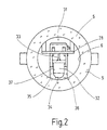
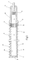
- Figures 1 and 2 show one for lighting purposes provided light source 1, to which a rod-shaped lamp 2 and a plug-in lamp socket 4 provided with a cable 3 belong.
- the lamp 2 has an outer cylindrical tube 5 made of a clearly translucent material, for example Polyacrylic or polycarbonate on a cylindrical Interior 6 limited and between two ends 7th and 8 extends.
- the front end 7 is by a glued plug 9th hermetically sealed.
- the plug 11 provides an explosion-proof cable entry It consists of an approximately cup-like Base body 14, which consists of a cylindrical side wall 15 and a floor 16 is composed.
- the educated one Plug 11 is inserted into the tube 5 such that the Bottom 16 shows outwards from the tube 5.
- the bottom 16 goes into two tubular ones cylindrical extensions 17 and 18 in one piece over the are parallel to each other.
- Each of the cylindrical extensions 17 and 18 contains an interior 19 and 21.
- the interiors 18 and 21 serve as receiving spaces for multi-lamella contact sockets 22 at one end in massive cylindrical Pins 23 go over with a tapered section 24 through corresponding holes in the bottom 16 lead, which are aligned with the interiors 19 and 21.
- the encapsulation 27 there is an elongated end at one end narrow circuit board 28 which from the plug 11 to to the stopper 9 and there in a corresponding in the stopper 9 formed slot held at the end is.
- the slot is in the drawing because of the nature of the Not recognizable.
- the circuit board 28 carries electrical or electronic Components 29, which together form a ballast 31 form, the input side with the two connecting lines 25 and 26 is connected.
- the circuit board 28 serves as a strip-shaped carrier for a large number of LEDs 32.
- the LEDs 32 are side by side along a straight line Side on the printed circuit board 28 with its connecting wires 33 soldered.
- the arrangement is such that how Figure 2 in particular shows the light exit side in shape the calotte 34 directly on the inside of the interior 6 is adjacent.
- the light emitting diodes 32 are in one with their body Molded part 35, which also consists of a clearly translucent Material exists.
- the molded part 35 is an oblong cuboid Structure in which a surface, surface 36, is cylindrically curved, corresponding to the wall of the interior 6.
- a surface, surface 36 is cylindrically curved, corresponding to the wall of the interior 6.
- a plurality of basic bores 37 the shape of which the outer contour of the LEDs 32 is adapted. In every of these basic bores 37 there is a light emitting diode 32.
- the remaining free volume of the interior 6 is in the embodiment shown with glass beads 38 completely filled. If instead of the glass beads 38 a clear translucent filler is used, for example Polystyrene resin, the molded body 35 can be omitted. On the other hand, it is with a filler, for example one Gel, conveniently present.
- a filler for example one Gel, conveniently present.
- the filler is particularly needed when the Lamp 2 explosion-proof in the type of protection "pressure-resistant Encapsulation "should be carried out.
- the filler is the remaining volume in which there is ignitable could collect gas as much as reduced in the event no dangerous internal pressures can develop during ignition, that could burst the pipe 5.
- the socket 4 consists of a cup-like outer housing 41, which on the open side in a outside protruding collar 42 ends, while the opposite closed end with a threaded connector 43 for Recording a union nut 44 is provided.
- Threaded connector 43 leads a bore in a known manner through which a clamping device for strain relief Pinching the incoming bipolar cable 3 contains.
- the strain relief becomes 44 when the union nut is tightened also known to activate and clamp the coat of the cable 3.
- a plastic insert sits inside the housing 41 45.
- Plug pins 46 and 47 are embedded in the insert 45, which protrude into bores 48, which are inserted in the Condition overlap the tubular extensions 18.
- the light emitting diodes 32 used in the lamp 2 are bright light emitting diodes with high efficiency. It deals are preferably light-emitting diodes with phosphor, the is able to start from the semiconductor barrier layer e.g. ultraviolet light in the visible range too transform.
- the light emitting diodes 32 are consequently also preferably white LEDs, since the lamp 2 is suitable for lighting purposes should be.
- white light-emitting diodes can also 3 sets of light emitting diodes are used, the Colors of the sets are selected so that they are the ones you want Generate mixed color, for example white light.
- the LEDs are 32 arranged along a straight line, that of the surface line of the cylindrical tube 5 follows. This will radiation in preferably only one direction in relation to the axis of the pipe. If a largely omniazimuthal radiation can be achieved two or more rows of light emitting diodes 32 are also used the equidistant side by side in the interior 6 run. The LEDs of the individual rows are in place star-shaped in the interior 6.
- a major advantage of the arrangement shown is among other things in the fact that no separate reflector is required because each LED internally has its own Has reflector. This simplifies the structure of the Lamp 2 in total.
- FIG. 3 shows the block diagram of the lamp 2.
- the ballast 31 has two electrical connections 52, 53 with which, for example, the connecting lines 25, 26 are connected. That delivers on the output side Ballast 31 a suitable voltage with sufficient Current in the conductor tracks present on the printed circuit board 28 55 and 56 is fed. Between these two conductor tracks 55, 56, the light emitting diodes 32 are grouped as shown connected in series. The individual groups lie in parallel at the output of the ballast 31 and are from fed this in parallel.
- the output voltage of the ballast 31 is a DC voltage, the magnitude of which the voltage is adjusted, the respective group LEDs 32 required.
- the DC voltage can be temporal to be constant, pulsating or gaping. Moreover can specify the current or the electrical if necessary Performance. So that all groups on the same Ballast 31 can be included They naturally have the same number of light emitting diodes 32.
- the internal circuit structure of the ballast 31 depends mainly on what kind of tension the terminals 52 and 53 is fed. Such Circuits are known to the person skilled in the art and require them Instead of being explained.
- FIGS. 1 and 2 A lamp 2 is illustrated in FIGS. 1 and 2.
- a lamp can be executed.
- the Do not provide plug 11 with plug pins as shown, but the connecting cable 3 leads directly through a Bore 58 in the bottom 16 of the plug 11 in the contained therein Casting compound 27.
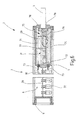
- Both the lamp 2 of Figure 1 and the lamp 4 can be combined with a protective tube 61, as shown in Figure 5.
- the protective tube 61 is cylindrical Pipe that has fins on its outer peripheral surface 62 is provided and on one side at 63 a rectangular Opening contains. Sitting in the rectangular opening a crystal clear transparent provided with individual lenses 64 Insert 65 through which the light can exit, while the rest of the protective tube 61 is opaque is.
- the protective tube 61 has an interior 66, which is dimensioned that he the lamp 2 including the union nut 51 of the jack 4 can accommodate like this 4 shows. At one end is the interior 66 closed by a wall 67, while the opposite End is open. In this area is the protective tube provided with an external thread 68 on which a tubular Screw on handle 69.
- the tubular handle 69 is approximately cup-shaped and overlaps with his Interior 71 the majority of the housing 61 of the Jack 4 and the union nut 44.
- the previous embodiments show one cylindrical lamp or luminaire using the light emitting diodes 32 together with the ballast 31 in the same room are accommodated. Accordingly, the room must be both Contains types of assemblies designed to be the highest protection standard to be fulfilled in the worst case according to the Ex regulations. For example mean that room 6 is designed as an ex- "d" room have to be.
- FIG. 6 shows an embodiment of the invention Light source 1, in which the ballast 31 in a separate chamber or housing 71 is housed that in turn in the cylindrical tube 5 of the light source 1 plugged.
- the housing 71 has the shape of a cylindrical cup with a bottom 72, in the electrical contact means 73 are inserted through the floor on both sides lead through.
- a cylindrical wall 74 integrally formed, which together with the bottom 72 a substantially cylindrical interior 75 limited.
- the cylindrical interior 75 is outward from one disc-shaped cover 76 closed on the free edge of the wall 74 is attached.
- circuit board 77 In the hermetically sealed room there is a circuit board 77 on which the electrical and electronic Components 29 of the ballast 31 soldered are.
- the power supply to the ballast 31 occurs with the help of the cable 3, which through a bore 78 in the Lid 76 is inserted.
- the cable 3 is in the cover 76 after the type of protection Ex "d" introduced and the interior 75 is after being filled with a cast resin compound or Sand filling 79 filled.
- the outgoing lines of the praise device 31 are with the two contact or bushing pins 73rd connected, which also meets the type of protection Ex "d" are anchored in the floor 72.
- To the outside protruding ends are single-pole cables 81 soldered or welded to the electrical connection to the circuit board 28 produce, on which the LEDs 32 sit. That part of the interior 6 which is between the cover 9 and the bottom 72 of the housing 71 is limited can now in the Protection type "increased safety" or “intrinsically safe” his. Flameproof encapsulation is no longer required.
- FIG 7 shows an embodiment in which a essential square-shaped lamp housing 5 is provided is in the shape of a flat bowl with one Rectangular bottom 83, in one piece with a circumferential Edge 84 is formed.
- the flat interior defined in this way becomes the edge 84 towards the light exit side overlapping cover 85 closed from a clear or matt transparent plastic material.
- the Lid 85 consists of a substantially flat plate 86, on which edge strips 87 are formed, which edge 84 reach over almost the entire length.
- the ballast 31 is housed in a compartment 87, by a separate one, for example by ultrasound or cover 88 welded on by laser is.
- Lead out of the chamber 87 as in the embodiment according to Figure 6 in flameproof encapsulated form the two Out connector pins through which the electrical connection to the conductor tracks on the printed circuit board 28 and thus the LEDs 32 is produced.
- the light source 1 does not have a permanently connected one Cable 3, but via an electrical connection or socket pins 89, the type of protection Ex "d" from the chamber 87 are brought out.
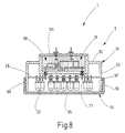
- Figure 8 finally shows an embodiment, at the housing 5 has the shape of a flat cylindrical Contains can, with a cup-shaped lower part 91 from a circular bottom 92 and one piece molded peripheral edge 93.
- a lid 94 put on like a shoe polish can, which consists of a flat, also circular floor 95 and assembles an integrally molded peripheral edge 96.
- On the inside of the edge 96 is a Cross-section sawtooth-shaped, inwardly projecting rib 97 formed, which is a rectangular cross-section rib 98 snaps over that on the outside of the side wall 93 is molded.
- bottom 92 In the bottom 92 is another cup-shaped chamber 99 trained in which the ballast 31 housed is. This further chamber 99 is circular Bottom 101 closed.
- the structure of the light source 1 corresponds 8, the structure of the embodiment of FIG 6.
- the chamber 99 is of the ignition protection type Ex "d", and the connecting pins 73 lead in a corresponding manner Through the walls of the chamber 99.
- the circuit board 28 with the LEDs 32 soldered thereon between the chamber 99 and the latched lid 94, the made of a clear or matt transparent plastic material exists, similar to the housing 5 of the cylindrical light sources 1.
- the exemplary embodiments according to FIGS. 7 and 8 contain Printed circuit boards 29, which are substantially disc-shaped are, on only one side of the circuit board 28th the LEDs 32 are arranged.
- the shape of the circuit board and the arrangement of the LEDs sitting on it 32 is adapted to the free interior space of the housing, with which the housing with regard to its outer shape also a substantially disc-shaped shape receives.
- a light source in the form of a lamp or lamp has a housing, inside of which a plurality of Light emitting diodes is arranged on a common carrier sit in the form of a circuit board. On the carrier A ballast can also be accommodated.
- the Housing is hermetically sealed to the outside and supports electrical connection means in the form of Pins or a connecting cable.
Landscapes
- Engineering & Computer Science (AREA)
- General Engineering & Computer Science (AREA)
- Power Engineering (AREA)
- Arrangement Of Elements, Cooling, Sealing, Or The Like Of Lighting Devices (AREA)
- Non-Portable Lighting Devices Or Systems Thereof (AREA)
- Fastening Of Light Sources Or Lamp Holders (AREA)
Abstract
Description
Claims (38)
- Lichtquellemit einem Gehäuse (5), das zumindest teilweise lichtdurchlässig ist und einen Innenraum (6) aufweist,mit wenigstens einer Leuchtdiode (32), die in dem Innenraum (6) des Gehäuses (5) enthalten ist und die derart ausgerichtet ist, dass von ihr ausgehendes Licht auf den lichtdurchlässigen Bereich des Gehäuses (5) gerichtet ist, undmit elektrischen Anschlussmitteln (3,23), die an dem Gehäuse (5) vorgesehen sind, um eine externe Stromquelle mit der wenigstens einen Leuchtdiode (32) elektrisch zu verbinden.
- Lichtquelle nach Anspruch 1, dadurch gekennzeichnet, dass das Gehäuse (5) stabförmig ist.
- Lichtquelle nach Anspruch 1, dadurch gekennzeichnet, dass das Gehäuse (5) zumindest im Bereich des Lichtaustritts klar lichtdurchlässig ist.
- Lichtquelle nach Anspruch 1, dadurch gekennzeichnet, dass das Gehäuse (5) lediglich im Bereich des Lichtaustritts klar lichtdurchlässig ist.
- Lichtquelle nach Anspruch 1, dadurch gekennzeichnet, dass das Gehäuse (5) eine zylindrische Außengestalt aufweist.
- Lichtquelle nach Anspruch 1, dadurch gekennzeichnet, dass das Gehäuse (5) ein Rohr ist.
- Lichtquelle nach Anspruch 1, dadurch gekennzeichnet, dass das Gehäuse (5) scheibenförmig ist.
- Lichtquelle nach Anspruch 1, dadurch gekennzeichnet, dass das Gehäuse (5) aus mineralischem Material oder aus Kunststoff besteht.
- Lichtquelle nach Anspruch 1, dadurch gekennzeichnet, dass abgesehen von Verschlussstücken (9,11) das Gehäuse (5) einstückig ist.
- Lichtquelle nach Anspruch 1, dadurch gekennzeichnet, dass das Gehäuse (5) mit einer lichtundurchlässigen Abdeckung (61) versehen ist.
- Lichtquelle nach Anspruch 11, dadurch gekennzeichnet, dass sich die Abdeckung in dem Gehäuse (5) befindet.
- Lichtquelle nach Anspruch 11, dadurch gekennzeichnet, dass das Gehäuse (5) in die Abdeckung (61) eingesetzt ist.
- Lichtquelle nach Anspruch 1, dadurch gekennzeichnet, dass das Gehäuse (5) lediglich einen Innenraum (6) aufweist, in dem die oder alle Leuchtdioden (32) enthalten sind.
- Lichtquelle nach Anspruch 1, dadurch gekennzeichnet, dass das Volumen des Innenraums (6) des Gehäuses (5) an das Volumen der Leuchtdiode (32) oder Leuchtdioden (32) angepasst ist.
- Lichtquelle nach Anspruch 1, dadurch gekennzeichnet, dass die Leuchtdiode oder zumindest einige der Leuchtdioden (32) weiß leuchtend ist/sind.
- Lichtquelle nach Anspruch 1, dadurch gekennzeichnet,' dass sie mehrere Leuchtdioden (32) aufweist, die in dem Innenraum (6) enthalten sind.
- Lichtquelle nach Anspruch 1, dadurch gekennzeichnet, dass sie ausschließlich weiß leuchtende Leuchtdioden (32) aufweist.
- Lichtquelle nach Anspruch 1, dadurch gekennzeichnet, dass sie mehrere farbig leuchtende Leuchtdioden (32) enthält.
- Lichtquelle nach Anspruch 1, dadurch gekennzeichnet, dass sie weiß leuchtende und farbig leuchtende Leuchtdioden (32) enthält.
- Lichtquelle nach Anspruch 1, dadurch gekennzeichnet, dass die Leuchtdioden (32) längs einer oder mehrere geraden Linien oder längs einer oder mehreren Schraubenlinien in dem Gehäuse (5) angeordnet sind.
- Lichtquelle nach Anspruch 1, dadurch gekennzeichnet, dass die Leuchtdioden (32) zu einer ebenen, gekrümmten oder ringförmigen Fläche angeordnet sind.
- Lichtquelle nach Anspruch 1, dadurch gekennzeichnet, dass die Leuchtdioden (32) auf einem Träger vorzugsweise in Gestalt einer Leiterplatte (28) sitzen.
- Lichtquelle nach Anspruch 1, dadurch gekennzeichnet, dass ein Formkörper (35) vorhanden ist, in dem die Leuchtdioden (32) stecken.
- Lichtquelle nach Anspruch 1, dadurch gekennzeichnet, dass der freie Innenraum (6) des Gehäuses (5) mit einem lichtdurchlässigen Mittel (38) zumindest überwiegend ausgefüllt ist.
- Lichtquelle nach Anspruch 24, dadurch gekennzeichnet, dass das lichtdurchlässige Mittel (38) ein körniges fließfähiges Mittel ist.
- Lichtquelle nach Anspruch 1, dadurch gekennzeichnet, dass in dem Gehäuse (5) elektrische und/oder elektronische Schaltmittel (29) enthalten sind.
- Lichtquelle nach Anspruch 1, dadurch gekennzeichnet, dass in dem Gehäuse (5) eine elektrische Vorschalteinrichtung (32) enthalten ist, die derart gestaltet ist, dass sie die Versorgungsspannung der Lichtquelle an die elektrischen Parameter der Leuchtdiode (32) oder Leuchtdioden (32) anpasst.
- Lichtquelle nach Anspruch 1, dadurch gekennzeichnet, dass die Leuchtdioden (32) parallel oder in Serie geschaltet sind.
- Lichtquelle nach Anspruch 1, dadurch gekennzeichnet, dass die Leuchtdioden (32) gruppenweise parallel geschaltet sind.
- Lichtquelle nach Anspruch 1, dadurch gekennzeichnet, dass die Anschlussmittel (23) Steckverbinder sind.
- Lichtquelle nach Anspruch 1, dadurch gekennzeichnet, dass die Anschlussmittel (3) von einem mehrpoligen Kabel gebildet sind.
- Lichtquelle nach Anspruch 31, dadurch gekennzeichnet, dass das Kabel (3) explosionsgeschützt in den Innenraum (6) eingeführt ist.
- Lichtquelle nach Anspruch 1, dadurch gekennzeichnet, dass sie explosionsgeschützt ausgeführt ist.
- Lichtquelle nach Anspruch 1, dadurch gekennzeichnet, dass sie in der Zündschutzart "druckfeste Kapselung" ausgeführt ist.
- Lichtquelle nach Anspruch 1, dadurch gekennzeichnet, dass sie eine Leuchte bildet.
- Lichtquelle nach Anspruch 1, dadurch gekennzeichnet, dass sie eine Lampe (2) bildet.
- Lichtquelle nach Anspruch 27, dadurch gekennzeichnet, dass für das Vorschaltgerät (31) eine Kammer (75,87,99) vorgesehen ist, die gegenüber dem Raum, der die Leuchtdioden (32) enthält abgedichtet ist.
- Lichtquelle nach Anspruch 37, dadurch gekennzeichnet, dass die Kammer (75) für das Vorschaltgerät in einem Gehäuse (71) angeordnet ist, das in das Gehäuse (5) der Lichtquelle (1) eingesetzt ist.
Applications Claiming Priority (2)
| Application Number | Priority Date | Filing Date | Title |
|---|---|---|---|
| DE10024427A DE10024427A1 (de) | 2000-05-19 | 2000-05-19 | Lichtquelle |
| DE10024427 | 2000-05-19 |
Publications (3)
| Publication Number | Publication Date |
|---|---|
| EP1156272A2 true EP1156272A2 (de) | 2001-11-21 |
| EP1156272A3 EP1156272A3 (de) | 2004-06-23 |
| EP1156272B1 EP1156272B1 (de) | 2007-12-19 |
Family
ID=7642565
Family Applications (1)
| Application Number | Title | Priority Date | Filing Date |
|---|---|---|---|
| EP01104018A Expired - Lifetime EP1156272B1 (de) | 2000-05-19 | 2001-02-20 | Lichtquelle |
Country Status (2)
| Country | Link |
|---|---|
| EP (1) | EP1156272B1 (de) |
| DE (2) | DE10024427A1 (de) |
Cited By (16)
| Publication number | Priority date | Publication date | Assignee | Title |
|---|---|---|---|---|
| EP1308670A1 (de) * | 2001-10-30 | 2003-05-07 | Centaurea Oy | Explosionsgeschützte Leuchte |
| WO2004097177A1 (de) * | 2003-05-02 | 2004-11-11 | Tiefenbach Control Systems Gmbh | Einrichtung zur beleuchtung der ausbaugestelle in einem streb |
| SG115524A1 (en) * | 2002-03-13 | 2005-10-28 | Bartec Gmbh | Indicating light |
| EP1630475A1 (de) * | 2004-08-27 | 2006-03-01 | Centaurea Oy | Aufbau einer Beleuchtungsvorrichtung |
| EP1394465A3 (de) * | 2002-08-29 | 2006-05-10 | Telectra Limited | Beleuchtungseinrichtung |
| EP1808878A1 (de) * | 2006-01-11 | 2007-07-18 | Siemens Aktiengesellschaft | Elektrische Einrichtung mit Ausschaltung des Laststromkreises in explosionsgefährdeter Umgebung |
| DE102007040272A1 (de) * | 2007-08-24 | 2009-02-26 | BöSha Technische Produkte GmbH & Co. KG | Leuchte für explosionsgefährdete Bereiche |
| EP1736703A3 (de) * | 2005-06-20 | 2009-03-18 | Cooper Crouse-Hinds GmbH | Leuchtenunterbaugruppe |
| NL1035324C2 (nl) * | 2008-04-22 | 2009-10-26 | J M Geluk Beheer B V | Explosieveilige verlichtingsinrichting. |
| DE102008020998A1 (de) * | 2008-04-25 | 2009-10-29 | BöSha Technische Produkte GmbH & Co. KG | Eigensicherer Scheinwerfer |
| WO2010057766A1 (de) * | 2008-11-19 | 2010-05-27 | M I P Center Gmbh | Leuchteinrichtung für beleuchtungszwecke und leuchte mit einer solchen leuchteinrichtung |
| NL1037176C2 (en) * | 2009-08-05 | 2011-02-08 | J M Geluk Beheer B V | Explosion proof electronic device and method of manufacturing such a device. |
| CN102762911A (zh) * | 2009-11-26 | 2012-10-31 | 欧司朗股份有限公司 | 线条灯 |
| CN104100867A (zh) * | 2014-07-22 | 2014-10-15 | 山东神舟光电科技有限公司 | Led防爆灯 |
| DE102014214603A1 (de) * | 2014-07-24 | 2016-01-28 | Osram Gmbh | Halbleiterlampe |
| WO2018219695A1 (de) * | 2017-06-01 | 2018-12-06 | R. Stahl Schaltgeräte GmbH | Explosionsgeschützte leuchte |
Families Citing this family (11)
| Publication number | Priority date | Publication date | Assignee | Title |
|---|---|---|---|---|
| DE102004044166B4 (de) * | 2004-09-13 | 2009-02-12 | BöSha GmbH + Co KG | Explosionsgeschützte Leuchte mit Leuchtdioden als Lichtquelle |
| DE102008025182A1 (de) * | 2008-05-26 | 2009-12-03 | Ingo Maurer Gmbh | Leuchtelement und Verfahren zur Herstellung eines Leuchtelements |
| DE102008029980A1 (de) * | 2008-06-24 | 2010-02-11 | Bruno Gruber | Spannungswandler mit integrierter LED |
| US8093609B2 (en) * | 2009-05-01 | 2012-01-10 | Abl Ip Holding Llc | Light emitting diode arrangement for high safety requirements |
| DE102010018784A1 (de) | 2010-04-29 | 2011-11-03 | R.Stahl Schaltgeräte GmbH | Leiterplatte mit druckfest gekapseltem Teilgehäuse |
| DE102010017460B4 (de) | 2010-06-18 | 2013-05-08 | R. Stahl Schaltgeräte GmbH | Explosionsgeschütztes Leuchtmittel |
| DE102011086628A1 (de) * | 2011-11-18 | 2013-05-23 | Tridonic Jennersdorf Gmbh | Rohrförmige LED-Lampe |
| DE102012204510A1 (de) * | 2011-11-18 | 2013-05-23 | Tridonic Jennersdorf Gmbh | Rohrförmige LED-Lampe |
| DE102012101411B4 (de) | 2012-02-22 | 2016-02-18 | R.Stahl Schaltgeräte GmbH | Explosionsgeschützte Leuchte mit eingegossener Optik |
| DE102015122510A1 (de) * | 2015-12-22 | 2017-06-22 | Rehau Ag + Co | Leuchtvorrichtung mit einer länglichen Leuchte und einem Schutzelement aus einem Kunststoffmaterial |
| DE102017126348B4 (de) | 2017-11-10 | 2019-06-19 | Ledvance Gmbh | Leuchtmittel und Verfahren zur Herstellung eines Leuchtmittels |
Family Cites Families (8)
| Publication number | Priority date | Publication date | Assignee | Title |
|---|---|---|---|---|
| DE2531968C2 (de) * | 1975-07-17 | 1986-02-13 | R. Stahl Schaltgeräte GmbH, 7118 Künzelsau | Explosionsgeschützter Leuchtmelder |
| DE3639485A1 (de) * | 1986-11-18 | 1988-05-26 | Karl Kapfer | Explosionsgeschuetztes elektrisches geraet |
| NO176415C (no) * | 1992-10-16 | 1995-03-29 | Technor As | Lyslist for nivåglass |
| BE1007825A5 (fr) * | 1993-12-15 | 1995-10-31 | Niezen Michel | Dispositif lumineux. |
| US5685631A (en) * | 1995-03-09 | 1997-11-11 | Dobert; Frank | Replacement safety light system |
| US5890794A (en) * | 1996-04-03 | 1999-04-06 | Abtahi; Homayoon | Lighting units |
| DE29900320U1 (de) * | 1999-01-04 | 1999-04-01 | Infosystems Gmbh | Bausatz für eine Beleuchtungsvorrichtung |
| US6184628B1 (en) * | 1999-11-30 | 2001-02-06 | Douglas Ruthenberg | Multicolor led lamp bulb for underwater pool lights |
-
2000
- 2000-05-19 DE DE10024427A patent/DE10024427A1/de not_active Withdrawn
-
2001
- 2001-02-20 EP EP01104018A patent/EP1156272B1/de not_active Expired - Lifetime
- 2001-02-20 DE DE50113389T patent/DE50113389D1/de not_active Expired - Lifetime
Non-Patent Citations (1)
| Title |
|---|
| None |
Cited By (26)
| Publication number | Priority date | Publication date | Assignee | Title |
|---|---|---|---|---|
| EP1308670A1 (de) * | 2001-10-30 | 2003-05-07 | Centaurea Oy | Explosionsgeschützte Leuchte |
| SG115524A1 (en) * | 2002-03-13 | 2005-10-28 | Bartec Gmbh | Indicating light |
| EP1394465A3 (de) * | 2002-08-29 | 2006-05-10 | Telectra Limited | Beleuchtungseinrichtung |
| WO2004097177A1 (de) * | 2003-05-02 | 2004-11-11 | Tiefenbach Control Systems Gmbh | Einrichtung zur beleuchtung der ausbaugestelle in einem streb |
| US7659675B2 (en) | 2003-05-02 | 2010-02-09 | Tiefenbach Control Systems Gmbh | Device for illuminating the stope support at a longwall face |
| EP1630475A1 (de) * | 2004-08-27 | 2006-03-01 | Centaurea Oy | Aufbau einer Beleuchtungsvorrichtung |
| WO2006021620A1 (en) * | 2004-08-27 | 2006-03-02 | Centaurea Oy | A construction of an illuminator |
| EP1736703A3 (de) * | 2005-06-20 | 2009-03-18 | Cooper Crouse-Hinds GmbH | Leuchtenunterbaugruppe |
| EP1808878A1 (de) * | 2006-01-11 | 2007-07-18 | Siemens Aktiengesellschaft | Elektrische Einrichtung mit Ausschaltung des Laststromkreises in explosionsgefährdeter Umgebung |
| US7679881B2 (en) | 2006-01-11 | 2010-03-16 | Siemens Aktiengesellschaft | Electrical entity with opening of the load current circuit in an explosion-vulnerable environment |
| DE102007040272A1 (de) * | 2007-08-24 | 2009-02-26 | BöSha Technische Produkte GmbH & Co. KG | Leuchte für explosionsgefährdete Bereiche |
| EP2112432A1 (de) | 2008-04-22 | 2009-10-28 | Geluk Beheer B.V. J.M. | Explosionsgeschützte Leuchte |
| NL1035324C2 (nl) * | 2008-04-22 | 2009-10-26 | J M Geluk Beheer B V | Explosieveilige verlichtingsinrichting. |
| DE102008020998A1 (de) * | 2008-04-25 | 2009-10-29 | BöSha Technische Produkte GmbH & Co. KG | Eigensicherer Scheinwerfer |
| WO2010057766A1 (de) * | 2008-11-19 | 2010-05-27 | M I P Center Gmbh | Leuchteinrichtung für beleuchtungszwecke und leuchte mit einer solchen leuchteinrichtung |
| NL1037176C2 (en) * | 2009-08-05 | 2011-02-08 | J M Geluk Beheer B V | Explosion proof electronic device and method of manufacturing such a device. |
| CN102762911B (zh) * | 2009-11-26 | 2015-03-25 | 欧司朗股份有限公司 | 线条灯 |
| CN102762911A (zh) * | 2009-11-26 | 2012-10-31 | 欧司朗股份有限公司 | 线条灯 |
| US8944630B2 (en) | 2009-11-26 | 2015-02-03 | Osram Gmbh | Linear lamp |
| CN104100867A (zh) * | 2014-07-22 | 2014-10-15 | 山东神舟光电科技有限公司 | Led防爆灯 |
| DE102014214603A1 (de) * | 2014-07-24 | 2016-01-28 | Osram Gmbh | Halbleiterlampe |
| CN105299485A (zh) * | 2014-07-24 | 2016-02-03 | 欧司朗有限公司 | 半导体灯 |
| WO2018219695A1 (de) * | 2017-06-01 | 2018-12-06 | R. Stahl Schaltgeräte GmbH | Explosionsgeschützte leuchte |
| KR20200014826A (ko) * | 2017-06-01 | 2020-02-11 | 알. 슈탈 샬트제라테 게엠베하 | 방폭 조명기구 |
| US11371689B2 (en) * | 2017-06-01 | 2022-06-28 | R. Stahl Schaltgeräte GmbH | Explosion-proof luminaire |
| KR102500893B1 (ko) | 2017-06-01 | 2023-02-20 | 알. 슈탈 샬트제라테 게엠베하 | 방폭 조명기구 |
Also Published As
| Publication number | Publication date |
|---|---|
| EP1156272A3 (de) | 2004-06-23 |
| EP1156272B1 (de) | 2007-12-19 |
| DE10024427A1 (de) | 2001-12-20 |
| DE50113389D1 (de) | 2008-01-31 |
Similar Documents
| Publication | Publication Date | Title |
|---|---|---|
| EP1156272B1 (de) | Lichtquelle | |
| DE2531968C2 (de) | Explosionsgeschützter Leuchtmelder | |
| EP2815177B1 (de) | Leuchtmodul | |
| DE3333135C2 (de) | Explosionsgeschütztes elektrisches Meldegerät | |
| EP2183794A1 (de) | Led-gehäuse | |
| DE102009056115B4 (de) | Retrofit LED-Lampe mit doppelschichtigem Kühlkörper | |
| DE102012101411A1 (de) | Explosionsgeschützte Leuchte mit eingegossener Optik | |
| EP2556286B1 (de) | Led-modul mit doppeldiffusor | |
| EP2331866A1 (de) | Lampe mit mindestens einer leuchtdiode | |
| DE202007012248U1 (de) | Leuchte | |
| EP2313683A1 (de) | Leuchtvorrichtung | |
| WO2013120958A1 (de) | Leuchtmodul-leiterplatte | |
| DE102011075161A1 (de) | Leuchtvorrichtung | |
| EP1071905B1 (de) | Signalleuchte | |
| DE202009006868U1 (de) | Rundumleuchte, vorzugsweise Rundumkennleuchte | |
| DE3406295C2 (de) | Explosionssicherer Leuchtschalter und Leuchttaster | |
| DE3430540C2 (de) | ||
| DE102007047271A1 (de) | Leuchte zur Unterwasser-Illumination | |
| EP2848859A1 (de) | Licht aussendende Einrichtung | |
| DE202007013801U1 (de) | Unterwasserleuchte mit einer Streuscheibe | |
| DE4141980A1 (de) | Leuchtdiode mit einer umhuellung | |
| EP4043781B1 (de) | Feuchtraumleuchte, insbesondere gewächshausleuchte | |
| EP1146278A2 (de) | Leuchtmittel, insbesondere für eine Signalleuchte | |
| WO2015040240A1 (de) | Lampe | |
| DE20102325U1 (de) | Leuchtmittel |
Legal Events
| Date | Code | Title | Description |
|---|---|---|---|
| PUAI | Public reference made under article 153(3) epc to a published international application that has entered the european phase |
Free format text: ORIGINAL CODE: 0009012 |
|
| AK | Designated contracting states |
Kind code of ref document: A2 Designated state(s): AT BE CH CY DE DK ES FI FR GB GR IE IT LI LU MC NL PT SE TR |
|
| AX | Request for extension of the european patent |
Free format text: AL;LT;LV;MK;RO;SI |
|
| PUAL | Search report despatched |
Free format text: ORIGINAL CODE: 0009013 |
|
| AK | Designated contracting states |
Kind code of ref document: A3 Designated state(s): AT BE CH CY DE DK ES FI FR GB GR IE IT LI LU MC NL PT SE TR |
|
| AX | Request for extension of the european patent |
Extension state: AL LT LV MK RO SI |
|
| 17P | Request for examination filed |
Effective date: 20040813 |
|
| AKX | Designation fees paid |
Designated state(s): DE FR GB IT |
|
| 17Q | First examination report despatched |
Effective date: 20050329 |
|
| RBV | Designated contracting states (corrected) |
Designated state(s): DE FR GB IT |
|
| GRAP | Despatch of communication of intention to grant a patent |
Free format text: ORIGINAL CODE: EPIDOSNIGR1 |
|
| RIC1 | Information provided on ipc code assigned before grant |
Ipc: F21Y 101/02 20060101ALN20060811BHEP Ipc: F21V 25/12 20060101AFI20060811BHEP |
|
| GRAS | Grant fee paid |
Free format text: ORIGINAL CODE: EPIDOSNIGR3 |
|
| GRAA | (expected) grant |
Free format text: ORIGINAL CODE: 0009210 |
|
| AK | Designated contracting states |
Kind code of ref document: B1 Designated state(s): DE FR GB IT |
|
| REG | Reference to a national code |
Ref country code: GB Ref legal event code: FG4D Free format text: NOT ENGLISH |
|
| GBT | Gb: translation of ep patent filed (gb section 77(6)(a)/1977) |
Effective date: 20071219 |
|
| REF | Corresponds to: |
Ref document number: 50113389 Country of ref document: DE Date of ref document: 20080131 Kind code of ref document: P |
|
| ET | Fr: translation filed | ||
| PLBI | Opposition filed |
Free format text: ORIGINAL CODE: 0009260 |
|
| PLAX | Notice of opposition and request to file observation + time limit sent |
Free format text: ORIGINAL CODE: EPIDOSNOBS2 |
|
| 26 | Opposition filed |
Opponent name: CENTAUREA OY Effective date: 20080916 |
|
| PLBB | Reply of patent proprietor to notice(s) of opposition received |
Free format text: ORIGINAL CODE: EPIDOSNOBS3 |
|
| PLBD | Termination of opposition procedure: decision despatched |
Free format text: ORIGINAL CODE: EPIDOSNOPC1 |
|
| PLBP | Opposition withdrawn |
Free format text: ORIGINAL CODE: 0009264 |
|
| PLBM | Termination of opposition procedure: date of legal effect published |
Free format text: ORIGINAL CODE: 0009276 |
|
| STAA | Information on the status of an ep patent application or granted ep patent |
Free format text: STATUS: OPPOSITION PROCEDURE CLOSED |
|
| 27C | Opposition proceedings terminated |
Effective date: 20110123 |
|
| REG | Reference to a national code |
Ref country code: DE Ref legal event code: R082 Ref document number: 50113389 Country of ref document: DE Representative=s name: RUEGER UND KOLLEGEN, DE |
|
| REG | Reference to a national code |
Ref country code: FR Ref legal event code: CA Effective date: 20140110 |
|
| REG | Reference to a national code |
Ref country code: DE Ref legal event code: R082 Ref document number: 50113389 Country of ref document: DE Representative=s name: RUEGER | ABEL PATENT- UND RECHTSANWAELTE, DE Effective date: 20140122 Ref country code: DE Ref legal event code: R081 Ref document number: 50113389 Country of ref document: DE Owner name: R.STAHL SCHALTGERAETE GMBH, DE Free format text: FORMER OWNER: R. STAHL SCHALTGERAETE GMBH, 74653 KUENZELSAU, DE Effective date: 20140122 Ref country code: DE Ref legal event code: R082 Ref document number: 50113389 Country of ref document: DE Representative=s name: RUEGER UND KOLLEGEN, DE Effective date: 20140122 Ref country code: DE Ref legal event code: R082 Ref document number: 50113389 Country of ref document: DE Representative=s name: RUEGER, BARTHELT & ABEL, DE Effective date: 20140122 Ref country code: DE Ref legal event code: R082 Ref document number: 50113389 Country of ref document: DE Representative=s name: RUEGER ABEL PATENT- UND RECHTSANWAELTE, DE Effective date: 20140122 |
|
| PGFP | Annual fee paid to national office [announced via postgrant information from national office to epo] |
Ref country code: FR Payment date: 20140219 Year of fee payment: 14 Ref country code: IT Payment date: 20140224 Year of fee payment: 14 |
|
| PGFP | Annual fee paid to national office [announced via postgrant information from national office to epo] |
Ref country code: GB Payment date: 20140218 Year of fee payment: 14 |
|
| GBPC | Gb: european patent ceased through non-payment of renewal fee |
Effective date: 20150220 |
|
| REG | Reference to a national code |
Ref country code: FR Ref legal event code: ST Effective date: 20151030 |
|
| PG25 | Lapsed in a contracting state [announced via postgrant information from national office to epo] |
Ref country code: IT Free format text: LAPSE BECAUSE OF NON-PAYMENT OF DUE FEES Effective date: 20150220 |
|
| PG25 | Lapsed in a contracting state [announced via postgrant information from national office to epo] |
Ref country code: GB Free format text: LAPSE BECAUSE OF NON-PAYMENT OF DUE FEES Effective date: 20150220 |
|
| PG25 | Lapsed in a contracting state [announced via postgrant information from national office to epo] |
Ref country code: FR Free format text: LAPSE BECAUSE OF NON-PAYMENT OF DUE FEES Effective date: 20150302 |
|
| PGFP | Annual fee paid to national office [announced via postgrant information from national office to epo] |
Ref country code: DE Payment date: 20180226 Year of fee payment: 18 |
|
| REG | Reference to a national code |
Ref country code: DE Ref legal event code: R119 Ref document number: 50113389 Country of ref document: DE |
|
| PG25 | Lapsed in a contracting state [announced via postgrant information from national office to epo] |
Ref country code: DE Free format text: LAPSE BECAUSE OF NON-PAYMENT OF DUE FEES Effective date: 20190903 |