EP1156447B1 - Drucken in gewählter Aufzeichnungsart mit reduzierter Verstellung der Rasterzeilen - Google Patents
Drucken in gewählter Aufzeichnungsart mit reduzierter Verstellung der Rasterzeilen Download PDFInfo
- Publication number
- EP1156447B1 EP1156447B1 EP01401233A EP01401233A EP1156447B1 EP 1156447 B1 EP1156447 B1 EP 1156447B1 EP 01401233 A EP01401233 A EP 01401233A EP 01401233 A EP01401233 A EP 01401233A EP 1156447 B1 EP1156447 B1 EP 1156447B1
- Authority
- EP
- European Patent Office
- Prior art keywords
- dot
- sub
- scan
- record
- displacement
- Prior art date
- Legal status (The legal status is an assumption and is not a legal conclusion. Google has not performed a legal analysis and makes no representation as to the accuracy of the status listed.)
- Expired - Lifetime
Links
Images









Classifications
-
- B—PERFORMING OPERATIONS; TRANSPORTING
- B41—PRINTING; LINING MACHINES; TYPEWRITERS; STAMPS
- B41J—TYPEWRITERS; SELECTIVE PRINTING MECHANISMS, i.e. MECHANISMS PRINTING OTHERWISE THAN FROM A FORME; CORRECTION OF TYPOGRAPHICAL ERRORS
- B41J11/00—Devices or arrangements of selective printing mechanisms, e.g. ink-jet printers or thermal printers, for supporting or handling copy material in sheet or web form
- B41J11/36—Blanking or long feeds; Feeding to a particular line, e.g. by rotation of platen or feed roller
- B41J11/42—Controlling printing material conveyance for accurate alignment of the printing material with the printhead; Print registering
-
- B—PERFORMING OPERATIONS; TRANSPORTING
- B41—PRINTING; LINING MACHINES; TYPEWRITERS; STAMPS
- B41J—TYPEWRITERS; SELECTIVE PRINTING MECHANISMS, i.e. MECHANISMS PRINTING OTHERWISE THAN FROM A FORME; CORRECTION OF TYPOGRAPHICAL ERRORS
- B41J2/00—Typewriters or selective printing mechanisms characterised by the printing or marking process for which they are designed
- B41J2/005—Typewriters or selective printing mechanisms characterised by the printing or marking process for which they are designed characterised by bringing liquid or particles selectively into contact with a printing material
- B41J2/01—Ink jet
- B41J2/21—Ink jet for multi-colour printing
- B41J2/2132—Print quality control characterised by dot disposition, e.g. for reducing white stripes or banding
- B41J2/2135—Alignment of dots
-
- G—PHYSICS
- G06—COMPUTING OR CALCULATING; COUNTING
- G06K—GRAPHICAL DATA READING; PRESENTATION OF DATA; RECORD CARRIERS; HANDLING RECORD CARRIERS
- G06K15/00—Arrangements for producing a permanent visual presentation of the output data, e.g. computer output printers
- G06K15/02—Arrangements for producing a permanent visual presentation of the output data, e.g. computer output printers using printers
- G06K15/10—Arrangements for producing a permanent visual presentation of the output data, e.g. computer output printers using printers by matrix printers
- G06K15/102—Arrangements for producing a permanent visual presentation of the output data, e.g. computer output printers using printers by matrix printers using ink jet print heads
- G06K15/105—Multipass or interlaced printing
- G06K15/107—Mask selection
-
- B—PERFORMING OPERATIONS; TRANSPORTING
- B41—PRINTING; LINING MACHINES; TYPEWRITERS; STAMPS
- B41J—TYPEWRITERS; SELECTIVE PRINTING MECHANISMS, i.e. MECHANISMS PRINTING OTHERWISE THAN FROM A FORME; CORRECTION OF TYPOGRAPHICAL ERRORS
- B41J2202/00—Embodiments of or processes related to ink-jet or thermal heads
- B41J2202/01—Embodiments of or processes related to ink-jet heads
- B41J2202/10—Finger type piezoelectric elements
-
- B—PERFORMING OPERATIONS; TRANSPORTING
- B41—PRINTING; LINING MACHINES; TYPEWRITERS; STAMPS
- B41J—TYPEWRITERS; SELECTIVE PRINTING MECHANISMS, i.e. MECHANISMS PRINTING OTHERWISE THAN FROM A FORME; CORRECTION OF TYPOGRAPHICAL ERRORS
- B41J2202/00—Embodiments of or processes related to ink-jet or thermal heads
- B41J2202/01—Embodiments of or processes related to ink-jet heads
- B41J2202/17—Readable information on the head
Definitions
- the present invention relates to a technique of recording dots on the surface of a printing medium, so as to print an image.
- Typical examples of the dot recording apparatus that records dots while scanning a dot record head in a main scanning direction and in a sub-scanning direction include serial scan printers and drum scan printers. Parameters defining the dot recording mode in such printers include the number of nozzles used for printing with regard to one color, the nozzle pitch, and the feeding amounts of sub-scan. One printer may adopts a plurality of different dot recording modes having different settings for some of these parameters.
- Pixels which are the measure for defining the dot recording position, are virtually arranged along the width and the length of a printing medium.
- An array of pixels arranged in the main scanning direction on the printing medium is called a raster line.
- the manufacturing error of an individual dot recording apparatus may, however, cause the dots on the respective raster lines to be not recorded at equal intervals in the sub-scanning direction.
- JP10-337864A selects the dot recording mode suitable for each dot recording apparatus, which has a little variation in dot array interval in the sub-scanning direction, among a plurality of dot recording modes by taking into account the manufacturing error of the dot recording apparatus.
- the preamble of claim 1 is based on this publication.
- This prior art technique measures the distance between raster lines actually recorded in each dot recording mode and selects a desired dot recording mode based on the measurement results.
- This method records linear ruled lines on the raster lines with regard to all the possible combinations of nozzles that may record adjoining raster lines.
- the method of actually printing the ruled lines with regard to all the combinations of the nozzles and the sub-scan feeds in the respective dot recording modes is a heavy load and takes a significantly long time.
- the object of the present invention is thus to provide a technique that enables a desired dot record mode to be readily set in an individual dot recording apparatus.
- the present invention applies some technique to recording dots on a printing medium with a dot record head having a plurality of dot forming elements, which are used to form dots on the printing medium, by carrying out main scan and sub-scan, where the main scan shifts at least one of the dot record head and the printing medium in a main scanning direction and the sub-scan shifts at least one of the dot record head and the printing medium in a sub-scanning direction perpendicular to the main scanning direction.
- First displacement data is generated which substantially represents deviations of dot recording positions in the sub-scanning direction with respect to the plurality of dot forming elements from a reference dot recording position by a reference dot forming element selected among the plurality of dot forming elements.
- Second displacement data is also generated which substantially represents feeding errors of the sub-scan in the sub-scanning direction.
- a dot record mode is selected among a plurality of dot record modes, based on the first displacement data and the second displacement data, each of the dot record modes specifying operations of the main scan and the sub-scan to record dots, the plurality of dot record modes having a same dot resolution and a substantially same recording speed but different combinations of feeding amounts for the sub-scan carried out in respective intervals of adjoining passes of the main scan. Then the main scan and the sub-scan are carried out to record dots in the selected dot record mode.
- This arrangement enables a deviation of dot recording position on each raster line to be checked easily without actually recording dots on the raster line.
- the optimum dot record mode is then selected, based on the information regarding the displacement of dot recording position.
- the first displacement data is stored in the first storage unit provided on the dot record head. Even when the dot record head is replaced with a new one, this arrangement enables a desired dot record mode suitable for the new dot record head to be selected.
- One applicable dot recording method carries out the sub-scan by a predetermined combination of feeding amounts in respective intervals of adjoining sub-scan feeds, so as to record dots on each raster line on the printing medium.
- the dot record mode is selected according to the procedure discussed below.
- a sum of accumulated feeding errors of the sub-scan and a deviation of a dot recording position in the sub-scanning direction is calculated.
- the accumulated feeding errors of the sub-scan is the errors with respect to each raster line of interest efore the raster line of interest on the printing medium is recorded.
- the deviation of a dot recording position in the sub-scanning direction is the deviation by a dot forming element used for recording the raster line of interest from the reference dot recording position.
- the sum is specified as a displacement of dot recording position on each raster line.
- a evaluation value relating to a variation in intervals of adjoining raster lines in the sub-scanning direction is calculated based on the displacement of dot recording position on each raster line on the printing medium, and selecting the dot record mode according to the evaluation value.
- This arrangement enables the displacement of dot recording position to be calculated with high accuracy from the feeding errors of sub-scan and the deviation of the dot recording position with regard to the corresponding dot forming element.
- the displacement of dot recording position is calculated with regard to an equal number of raster lines in each of the dot record modes. This application ensures the accurate evaluation of the displacement and the selection of the appropriate dot record mode even when the evaluation value is affected by the number of samples.
- the displacement of dot recording position may be calculated with regard to raster lines to be recorded while one set of the sub-scan is carried out by the combination of feeding amounts for each dot record mode.
- the arrangement of calculating the displacement of dot recording position on each of the above raster lines ensures the appropriate evaluation of the displacement in each dot record mode.
- the second displacement data may be generated according to the following procedure.
- the dot record head is shifted in a direction identical with the main scanning direction and recording dots with an identical dot forming element, while carrying out the sub-scan by the combination of feeding amounts in respective intervals of adjoining shifts, so as to record a sub-scan-induced displacement detection pattern in each dot record mode.
- the sub-scan-induced displacement detection pattern is read with a sensor. Then the second displacement data is generated based on an output of the sensor.
- This application enables the feeding errors of sub-scan to be evaluated based on the actual printing result. Since the identical dot forming element is used to record dots, the net feeding errors of sub-scan can be evaluated adequately.
- the first displacement data may be generated according to the following procedure.
- Each of the dot forming elements are driven while shifting the dot record head in a direction identical with the main scanning direction, so as to print a head-induced displacement detection pattern.
- the head-induced displacement detection pattern is read with a sensor. Then the first displacement data is generated based on an output of the sensor.
- This application enables the deviations of the dot recording positions in the sub-scanning direction with regard to the respective dot forming elements to be evaluated based on the actual printing result. Since dots are recorded without any sub-scan, the net deviations of the dot recording positions intrinsic to the respective dot forming elements can be evaluated adequately.
- Fig. 1 is a block diagram illustrating the structure of an image processing system in one embodiment of the present invention.
- the image processing system includes a scanner 12, a personal computer 90, and a color printer 22.
- the personal computer 90 has a color display 21.
- the scanner 12 reads color image data from a color original and supplies original color image data ORG composed of three color components, R, G, and B, to the computer 90.
- the computer 90 includes a CPU, a RAM, and a ROM, and other constituents (none of them is shown).
- an application program 95 works under the control of a predetermined operating system.
- a video driver 91 and a printer driver 96 are incorporated in the operating system.
- the application program 95 outputs final color image data FNL via these drivers 91 and 96.
- the application program 95 which carries out series of processing like generation and retouching of images, inputs an original image read by the scanner 12, makes the input image subject to a predetermined series of processing, and causes a resulting processed image to be displayed on the color display 21 via the video driver 91.
- the printer driver 96 in the computer 90 receives image information from the application program 95 and converts the image information to signals printable by the printer 22 (in this embodiment, binarized signals with regard to the respective colors, C, M, Y, and K, used in the printer 22).
- the printer driver 96 includes a rasterizer 97 that converts color image data processed by the application program 95 to image data of a printing resolution, a color correction modules 98 that converts the image data to another image data including color components for the ink colors C, M, Y used in the printer 22, and a color correction table CT that is referred to by the color correction module 98.
- the printer driver 96 further includes a halftone module 99 that generates halftone image data, which expresses the density of the image according to the presence or absence of ink at each dot position, based on the color corrected image data.
- the printer driver 96 also includes a print mode setting module 110 that functions to write print mode selection information (discussed later) into a memory of the color printer 22.
- Fig. 2 schematically illustrates the structure of the printer 22.
- the printer 22 has a sub-scan mechanism of driving a sheet feed motor 23 to feed a sheet of printing paper P, a main scan mechanism of driving a carriage motor 24 to move a carriage 31 forward and backward along an axis of a platen 26, a head driving mechanism of driving a print head 28 mounted on the carriage 31 to implement ink ejection and dot creation, and a control circuit 40 that controls transmission of signals to and from the sheet feed motor 23, the carriage motor 24, the print head 28, and a control panel 32.
- a black ink cartridge 71 for black ink (K) and a color ink cartridge 72 in which three color inks, that is, cyan (C), magenta (M), and yellow (Y), are accommodated are detachably attached to the carriage 31 in the printer 22.
- a total of four ink ejection heads 61 through 64 are formed on the print head 28 that is disposed in the lower portion of the carriage 31.
- Ink conduits (not shown) are formed in the bottom of the carriage 31 to lead supplies of inks from ink reservoirs to the respective ink ejection heads.
- the ink conduits are fitted in connection ports formed in the respective ink cartridges, so that the supplies of the respective color inks are flown into the corresponding ink ejection heads 61 through 64.
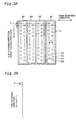
- Fig. 3A shows an arrangement of ink ejection nozzles in the respective ink ejection heads 61 through 64.
- the first ink ejection head 61 has a nozzle array for black ink.
- the second through the fourth ink ejection heads 62 through 64 respectively have nozzle arrays for cyan, magenta, and yellow inks.
- the four nozzle arrays are mounted at an identical sub-scanning position.
- Each of the four nozzle arrays includes a plurality of nozzles (dot forming elements) n arranged in zigzag at a fixed nozzle pitch k in the sub-scanning direction.
- An ink particle Ip is ejected at a high speed from each nozzle n.
- the ink particles Ip soak into the printing paper P set on the platen 26, so as to form dots as shown in Fig. 3B and implement printing.
- the plurality of nozzles n included in each nozzle array may be arranged in alignment, instead of in zigzag.
- the zigzag arrangement shown in Fig. 3A has an advantage that the nozzle array can be designed to have a small nozzle pitch k.
- the printer 22 drives the sheet feed motor 23 to rotate the platen 26 and other related rollers to thereby feed the printing paper P.
- the printer 22 also drives the carriage motor 24 to move the carriage 31 back and forth, and simultaneously actuates piezoelectric elements provided in the respective ink ejection heads 61 through 64 of the print head 28 to eject the respective inks. These procedures enable a multi-color image to be printed on the printing paper P.
- the mechanism of feeding the printing paper P has a gear train (not shown) that transmits the rotations of the sheet feed motor 23 to the platen 26 and a sheet feed roller (not shown).
- the mechanism of reciprocating the carriage 31 includes a sliding shaft 34 that is arranged in parallel with the axis of the platen 26 to support the carriage 31 in a slidable manner, a pulley 38 that is combined with the carriage motor 24 to support an endless drive belt 36 spanned therebetween, and a position sensor 39 that detects the carriage 31 at its reference position.
- the control circuit 40 includes a programmable ROM (PROM) 42 as a rewritable non-volatile memory as shown in Fig. 2 , in addition to a CPU and main memories like a ROM and a RAM (not shown).
- PROM 42 stores dot record mode information including parameters with regard to a plurality of dot record modes.
- the "dot record mode” represents a dot recording mode defined by the number of working nozzles N in each nozzle array actually used for printing and the sub-scan feed amount L.
- the term “recording process” is substantially synonymous with the terms “record mode” and "printing mode”. Concrete examples of the dot record mode and their parameters will be discussed later.
- PROM 42 also stores print mode selection information, which is used to select a desired dot record mode among the plurality of dot record modes.
- print mode selection information is 4-bit data.
- the dot record mode information is read from the PROM 42 by the printer driver 96 (see Fig. 1 ), when the printer driver 96 is installed on the start of the computer 90.
- the printer driver 96 reads the dot record mode information corresponding to a desired dot record mode specified by the print mode selection information from the PROM 42.
- the series of processing by the rasterizer 97 and the halftone module 99 and the main scan and sub-scan operations are carried out according to the input dot record mode information.
- PROM 42 may be any rewritable non-volatile memory, and a diversity of non-volatile memories like an EEPROM and a flash memory may be applicable for the PROM 42. While it is preferable that the print mode selection information is stored in the rewritable non-volatile memory, the dot record mode information may be stored in a non-rewritable ROM. The dot record mode information may be stored in a storage unit other than the PROM 42 or may alternatively be registered in the printer driver 96.
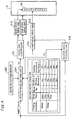
- Fig. 4 is a functional block diagram showing the structure relating to drive control operations according to the dot record mode.
- the functional block diagram includes a mode selection memory 220, a record mode setting unit 204, a record mode table 206, a drive unit controller 208, a main scan drive unit 210, a sub-scan drive unit 212, a print head drive unit 214, a raster data storage unit 216, the print head 28, and the printing paper P.
- the mode selection memory 220 and the record mode table 206 respectively correspond to the third storage unit and the record mode storage unit of the present invention.
- the mode selection memory 220 stores the print mode selection information that is used to specify a desired dot record mode.
- the record mode table 206 stores the dot record mode information representing a plurality of dot record modes.
- the dot record mode information includes a printing resolution, a mode class, a record mode number allocated to each record mode, the number of working nozzles N, and the sub-scan feed amount L.
- the printing resolution represents the resolution of dots recorded on the printing paper P.
- the mode class specifies one of the two classes "Fast" and "Fine".
- the "Fine" mode class is an overlap record mode that causes each raster line to be recorded with a plurality of nozzles.
- the "Fast" mode class is not an overlap record mode and is the mode that causes each raster line to be recorded with each nozzle by one pass of the main scan.
- three dot record modes are registered for the "720 dpi, Fine" mode. Record mode numbers 1, 2, and 3 are allocated to these dot record modes.
- the number of working nozzles N represents the number of nozzles actually used for printing.
- the sub-scan feed amount L represents the number of dot spaces by which the printing paper P is fed in the course of sub-scan.
- the dot record mode information also includes a variety of other parameters for specifying the main scan and sub-scan operations, although such parameters are omitted from the illustration of Fig. 4 .
- the record mode setting unit 204 sends parameters, which specify the main scan and sub-scan operations, to the drive unit controller 208 and the raster data storage unit 216 according to the print data transmitted from the computer 90 and the print mode selection information transmitted from the mode selection memory 220 in the PROM 42.
- the print data here is the same as the final color image data FNL shown in Fig. 1 .
- a header portion (not shown) of the print data includes data representing the printing resolution and the mode class.
- the record mode setting unit 204 specifies the dot record mode used for printing, based on the printing resolution, the mode class, and the print mode selection information transmitted from the mode selection memory 220.
- the plural dot record modes as possible options are registered only for the "720 dpi, Fine" mode in the example of Fig. 4 .
- one dot record mode is specified only based on the printing resolution and the mode class regardless of the print mode selection information,.
- the record mode setting unit 204 transmits the scanning parameters, which include the number of working nozzles N and the sub-scan feed amount L, with regard to the dot record mode thus specified to the drive unit controller 208 and the raster data storage unit 216. As discussed later, the number of working nozzles N and the sub-scan feed amount L may be varied on each pass of the scan. The scanning parameters including the number of working nozzles N and the sub-scan feed amount L are thus transmitted to the drive unit controller 208 and the raster data storage unit 216, prior to each pass of the main scan.
- the raster data storage unit 216 stores the print data into a non-illustrated buffer memory according to the scanning parameters including the number of working nozzles N and the sub-scan feed amount L.
- the drive unit controller 208 controls the main scan drive unit 210, the sub-scan drive unit 212, and the print head drive unit 214 according to these scanning parameters including the number of working nozzles N and the sub-scan feed amount L.
- the record mode table 206 and the mode selection memory 220 are provided in the PROM 42.
- the record mode setting unit 204, the drive unit controller 208, and the raster data storage unit 216 are provided in the control circuit 40 shown in Fig. 2 .
- the main scan drive unit 210 is actualized by the feeding mechanism of the carriage 31 including the carriage motor 24 shown in Fig. 2 .
- the sub-scan drive unit 212 is actualized by the feeding mechanism of the printing paper P including the sheet feed motor 23.
- the print head drive unit 214 is actualized by a circuit including piezoelectric elements allocated to the respective nozzles.
- Fig. 5 shows a first dot recording mode at the dot pitch k equal to 4 dots.
- the number of sub scan feeds s denotes the number of main scan passes performed to complete dot formation on each raster line.
- the number of effective nozzles Neff is obtained by dividing the number of working nozzles N by the numbers of scan repeats s .
- nozzle numbers #0 through #7 are sequentially allocated to the eight working nozzles.
- one cycle includes four sub-scan feeds that respectively have the sub-scan feed amount L of 10, 7, 6, and 9 dots. Namely a plurality of different values are set to the sub-scan feed amount L in one cycle of sub-scan feeds.
- the positions of the eight working nozzles after the respective sub-scan feeds are shown by four different symbols.
- the right side drawing of Fig. 5 shows the dots on respective raster lines in an effective recording area recorded with the nozzles after the respective sub-scan feeds.
- the effective recording area denotes an area in which all raster lines can be recorded without any line skip.
- non-effective recording area an areas in which some raster line cannot recorded is referred to as "non-effective recording area.”
- the effective recording area starts at the 21 st raster line from the upper end of a nozzle scanning area (that is, the total area including both the effective recording area and the non-effective recording area).
- the position of the nozzles in the first pass of main scan is set at a predetermined distance from the upper end of the printing paper. The earlier and upper starting of the effective recording area thus enables recording of dots to begin at the position closer to the upper end of the printing paper.
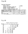
- the table of Fig. 6A shows the sub-scan feed amount L, the summation thereof ⁇ L, and the offset F of the nozzles after each pass of sub-scan.
- the left end column in the table of Fig. 6B shows the nozzles numbers #0 through #7.
- the numbers in the other columns represent which raster lines in the effective recording area are recorded with these nozzles #0 through #7 after the 0 th pass to the 7 th pass of sub-scan.
- the nozzles #5 through #7 respectively record the 1 st , 5 th , and 9 th effective raster lines.
- the nozzles #3 through #7 respectively record the 3 rd , 7 th , 11 th , 15 th , and 19 th effective raster lines.
- the effective raster lines represent raster lines in the effective recording area.
- the nozzles are arranged at the intervals of the nozzle pitch k, so that the 32 raster lines recorded in one cycle are not consecutive as clearly understood from Fig. 5 .
- the table of Fig. 6B shows which nozzles are used to record the first 32 raster lines in the effective recording area.
- the effective raster line numbers expressed by the bracketed numerals show that raster lines at the equivalent positions to those of the bracketed raster lines under the current scanning conditions have been recorded in a previous cycle.
- the value obtained by subtracting 32 from the bracketed numeral represents the effective raster line number allocated to the equivalent raster line.
- the effective raster line No. 36 recorded with the nozzle #0 is the raster line at the equivalent position to that of the effective raster line No. 4 under the current scanning conditions.
- the numerals 1 through 31 in the left end column of Fig. 7 represent the effective raster line numbers.
- the right side columns show the effective raster lines recorded with the 8 working nozzles #0 through #7 in the main scan after the respective sub-scan feeds. For example, in the main scan after 0 th pass of sub-scan, the nozzles #5 through #7 respectively record the 1 st , 5 th , and 9 th effective raster lines.
- the comparison between Fig. 7 and Fig. 6B clearly shows the relationship between the effective raster line number and the nozzle number.
- the presence or the absence of the record of the adjoining raster lines before and after each raster line of interest affects the picture quality of the raster line of interest that is currently recorded.
- the picture quality is affected by the drying degree of ink on the adjoining recorded raster lines and by the errors of sub-scan feed.
- the appearance of the pattern @ defined by the above four symbols at a relatively large period on the printing paper may deteriorate the picture quality of the resulting printed image.
- the pattern @ defined by the four symbols does not show any clear periodicity. It is accordingly expected that the resulting recorded image is not subject to significant deterioration of the picture quality due to the periodic pattern but has relatively good picture quality.
- the value ⁇ in the third left column of Fig. 7 shows the maximum number of sub-scan feeds between recording of an adjoining raster line and recording of each raster line of interest.
- This value ⁇ is hereinafter called "the differential number of sub-scans.”
- the 2 nd effective raster line is recorded with the nozzle #1 after the 2 nd pass of sub-scan
- the 1 st effective raster line is recorded with the nozzle #5 after the 0 th pass of sub-scan.
- the differential number of sub-scan feeds ⁇ thus ranges from 0 to k.
- the actual sub-scan feed amount is an exact integral multiples of the dot pitch. In the actual state, however, there are some feeding errors.
- the errors of sub-scan feed are accumulated on each pass of sub-scan. In the case where many sub-scan feeds are interposed between two passes of main scan for recording two adjoining raster lines, there may be a displacement of raster lines due to the accumulated errors of sub-scan feed between the two adjoining raster lines.
- the differential number of sub-scan feeds ⁇ shown in Fig. 7 represents the number of sub-scan feeds between recording of an adjoining raster line and recording of each raster line of interest.
- the smaller differential number of sub-scan feeds ⁇ is preferable to reduce the displacement of adjoining raster lines due to the accumulated errors of sub-scan feed.
- the sub-scan feed amount L varies as 10, 7 6, and 9 dot spaces in this order.
- the sub-scan feed amount L varies as 7, 6, 9, and 10 dot spaces in this order.
- the nozzle pitch k and the number of working nozzles N are integers that are not less than 2 and are not prime to each other.
- a plurality of different values are set to the sub-scan feed amount L.
- there are a plurality of equivalent dot recording modes having different sequences of the variation in sub-scan feed amount L but identical resolution and recording speed which of the equivalent dot recording modes attains the highest picture quality depends upon the individual printers.
- the picture quality of the image recorded by each printer is affected by the combination of errors caused by the manufacture of the printer (for example, the errors of the nozzle pitch and the errors of sub-scan feed) with the adopted scanning method in the dot recording mode (mainly the set of feeding amounts of sub-scan).
- the dot recording mode mainly the set of feeding amounts of sub-scan.
- Fig. 10 is a flowchart showing a procedure of manufacturing the printing apparatus.
- the procedure first manufactures the print head 28 at step S1 and a scan drive unit at step S2.
- the scan drive unit is a part of the color printer 22 including the main scan drive unit 210 and the sub-scan drive unit 212.
- the main scan drive unit 210 is actualized by the feeding mechanism of the carriage 31 including the carriage motor 24, and the sub-scan drive unit 212 is actualized by the feeding mechanism of the printing paper P including the sheet feed motor 23 (see Fig. 2 ).
- the procedure of step S1 generates first displacement data in the course of manufacturing the print head 28.
- the first displacement data substantially represents deviations of the dot recording positions in the sub-scanning direction by the other nozzles from the dot recording position by a reference nozzle #7 (hereinafter may be referred to as the vertical displacement).
- the procedure of step S2 generates second displacement data, which substantially represents errors of sub-scan feed in the sub-scanning direction, in the course of manufacturing the scan drive unit. The processes of generating the first and second displacement data will be discussed in detail later.
- the procedure attaches the print head 28 to the scan drive unit at step S3, and calculates a displacement of dot recording position on each raster line in each dot record mode at step S4.
- the procedure then calculates an evaluation value of each dot record mode from the calculated displacement on the raster line at step S5, and selects the optimum dot record mode based on the calculated evaluation value at step S6.
- the procedure subsequently stores the selected dot record mode into the mode selection memory 220 included in the PROM 42 (see Figs. 2 and 4 ) at step S7.
- the "720 dpi, Fine" mode has a plurality of dot record modes as selectable options.
- the procedures of steps S4 through S7 are repeatedly executed to select one optimum dot record mode with regard to each mode class.
- the information representing the selected dot record modes is collectively stored as the print mode selection information in the mode selection memory 220. The procedures of the respective steps are discussed in detail below.
- Fig. 11 is a flowchart showing the details of the process of generating the first displacement data at step S1 in the flowchart of Fig. 10 .
- the procedure of step S1 attaches the manufactured print head 28 to a predetermined test scan drive unit (not shown).
- a head-induced displacement detection pattern recording unit 324 (see Fig. 12 ) first causes the print head 28 to eject ink droplets while being fed in the direction of the main scan, so as to print ruled lines in the feeding direction at step S11.
- the ruled lines recorded here form a head-induced displacement detection pattern.
- Fig. 12 shows an example of the head-induced displacement detection pattern recorded at step S11 and a process of reading the head-induced displacement detection pattern.
- the print head 28 attached to the scan drive unit included in the printing apparatus is fed in the direction perpendicular to the alignment of the nozzle array (see Fig. 3 ) in the respective passes of main scan.
- the print head 28 is fed in the direction identical with the main scanning direction, that is, the direction perpendicular to the alignment of the nozzle array, in the process of recording the head-induced displacement detection pattern.
- the head-induced displacement detection pattern recording unit 324 which controls the print head 28 to record the ruled lines, is actualized by execution of a predetermined computer program by a computer 390, which is part of the equipment for manufacturing printers.
- Fig. 12 shows an example of horizontal ruled lines recorded with all the nozzles included in one nozzle array for one color ink.
- the numeral with the symbol # above each ruled line represents the nozzle used to record the ruled line.
- the nozzle array includes 8 nozzles #0 through #7.
- the nozzles of even ordinal numbers record ruled lines on the left half of the printing paper, whereas the nozzles of odd ordinal numbers record ruled lines on the right half of the printing paper. If the ruled lines are recorded with adjoining nozzles in an identical horizontal range on the printing paper, the adjoining ruled lines are close to each other and are not readily distinguishable from each other.
- the horizontal range in which the respective ruled lines are recorded may be divided into three sections, instead of the two sections.
- the ruled line on the lower most end (the ruled line recorded with the nozzle #7) is a common ruled line CR.
- the common ruled line CR is used as the reference line for evaluation of the displacement of the other ruled lines.
- the nozzle recording this common ruled line CR is the reference nozzle.
- the first displacement data generation unit 322 is actualized by execution of a predetermined computer program by the computer 390.
- the procedure actuates the image sensor 320 (see Fig. 12 ) to read the center positions of the respective ruled lines at step S12.
- a linear image sensor of CCDs or a two-dimensional image sensor may be applied for the image sensor 320.
- the first displacement data generation unit 322 causes each ruled line read by the image sensor 320 to be subjected to the core line process to determine the center position of the ruled line.
- the center position of each ruled line is measured as a distance DIS from the common ruled line CR.
- the center positions of the ruled lines recorded with the nozzles #0 and #1 are respectively obtained as distances DIS 0-7 and DIS 1-7 from the common ruled line CR.
- the first displacement data generation unit 322 calculates deviations of the center positions DH on the respective ruled lines recorded with the corresponding nozzles.
- Each of center position deviations DH 0 to DH 6 on the respective ruled lines represents the difference between the center position DIS measured by the image sensor 320 and a designed center position.
- the interval between the nozzles #6 and #7 is equal to the nozzle pitch k [dots] on the design.
- the designed center position on the ruled line recorded with the nozzle #6 is thus equal to k [dots], whereas the observed center position is DIS 6-7 .
- the center position deviation DH 5 with regard to the nozzle #5 is the difference between the observed center position DIS 5-7 and 2 ⁇ k [dots].
- the center position deviation DH 4 with regard to the nozzle #4 is the difference between the observed center position DIS 4-7 and 3 ⁇ k [dots].
- the center position deviations with regard to the other nozzles are defined in the same manner.
- Each of the center position deviations DH 0 to DH 6 has a positive value when the ruled line is farther from the common ruled line CR than the designed value, while having a negative value when the ruled line is closer to the common ruled lines CR than the designed value.
- the nozzle #7 is the reference nozzle, so that the center position deviation is not defined with regard to the nozzle #7.
- the center position deviations DH 0 to DH 6 are regarded as the deviations of dot recording position intrinsic to the respective nozzles #0 through #6.
- the first displacement data generation unit 322 stores the center position deviations DH 0 to DH 6 intrinsic to the respective nozzles #0 through #6 as the first displacement data into a head ID memory 202, which is provided on the print head 28.
- the head ID memory 202 corresponds to the first storage unit of the present invention.
- Fig. 13 is a flowchart showing the details of the process of generating the second displacement data at step S2 in the flowchart of Fig. 10 .
- the procedure of step S2 attaches a predetermined test head 426 (see Fig. 14 ) to the manufactured scan drive unit.
- the test head 426 has only one nozzle, from which ink is ejected.
- a sub-scan-induced displacement detection pattern recording unit 424 causes a sub-scan-induced displacement detection pattern to be printed on a sheet of printing paper set on the scan drive unit at step S21.
- the sub-scan-induced displacement detection pattern recording unit 424 causes the scan drive unit to carry out the main scan and the sub-scan in each dot record mode, while causing one nozzle on the test head 426 to eject ink and print ruled lines (the sub-scan-induced displacement detection pattern).
- the sub-scan-induced displacement detection pattern recording unit 424 is actualized by execution of a predetermined computer program by a computer 490 (see Fig. 14 ), which is part of the equipment for manufacturing printers.
- Fig. 14 shows an example of the sub-scan-induced displacement detection pattern recorded at step S21 and a process of reading the sub-scan-induced displacement detection pattern.
- the sub-scan-induced displacement detection pattern including 5 ruled lines is recorded by the combined functions of the test head 426 and the sub-scan-induced displacement detection pattern recording unit 424.
- the sub-scan-induced displacement detection pattern recording unit 424 carries out the sub-scan by one cycle of the feeding amounts of sub-scan set in each dot record mode, while printing the sub-scan-induced displacement detection pattern in the main scan. In the first dot recording mode shown in Fig.
- the ruled lines are printed in the main scan, while the sub-scan is carried out between each adjoining passes of the main scan with a variation in feeding amount as 10 dots, 7 dots, 6 dots, and 9 dots.
- This ruled line recorded prior to the sub-scan is hereinafter referred to as a reference ruled line CR2.
- These five ruled lines form the sub-scan-induced displacement detection pattern.
- the lower portion of Fig. 14 shows a linear image sensor 420 and a second displacement data generation unit 422, which are also used for the series of processing in the flowchart of Fig. 13 .
- the second displacement data generation unit 422 is actualized by execution of a predetermined computer program by the computer 490, which is part of the equipment for manufacturing printers.
- a linear image sensor of CCDs or a two-dimensional image sensor may be applied for the image sensor 420.
- the procedure actuates the image sensor 420 to read the center positions of the respective ruled lines at step S22 in the flowchart of Fig. 13 .
- the procedure of reading the center positions of the respective ruled lines at step S22 is identical with the procedure of step S12 in the flowchart of Fig. 11 .
- each ruled line is observed as a distance DRD from the reference ruled line CR2 printed prior to the sub-scan.
- the center positions of the respective ruled lines are sequentially obtained as DRD 1 to DRD 4 .
- the second displacement data generation unit 422 calculates inter-ruled line distances DSD from the observed center positions DRD of the respective ruled lines (that is, the distances from the reference ruled lines CR2) and deviations DSS of the inter-ruled line distances.
- the inter-ruled line distance represents the distance between two adjoining ruled lines among the ruled lines printed at step S21.
- the procedure of step S21 carries out the sub-scan by a predetermined feeding amount or distance between recording of one ruled line and recording of a next ruled line.
- the inter-ruled line distance DSD accordingly corresponds to each feeding distance of sub-scan between the adjoining ruled lines.
- an inter-ruled line distance DSD 10 between the reference ruled line CR2 and the second ruled line is obtained by the equation given below.
- the feeding amount of sub-scan is equal to 10 [dots] between printing of the reference ruled line CR2 and printing of the second ruled line, so that the inter-ruled line distance between the reference ruled line CR2 and the second ruled line is expressed as DSD 10 .
- DSD 10 DRD 1
- DSD 6 DRD 3 - DRD 2
- DSD 9 DRD 4 - DRD 3
- Deviations DSS 10 , DSS 7 , DSS 6 , and DSS 9 of the inter-ruled line distances respectively represent the differences between the inter-ruled line distances DSD 10 , DSD 7 , DSD 6 , and DSD 9 , which are calculated from the center positions DRD 1 through DRD 4 of the respective ruled lines measured by the image sensor 420, and designed feeding amounts of sub-scan.
- the sub-scan feed of 10 dots is carried out between printing of the reference ruled line CR2 and printing of the second ruled line, so that the designed inter-ruled line distance is equal to 10 [dots].
- the deviation DSS 10 of the inter-ruled line distance under the sub-scan feed of 10 dots is difference between the calculated inter-ruled line distance DSD 10 and the designed feeding amount 10 [dots].
- DSS 7 DSD 7 - 7 ⁇ w
- DSS 6 DSD 6 - 6 ⁇ w
- DSS 9 DSD 9 - 9 ⁇ w
- the deviations DSS 10 , DSS 7 , DSS 6 , and DSS 9 of the inter-ruled line distances respectively correspond to the errors of sub-scan feed by the feeding amounts of 10 dots, 7 dots, 6 dots, and 9 dots.
- Each of the deviations DSS 10 , DSS 7 , DSS 6 , and DSS 9 of the inter-ruled line distances has a positive value when the actual feeding amount of sub-scan is greater than the designed feeding amount, while having a negative value when the actual feeding amount of sub-scan is smaller than the designed feeding amount.
- the second displacement data generation unit 422 calculates the inter-ruled line distances DSD from the observed center positions DRD of the respective ruled lines (that is, the distances from the reference ruled line CR2) and subsequently determines the errors of sub-scan feed DSS.
- the second displacement data generation unit 422 subsequently stores the calculated errors of sub-scan feed DSS 10 , DSS 7 , DSS 6 , and DSS 9 as the second displacement data in a sub-scan displacement memory 222 included in the PROM 42 at step S24.
- the sub-scan displacement memory 222 corresponds to the second storage unit of the present invention.
- the print head 28 with the first displacement data stored in the head ID memory 202 is attached to the scan drive unit with the second displacement data stored in the sub-scan displacement memory 222.
- the dot record mode unequivocally determines how each raster line is recorded on the printing paper, that is, which nozzle is used to record the raster line and what settings of the sub-scan feed are applied prior to recording the raster line.
- the nozzle used and the settings of the sub-scan feed to record each raster line on the printing paper are varied according to the selected dot record mode. For example, in the first dot recording mode shown in Figs. 6 and 7 , the 10 th raster line is recorded with the nozzle #3 after two sub-scan feeds by the feeding amounts of 10 dots and 7 dots. In the second dot recording mode shown in Figs.
- the 10 th raster line is recorded with the nozzle #7 prior to any pass of the sub-scan.
- the displacement of dot recording position in the sub-scanning direction on each raster line is the sum of the accumulated errors of sub-scan feed and the deviation of the dot recording position intrinsic to each nozzle (the vertical displacement).
- the displacements of dot recording position on the respective raster lines are thus calculated from the first displacement data (that is, the deviations of dot recording position intrinsic to the respective nozzles) DH 0 through DH 6 and the second displacement data (that is, the errors of sub-scan feed) DSS 10 , DSS 7 , DSS 6 , and DSS 9 .
- the 10 th raster line is recorded with the nozzle #3 after the first pass of sub-scan by 10 dots and the second pass of sub-scan by 7 dots.
- the displacement of dot recording position D 1,10 on the 10 th raster line in the first recording process is expressed by the equation given below.
- the errors of the respective sub-scan feeds in the second dot recording mode are expressed as DSS 1,10 , DSS 1,7 , DSS 1,6 and DSS 1,9 .
- D 1 , 10 DSS 1 , 10 + DSS 1 , 7 - DH 3
- the 20 th raster line is recorded with the nozzle #4 after the first pass of sub-scan by 10 dots, the second pass of sub-scan by 7 dots, and the third pass of sub-scan by 6 dots.
- the first term on the right side ⁇ 1,p represents the summation of the errors of the respective sub-scan feeds DSS in the first dot record mode before the p- th raster line is recorded.
- the second term on the right side DH r represents the deviation of the dot recording position by the r- th nozzle, which records the p- th raster line, from the dot recording position by the reference nozzle.
- the dot recording position may be shifted downstream or upstream in the sub-scanning direction.
- the displacement of dot recording position D 1,p has a positive value in the downstream shift, while having a negative value in the upstream shift.
- DH r has a positive value when the position of the ruled line recorded with each nozzle is deviated relative to the position of the common ruled line CR recorded with the reference nozzle #7 toward the nozzle #1 (that is, to the upstream side in the sub-scanning direction).
- the negative sign is accordingly given to the second term on the right side DH r .
- the displacement of dot recording position D i,p on the p- th raster line thus obtained represents the difference from a designed dot recording position relative to the raster line recorded with the reference nozzle #7 prior to any pass of the sub-scan.
- the 9 th raster line shown in Fig. 7 is recorded with the reference nozzle #7 prior to any pass of the sub-scan, so that the displacement of dot recording position D 1,9 on the 9 th raster line is equal to zero.
- the first term on the right side ⁇ i,p represents the summation of the errors of the respective sub-scan feeds DSS in the i- th dot record mode before the p- th raster line is recorded.
- the second term on the right side DH r represents the deviation of the dot recording position by the r- th nozzle, which records the p- th raster line, from the dot recording position by the reference nozzle.
- Fig. 15 shows the relations among a displacement calculation unit 502 included in a computer 590, which is part of the equipment for manufacturing printers, the head ID memory 202 on the print head 28, and the sub-scan displacement memory 222 included in the scan drive unit.
- the print head 28 is incorporated in the printer 22, the print head 28 is separate from the printer 22 in the illustration of Fig. 15 for convenience. Referring back to the flowchart of Fig.
- the displacement calculation unit 502 included in a mode specification unit 522 calculates the displacement of dot recording position D i,p on each raster line according to the above procedures, based on the first displacement data DH i,p stored in the head ID memory 202 and the second displacement data DSS stored in the sub-scan displacement memory 222.
- the displacement of dot recording position D i,p on each raster line is calculated with regard to each of the dot record modes provided as selectable options.
- the mode specification unit 522 corresponds to the selection unit of the present invention.
- the mode specification unit 522 determines a difference in dot array interval ID i(p+1)-p between adjoining raster lines in each dot record mode and calculates a variance DDi of the difference in dot array interval ID i(p+1).p .
- the variance DDi of the difference in dot array interval ID i(p+1)-p represents the evaluation value in each dot record mode.
- Equation (3) when the interval between the dot array on the p- th raster line and the dot array on the (p+1)- th raster line is greater than a designed value, the difference in dot array interval ID i,(p+1)-p has a positive value. When the interval is less than the designed value, on the other hand, the difference ID i,(p+1)-p has a negative value.
- ID i , p + 1 - p D i , p + 1 - D i , p
- the mode specification unit 522 selects the dot record mode having the smallest evaluation value DDi at step S6 in the flowchart of Fig. 10 .
- the procedure selects the dot record mode having the smallest variance DDi of the difference in dot array interval ID i,(p+1)-p .
- the dot array interval between adjoining raster lines is not constant in the sub-scanning direction but is varied to be greater and less than the designed value, streaks or stripes extending in the main scanning direction may appear in the resulting printed image. Such phenomenon is called "banding".
- the difference in dot array interval ID i,(p+1)-p between adjoining raster lines in each dot record mode may have a positive value or a negative value corresponding to the greater dot array interval or the smaller dot array interval than the designed value.
- each dot record mode is evaluated by the arithmetic mean of the difference in dot array interval ID i,(p+1)-p , it is practically impossible to distinguish the dot record mode actually having a small variation in dot array interval from the dot record mode having similar rates of the greater dot array interval and the smaller dot array interval than the designed value, which cancel each other. Selection of the latter dot record mode may cause banding in the resulting printed image.
- the method of evaluating each dot record mode by the variance DDi of the difference in dot array interval ID i,(p+1)-p between adjoining raster lines does not cause such problems but enables selection of the desired dot record mode that ensures the good picture quality of the printing results.
- the mode specification unit 522 stores the number allocated to the selected dot record mode into the mode selection memory 220 included in the PROM 42 at step S7.
- the mode specification unit 522 and the displacement calculation unit 502 are actualized by execution of predetermined computer programs by the computer 590, which is part of the equipment for manufacturing printers.
- the record mode setting unit 204 in the printer 22 receives information representing the printing resolution and the mode class from the header of print data.
- the record mode setting unit 204 reads the print mode selection information corresponding to the printing resolution and the mode class from the mode selection memory 220 in the PROM 42, and subsequently reads the dot record mode information corresponding to the print mode selection information from the record mode table 206.
- the record mode setting unit 204 then gives the parameters defining the main scan and sub-scan operations to the drive unit controller 208 and the raster data storage unit 216.
- the drive unit controller 208 controls the main scan drive unit 210, the sub-scan drive unit 212, and the print head drive unit 214 to carry out an actual printing operation.
- the procedure of the above embodiment determines the displacement of dot recording position D i,p on each raster line in each dot record mode, calculates the difference in dot array interval ID i,(p+1)-p between adjoining raster lines, and selects the dot record mode having the smallest variance DDi of the difference in dot array interval ID i,(p+1)-p .
- the desired dot record mode may, however, be selected according to other criterion.
- the following describes another procedure that calculates the dot array interval between adjoining raster lines from the measured dot recording positions and the feeding amounts of sub-scan and evaluates each dot record mode based on the variance of the calculated dot array interval.
- Fig. 16 is a flowchart showing another procedure of manufacturing the printing apparatus.
- the procedure of Fig. 16 is similar to the procedure shown in the flowchart of Fig. 10 , except that the processes of steps S1a, S2a, S4a, S5a, and S6a are different from those of steps S1, S2, S4, S5, and S6 in Fig. 10 .
- Fig. 17 is a flowchart showing the details of the process of generating the first displacement data at step S1a in the flowchart of Fig. 16 .
- the procedure of Fig. 17 does not have a step corresponding to step S13 in the flowchart of Fig. 11 and includes step S14a that is different from step S14. Otherwise the process of Fig. 17 is similar to the process of Fig. 11 .
- the procedure of Fig. 17 that generates the first displacement data after the center positions DIS 0-7 to DIS 6-7 of the respective ruled lines (see Fig.
- the first displacement data generation unit 322 stores the obtained center positions DIS 0-7 to DIS 6-7 of the respective ruled lines as the first displacement data into the head ID memory 202 at step S14a.
- the center positions DIS 0-7 to DIS 6-7 of the respective ruled lines read at step S12 include the deviations of the dot recording positions intrinsic to the respective nozzles.
- the first displacement data thus substantially represents the deviations of dot recording position in the sub-scanning direction intrinsic to the respective nozzles.
- Fig. 18 is a flowchart showing the details of the process of generating the second displacement data at step S2a in the flowchart of Fig. 16 .
- the process of Fig. 18 is similar to the process shown in the flowchart of Fig. 13 , except that steps S23a and S24a are different from steps S23 and S24 in Fig. 13 .
- steps S23a and S24a are different from steps S23 and S24 in Fig. 13 .
- the second displacement data generation unit 422 calculates the inter-ruled line distances DSD 10 , DSD 7 , DSD 6 , and DSD 9 from the obtained center positions DRD 1 to DRD 4 of the respective ruled lines at step S23a.
- the inter-ruled line distances DSD 10 , DSD 7 , DSD 6 , and DSD 9 represent the actual feeding distances of sub-scan.
- the second displacement data generation unit 422 subsequently stores the calculated inter-ruled line distances (that is, the feeding distances of sub-scan) DSD 10 , DSD 7 , DSD 6 , and DSD 9 as the second displacement data into the sub-scan displacement memory 222 at step S24a.
- DRD 1 to DRD 4 represent the center positions of the respective ruled lines actually recorded with the sub-scan feeds (that is, the distances from the reference ruled line CR2), and thus include errors of sub-scan feed.
- the inter-ruled line distances (the feeding distances of sub-scan) DSD 10 , DSD 7 , DSD 6 , and DSD 9 calculated from DRD 1 to DRD 4 also include the errors of sub-scan feed.
- the second displacement data thus substantially represents the errors of sub-scan feed.
- the displacement calculation unit 502 calculates the recording positions of the dot arrays on the respective raster lines in the sub-scanning direction in each dot record mode, based on the first displacement data DIS 0-7 to DIS 6-7 and the second displacement data DSD 10 , DSD 7 , DSD 6 , and DSD 9 .
- the first displacement data DIS 0-7 to DIS 6-7 represent the positions of the dot arrays recorded with the respective nozzles relative to the position of the dot array recorded with the reference nozzle #7.
- the second displacement data DSD 10 , DSD 7 , DSD 6 , and DSD 9 represent the feeding amounts of sub-scan.
- the first term on the right side ⁇ 1,p represents the summation of the feeding amounts of sub-scan DSD in the first dot record mode before the p- th raster line is recorded.
- the second term on the right side DIS r-N0 represents the center position of the p- th raster line recorded with the r- th nozzle relative to the center position of a reference raster line recorded with a reference nozzle #N0.
- the recording position SSR 1,p of the dot array on the p- th raster line has a positive value in the downstream direction of sub-scan feed.
- DIS r-N0 represents a distance between the ruled line recorded with each nozzle and the common ruled line CR.
- DIS r-N0 shows the observed center position of each ruled line recorded with each nozzle relative to the center position of the common ruled line CR recorded with the reference nozzle #N0 (#7 in the example of Fig. 12 ), which is located on the most downstream side in the sub-scanning direction.
- the negative sign is accordingly given to the second term on the right side DIS r-N0 .
- the first term on the right side ⁇ i,p (DSD i ) represents the summation of the feeding amounts of sub-scan DSD in the i- th dot record mode before the p- th raster line is recorded.
- the second term on the right side DIS r-N0 represents the center position of the p- th raster line recorded with the r- th nozzle relative to the center position of the reference raster line recorded with the reference nozzle #N0 in the i- th dot record mode.
- the displacement calculation unit 502 calculates the recording position SSR i,p of the dot array on each raster line in the sub-scanning direction according to Equation (4) given above.
- the procedures of steps S4a through S7 are repeatedly executed to select one optimum dot record mode with regard to each mode class as in the case of the above embodiment.
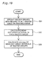
- Fig. 19 is a flowchart showing the details of the process of calculating the evaluation value with regard to each dot record mode at step S5a in the flowchart of Fig. 16 .
- Fig. 20 shows the principle of calculating the dot array interval between adjoining raster lines as the evaluation value.
- the dot array recorded on each raster line is shown as the ruled line.
- Dot arrays of ten raster lines, that is, (p-5)- th to (p+4)- th raster lines, are shown in Fig. 20 .
- the displacement calculation unit 502 calculates the evaluation value with regard to each dot record mode based on the recording positions of the dot arrays according to the procedures discussed below.
- the displacement calculation unit 502 first specifies raster groups of plural consecutive raster lines with regard to all the raster lines on the printing paper at step S31.
- each raster group may include six consecutive raster lines.
- the respective raster groups are specified by sequentially shifting the included raster lines by one.
- the displacement calculation unit 502 subsequently calculates the mean dot array interval between adjoining raster lines included in each raster group at step S32.
- the dot array interval Dras i,q-p between the p-th raster line and the q- th raster line in the i- th dot record mode is expressed by Equation (5) given below.
- Dras i , q , p SSR i , q - SSR i , p
- a j- th raster group includes (p-3)- th through (p+2)- th raster lines.
- the mean dot array interval MDras i,j in the j- th raster group is obtained by dividing the dot array interval Dras i,(p+2)-(p-3) between both the end raster lines, that is, the (p-3)- th raster line and the (p+2)- th raster line, by the number of intervals 5.
- the dot array interval Dras i,q-p is calculated according to Equation (5) given above.
- MDras i,j SSR i , p + 2 - SSR i , p - 3 / 5
- the mode specification unit 522 calculates the mean dot array interval MDras i,j in each raster group according to Equation (7) given above at step S32 in the flowchart of Fig. 19 .
- the mode specification unit 522 calculates a difference min-max(MDras i,j ) between the largest and the smallest mean dot array intervals MDras i,j of the raster groups in each dot record mode.
- the difference min-max(MDras i,j ) is specified as the evaluation value regarding the inter-ruled line distance in each dot record mode.
- the displacement calculation unit 502 calculates the evaluation value min-max(MDras i,j ) in each record mode according to the above procedures.
- the dot record mode having the smallest evaluation value min-max(MDras i,j ) is selected.
- the banding occurs due to the variation in dot array interval between adjoining raster lines relative to the designed value.
- the method adopted here calculates the mean dot array interval in each raster group and selects the dot record mode having the smallest difference between the maximum mean dot array interval and the minimum mean dot array interval, that is, the dot record mode having little variation in dot array interval among different raster groups. This arrangement enables selection of the desired dot record mode having little chance of causing the banding.
- the evaluation value may be the difference between the maximum value and the minimum value, the variance, the standard deviation, or any of other appropriate values.
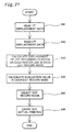
- Fig. 21 is a flowchart showing a procedure of determining the dot record mode after attachment of the print head to the scan drive unit.
- Fig. 22 is a block diagram showing the structure of a printer driver 96a that includes a mode specification unit 632 as a functional unit thereof.
- the setting of the first displacement data (see Fig. 11 ), the setting of the second displacement data (see Fig. 13 ), and the selection of the dot record mode (see Fig. 10 ) are carried out in the course of manufacturing the printer. Any of these processes may alternatively be carried out after the attachment of the print head to the scan drive unit.
- the selection of the dot record mode may be performed after the attachment of the print head to the scan drive unit according to the procedures discussed below.
- the procedure stores the first displacement data into the head ID memory 202 and the second displacement data into the sub-scan displacement memory 222 provided in the PROM 42 in the course of manufacturing the printer like the procedure of Fig. 10 .
- the mode specification unit 632 included in the printer driver 96a has the equivalent functions to those of the mode specification unit 522 shown in Fig. 15 .
- the other constituents of the printing apparatus are similar to those of the printing apparatus of the embodiment discussed above.
- the functional units in the printer driver 96a that are the same as the functional units in the printer driver 96 shown in Fig. 1 are omitted from the illustration of Fig. 22 .
- the mode specification unit 632 first reads the first displacement data from the head ID memory 202 at step S41, and reads the second displacement data from the sub-scan displacement memory 222 at step S42. S42 may be carried out prior to S41.
- a displacement calculation unit 602 which corresponds to the displacement calculation unit 502 shown in Fig. 15 , calculates the displacement of dot recording position on each raster line in each dot record mode at step S43.
- the mode specification unit 632 calculates the evaluation value in each dot record mode from the calculated displacement on the raster line at step S44, and selects the optimum dot record mode with regard to each mode class at step S45.
- the drive unit controller 208 controls the related units to implement printing at step S46. In the printing apparatus with a replaceable print head, this arrangement enables the desired dot record mode to be newly set in the printer after every replacement of the print head.
- Fig. 23 is a block diagram showing the structure of a printer driver 96b that includes a first displacement data generation unit 622 and a head-induced displacement detection pattern recording unit 624 as functional units thereof.
- the setting of the first displacement data shown in the flowchart of Fig. 11 may be carried out after the assembly of the printer.
- the first displacement data generation unit 622 and the head-induced displacement detection pattern recording unit 624 included in the printer driver 96b respectively have equivalent functions to those of the first displacement data generation unit 322 and the head-induced displacement detection pattern recording unit 324 shown in Fig. 12 .
- These functional units execute the series of processing according to the procedures shown in the flowchart of Fig. 11 .
- the functional units in the printer driver 96b that are the same as the functional units in the printer driver 96 shown in Fig. 1 are omitted from the illustration of Fig. 23 .
- the general flow in this application replaces the contents of step S41 in the flowchart of Fig. 21 with "the process of generating the first displacement data".
- the head-induced displacement detection pattern recording unit 624 carries out only the main scan without the sub-scan to record dots and print the ruled lines. This application does not require the first displacement data to be stored in the print head 28 in advance.
- Fig. 24 is a block diagram showing the structure of a printer driver 96c that includes a second displacement data generation unit 626 and a sub-scan-induced displacement detection pattern recording unit 628 as functional units thereof.
- the setting of the second displacement data shown in the flowchart of Fig. 13 may be carried out after the assembly of the printer.
- the second displacement data generation unit 626 and the sub-scan-induced displacement detection pattern recording unit 628 included in the printer driver 96c respectively have equivalent functions to those of the second displacement data generation unit 422 and the sub-scan-induced displacement detection pattern recording unit 424 shown in Fig. 14 .
- These functional units execute the series of processing according to the procedures shown in the flowchart of Fig. 13 .
- the functional units in the printer driver 96c that are the same as the functional units in the printer driver 96 shown in Fig. 1 are omitted from the illustration of Fig. 24 .
- the general flow in this application replaces the contents of step S42 in the flowchart of Fig. 21 with "the process of generating the second displacement data."
- the sub-scan-induced displacement detection pattern recording unit 628 causes dots to be recorded with an identical nozzle in each pass of the main scan while causing one pass of the sub-scan set for each dot record mode to be carried out between adjoining passes of the main scan.
- This application enables the desired dot record mode to be newly set on every variation in sub-scan-induced displacement from the original settings.
- the generation of the first displacement data (see Fig. 11 ), the generation of the second displacement data (see Fig. 13 ), and the selection of the dot record mode (see Figs. 10 and 21 ) may be carried out at various timings in the following stages, in addition to the above applications:
- the arrangement of causing the individual color printers 22 to undergo the series of processing shown in Fig. 10 or Fig. 21 , Fig. 11 , and Fig. 13 in the stage (a), that is, in the stage of manufacturing the color printer 22, enables the desired dot record mode attaining the high picture quality to be set in each color printer 22 before delivery.
- the performances of the color printer 22 vary with time. There is accordingly a possibility that the desired dot record mode attaining the high picture quality also varies with time.
- the arrangement of enabling the desired dot record mode to be newly set after the start of using the color printer 22 reduces the deterioration of the picture quality with time to some extent. From this point of view, the preferable arrangement enables the series of processing shown in Fig. 10 or Fig. 21 , Fig. 11 , and Fig. 13 to be carried out in the stage (b).
- the procedure of the embodiment calculates and evaluates the displacement of dot recording position with regard to each raster line on the printing paper in each dot record mode, based on the first displacement data and the second displacement data. It is, however, not necessary to calculate the displacement of dot recording position with regard to all the raster lines on the printing paper.
- one modified procedure evaluates the displacement of dot recording position in each dot record mode, based on the displacement data with regard to one selected number of raster lines.
- Another modified procedure calculates the displacement of dot recording position with regard to each of the raster lines recorded through a combination of sub-scan feeds set for each dot record mode and determines the evaluation value in the dot record mode.
- the restricted number of raster lines of interest which are the object of the calculation, desirably relieves the loading of calculation.
- the preferable application calculates and evaluates the displacements of dot recording positions on the raster lines with respect to nozzles for a plurality of different color inks in each dot record mode, although the above description regards the processing with respect to nozzles for one color ink.
- the procedure generates the first displacement data with regard to nozzles for plural colors at step S1, calculates the displacements of dot recording positions with regard to nozzles for the respective colors at step S4, and determines the evaluation values based on the calculated displacements of dot recording positions for the respective colors at step S5.
- One modified procedure selectively calculates and evaluates the displacement of dot recording position with regard to a specific color ink that makes the banding conspicuous. This arrangement desirably relieves the loading of the processing while effectively reduces the conspicuousness of the banding.
- the print mode selection information which is used to select the desired dot record mode, is stored in the rewritable PROM 42.
- This arrangement causes the print mode selection information for specifying the desired dot record mode to be kept in the color printer 22, while enabling the print mode selection information to be rewritten according to the requirements.
- the timing of reading the parameters of the desired dot record mode from the PROM 42 is not restricted to the time of installing the printer driver 96. But there may be many modifications.
- One modified application reads the parameters from the PROM 42 on every power supply to the computer 90. Even when the printer 22 connected to the computer 90 is replaced with a new one, this arrangement enables the parameters of the desired dot record mode to be read from the PROM 42 in the new printer 22.
- Another modified application reads the parameters from the PROM 42 on every execution of the printing operation (for example, in response to every user's printing instruction). This application is preferable in the case where a large number of printers of the identical model are connected to a network and the user selects one of such printers for the actual printing operation.
- the parameters of the desired dot record mode are read from the PROM 42 in the selected printer on every execution of the printing operation. This arrangement enables the printing operation to be carried out in the dot record mode suitable for the selected printer.
- the printer driver 96 reads only the print mode selection information from the PROM 42.
- the printer driver 96 causes the printer 22 to print the print mode selection information (that is, the record mode number) on a printing medium, while requesting the user to input the printed print mode selection information (record mode number) on its user interface displayed on the screen of the computer 90. For example, a sentence like "Input printed record mode number through keyboard” is displayed in the user interface area on the screen.
- This arrangement enables the printer driver 96 to carry out various series of processing with the parameters of the dot record mode corresponding to the print mode selection information input by the user.
- the procedure of the embodiment enables the desired dot record mode attaining the high picture quality to be selected among a plurality of dot record modes having at least the same resolution.
- This arrangement enables a high-quality image to be recorded according to the conditions of the individual color printer 22.
- the image sensor 320 may be incorporated in the printer 22 or in an image scanner or reader separate from the printer 22.
- the structure of incorporating the image sensor 320 in the printer 22 advantageously enables the recording position of the ruled line to be read in the course of printing the ruled line.
- an appropriate print head is selected among a plurality of print heads, which are attachable to one scan drive unit, based on the second displacement data of the scan drive unit and the first displacement data of the respective print heads. Even when the scan drive unit has significantly large errors of sub-scan feed, the combination of the scan drive unit with the suitable print head enables the scan drive unit to be used efficiently, thus attaining the effective use of the product.
- an appropriate scan drive unit may be selected among a plurality of scan drive units, to which one print head is attachable, based on the first displacement data of the print head and the second displacement data of the respective scan drive units. This application enables even a print head having a significantly large displacement of dot recording position to be used efficiently.
- the principle of the present invention is applicable to monochromatic printing as well as color printing.
- the technique of the present invention is also applicable to variable-dot printers that create a plurality of dots in each pixel to attain the multi-tone expression and to drum scan printers.
- the rotating direction of the drum corresponds to the main scanning direction and the feeding direction of the carriage corresponds to the sub-scanning direction.
- the principle of the present invention is applicable to not only the ink jet printers but any dot recording apparatuses that record dots on the surface of a printing medium with a dot record head having an array of plural dot forming elements.
- the dot forming elements here represent elements used for creating dots, for example, nozzles in the ink jet printers.
- the embodiment and its modifications are described on the assumption that ink is a liquid.
- the ink may be solidified at or below room temperature or may be softened or liquefied at room temperature.
- the ink jet printer generally has a temperature regulation mechanism that keeps the temperature of ink in a range of 30°C to 70°C to maintain the viscosity of ink in a stable ejection range.
- the technique of the present invention is applicable to the ink that is in the liquid state at the time of inputting the dot recording signals to the printer.
- the ink may be in the solid state at room temperature and liquefied under application of heat.
- the principle of the present invention is applicable to the ink that is liquefied under application of thermal energy in response to the input of the dot recording signals.
- the ink ejected in the liquid state may immediately be solidified on the printing medium.
- the ink may be accommodated in the liquid state or in the solid state in through holes or recesses of a porous sheet and be arranged opposite to a converter that converts electrical energy to thermal energy as disclosed in JP54-56847A and JP60-71260A .
- the technique of the present invention is especially effective for the ink that is liquefied under application of heat.
- part of the hardware configuration may be replaced by the software.
- part of the software may be replaced by the hardware configuration.
- the functions of the control circuit 40 (see Fig. 2 ) in the color printer 22 may be executed by the computer 90.
- computer programs like the printer driver 96 actualize the functions of the control circuit 40.
- the computer programs that attain the various functions are recorded in computer readable recording media, such as floppy disks and CD-ROMs.
- the computer 90 reads the computer programs from the recording media and transfers the computer programs to an internal storage device or an external storage device.
- the computer programs may alternatively be supplied to the computer 90 from a program supply unit via a communication path.
- the microcomputer in the computer 90 executes the computer programs stored in the internal storage device or the external storage device or directly executes the computer programs recorded in the recording media to attain the various functions.
- the computer 90 is the concept including both the hardware structure and the operating system. Namely the computer represents the hardware structure working under the control of the operating system.
- the computer 90 executes various application programs to attain the functions discussed above. Part of such functions may be actualized by the operating system, instead of the application programs.
- the computer readable recording media are not restricted to portable recording media, such as flexible disks and CD-ROMs, but includes a diversity of internal storage devices like a RAM and a ROM included in the computer and a diversity of external storage devices like a hard disk fixed to the computer.
Landscapes
- Engineering & Computer Science (AREA)
- Physics & Mathematics (AREA)
- Quality & Reliability (AREA)
- Mathematical Physics (AREA)
- General Engineering & Computer Science (AREA)
- General Physics & Mathematics (AREA)
- Theoretical Computer Science (AREA)
- Ink Jet (AREA)
- Character Spaces And Line Spaces In Printers (AREA)
- Dot-Matrix Printers And Others (AREA)
Claims (16)
- Punktaufzeichnungsvorrichtung, die Punkte auf einer Oberfläche eines Druckmediums aufzeichnet, umfassend:einen Punktaufzeichnungkopf (28; 61, 62, 62, 63, 64) mit einer Mehrzahl von Punkt-bildenden Elementen (n; #0, ..., #7), die zur Ausbildung von Punkten verwendet werden;eine Hauptscanantriebseinheit (210), die zum Durchführen eines Hauptscans konfiguriert ist, welche den Punktaufzeichnungskopf (61, 62, 63, 64) und/oder das Druckmedium in einer Hauptscanrichtung verschiebt;eine Unterscanantriebseinheit (212), die dafür konfiguriert ist, einen Unterscan auszuführen, welcher den Punktdruckkopf (61, 62, 63, 64) und/oder das Druckmedium in einer Unterscanrichtung rechtwinklig zur Hauptscanrichtung verschiebt;eine Aufzeichnungsmodusspeichereinheit (206), die dafür konfiguriert ist, eine Mehrzahl von Punktaufzeichnungsmodi zu speichern, wobei jede der Punktaufzeichnungsmodi Operationen des Hauptscans und des Unterscans zum Aufzeichnen von Punkten spezifiziert, wobei die Mehrzahl von Punktaufzeichnungsmodi dieselbe Punktauflösung und eine im Wesentlichen gleiche Aufzeichnungsgeschwindigkeit aufweisen, aber unterschiedliche Kombinationen von Zuführmengen für den, in entsprechenden Intervallen von nebeneinanderliegenden Durchgängen des Hauptscans ausgeführten Unterscan; undeine Steuereinheit (40), die zur Steuerung der entsprechenden Einheiten konfiguriert ist,wobei die Steuereinheit (40) eine Auswahleinheit (522, 632) umfasst, die einen Punktaufzeichnungsmodus aus der Mehrzahl von in der Aufzeichnungsmodusspeichereinheit (206) gespeicherten Punktaufzeichnungsmodi auswählt,
gekennzeichnet durch eine erste Speichereinheit (202), die dafür konfiguriert ist, erste Verschiebungsdaten zu speichern, wobei die ersten Verschiebungsdaten im Wesentlichen Abweichungen von Punktaufzeichnungspositionen in Unterscanrichtung in Bezug auf die Mehrzahl von Punkt-bildenden Elementen (#0, ..., #7) ab einer Referenzpunktaufzeichnungsposition durch ein Referenzpunkt-bildendes Element (#7), das aus der Mehrzahl von Punkt-bildenden Elementen ausgewählt ist, repräsentieren;
eine zweite Speichereinheit (222), die dafür konfiguriert ist, zweite Verschiebungsdaten zu speichern, wobei die zweiten Verschiebungsdaten im Wesentlichen Zuführfehler des Unterscans in der Unterscanrichtung repräsentieren;
wobei die Auswahleinheit (522, 632) den besagten einen Punktaufzeichnungsmodus auswählt, basierend auf den ersten Verschiebungsdaten und den zweiten Verschiebungsdaten. - Punktaufzeichnungsvorrichtung gemäß Anspruch 1, wobei der Punktaufzeichnungskopf (61, 62, 63, 64) austauschbar ist und die erste Speichereinheit (202) auf dem Punktaufzeichnungskopf (61, 62, 63, 64) vorgesehen ist.
- Punktaufzeichnungsvorrichtung gemäß Anspruch 1 oder 2, wobei die Steuereinheit (40) die Unterscanantriebseinheit (212), die Hauptscanantriebseinheit (210) und den Punktaufzeichnungskopf (61, 62, 63, 64) steuert, um wiederholt den Unterscan durch eine vorgegebene Kombination von Zuführbeträgen in entsprechenden Intervallen von nebeneinanderliegenden Durchgängen des Hauptscans auszuführen und dadurch Punkte auf Bildzeilen auf dem Druckmedium in jedem der Punktaufzeichnungsmodi aufzuzeichnen,
wobei die Steuereinheit (40) weiterhin umfasst:eine Verschiebungsberechnungseinheit (502, 602), welche eine Summe von akkumulierten Zuführfehlern des Unterscans in Bezug auf jede interessierende Bildzeile, bevor die interessierende Bildzeile auf dem Druckmedium aufgezeichnet wird, und eine Abweichung einer Punktaufzeichnungsposition in der Unterscanvorrichtung durch ein Punkt-bildendes Element, das zum Aufzeichnen der interessierenden Bildzeile verwendet wird, von der Referenzpunktaufzeichnungsposition berechnet, und die Summe als Verschiebung einer Punktaufzeichnungsposition auf jeder Bildzeile spezifiziert, die Auswahleinheit (522, 632) einen Evaluierungswert berechnet, der sich auf Variation in den Intervallen von nebeneinanderliegenden Bildzeilen in Unterscanrichtung bezieht, basierend auf der Verschiebung von Punktaufzeichnungsposition auf jeder Bildzeile des Druckmediums, und den Punktaufzeichnungsmodus gemäß dem Evaluierungswert auswählt. - Punktaufzeichnungsvorrichtung gemäß Anspruch 3, wobei die Verschiebungsberechnungseinheit (502, 602) die Verschiebung einer Punktaufzeichnungsposition in Bezug auf eine gleiche Anzahl von Bildzeilen in jedem der Punktaufzeichnungsmodi berechnet.
- Punktaufzeichnungsvorrichtung gemäß Anspruch 3, wobei die Verschiebungsberechnungseinheit (502, 602) die Verschiebung der Punktaufzeichnungsposition in Bezug auf aufzuzeichnende Bildzeilen berechnet, während ein Satz von des Unterscans durch die Kombination von Zuführbeträgen für jeden Punktaufzeichnungsmodus ausgeführt wird.
- Punktaufzeichnungsvorrichtung gemäß einem der Ansprüche 3 bis 5, weiterhin umfassend einen Sensor (420), der ein auf dem Druckmedium gedrucktes Unterscan-induziertes Verschiebungsdetektionsmuster zum Zwecke der Detektion eines Unterscan-induzierten Verschiebungen in Unterscanrichtung einliest,
wobei die Steuereinheit (40) umfasst:eine Unterscan-induzierte Verschiebungsdetektionsmusteraufzeichnungseinheit (424, 628), die dafür konfiguriert ist, die Unterscanantriebseinheit (212), die Hauptscanantriebseinheit (210) und den Punktaufzeichnungskopf (61, 62, 63, 64) dazu zu steuern, Punkte mit einem identischen Punkt-bildenden Element in jedem Durchgang des Hauptscans aufzuzeichnen, während der Unterscan durch eine Kombination von Zuführbeträgen in entsprechenden Intervallen von nebeneinanderliegenden Durchgängen des Hauptscans durchgeführt wird, um so das Unterscan-induzierte Verschiebungsdetektionsmuster in jedem Punktaufzeichnungsmodus aufzuzeichnen; undeine zweite Verschiebungsdatenerzeugungseinheit (422, 626), die die zweiten Verschiebungsdaten erzeugt, basierend auf einer Ausgabe des Sensors (420). - Verfahren zum Aufzeichnen von Punkten auf einem Druckmedium mit einem Druckaufzeichnungskopf (61, 62, 63, 64) mit einer Mehrzahl von Punkt-bildenden Elementen, die verwendet werden, um Punkte auf dem Druckmedium auszubilden, durch Ausführen von Hauptscan und Unterscan, wobei der Hauptscan den Punktaufzeichnungskopf (61, 62, 63, 64) und/oder das Druckmedium in einer Hauptscanrichtung verschiebt und der Unterscan den Punktaufzeichnungskopf (61, 62, 63, 64) und/oder das Druckmedium in einer Unterscanrichtung rechtwinklig zur Hauptscanrichtung verschiebt, wobei das Verfahren die Schritte umfasst:(a) Erzeugen erster Verschiebungsdaten, die im Wesentlichen Abweichungen von Punktaufzeichnungspositionen in der Unterscanrichtung in Bezug auf die Mehrzahl von Punkt-bildenden Elementen von einer Referenzpunktaufzeichnungsposition durch ein Referenzpunkt-bildendes Element, das aus der Mehrzahl von Punkt-bildenden Elementen ausgewählt ist, repräsentiert;(b) Erzeugen zweiter Verschiebungsdaten, welche im Wesentlichen Zuführfehler des Subscans in der Subscanrichtung repräsentieren;(c) Auswählen eines Punktaufzeichnungsmodus aus einer Mehrzahl von Punktaufzeichnungsmodi, basierend auf den ersten Verschiebungsdaten und den zweiten Verschiebungsdaten, wobei jeder der Punktaufzeichnungsmodi Operationen des Hauptscans und des Unterscans zum Aufzeichnen von Punkten spezifiziert, wobei die Mehrzahl von Punktaufzeichnungsmodi eine gleiche Punktauflösung und eine im Wesentlichen gleiche Aufzeichnungsgeschwindigkeit aufweisen, aber unterschiedliche Kombinationen von Zuführbeträgen für den Unterscan, der in entsprechenden Intervallen von aufeinander folgenden Durchgängen des Hauptscans durchgeführt werden; und(d) Ausführen des Hauptscans und des Unterscans zur Aufzeichnung von Punkten im ausgewählten Punktaufzeichnungsmodus.
- Verfahren gemäß Anspruch 7, wobei Schritt (d) den Schritt des Ausführens des Subscans wiederholt durch eine vorgegebene Kombination von Zuführbeträgen in entsprechenden Intervallen von aufeinander folgenden Durchgängen des Hauptscans umfasst und dadurch Punkte auf Bildzeilen auf dem Druckmedium im ausgewählten Punktaufzeichnungsmodus aufzeichnet, und der Schritt (c) die Schritte umfasst:(c1) Berechnen einer Summe akkumulierter Zuführfehler des Unterscans in Bezug auf jede interessierende Bildzeile, bevor die interessierende Bildzeile auf dem Aufzeichnungsmedium aufgezeichnet wird und eine Abweichung einer Punktaufzeichnungsposition in Unterscanrichtung durch ein Punkt-bildendes Element, das zum Aufzeichnen der interessierenden Bildzeile verwendet wird, von der Referenzpunktaufzeichnungsposition, und Spezifizieren der Summe als eine Verschiebung der Punktaufzeichnungsposition auf jeder Bildzeile; und(c2) Berechnen eines Evaluierungswertes, der sich auf eine Variation in Intervallen von aufeinander folgenden Bildzeilen in der Unterscanrichtung bezieht, basierend auf der Verschiebung von Punktaufzeichnungsposition auf jeder Bildzeile auf dem Druckmedium, und Auswählen des Punktaufzeichnungsmodus entsprechend dem Evaluierungswert.
- Verfahren gemäß Anspruch 8, wobei der Schritt (c1) den Schritt des Berechnens der Verschiebung der Punktaufzeichnungsposition in Bezug auf eine gleiche Anzahl von Bildzeilen in jedem der Punktaufzeichnungsmodi umfasst.
- Verfahren gemäß Anspruch 8, wobei der Schritt (c1) den Schritt des Berechnens der Verschiebung der Punktaufzeichnungsposition in Bezug auf aufzuzeichnende Bildzeilen umfasst, während ein Satz des Unterscans durch die Kombination von Zuführbeträgen für jeden Punktaufzeichnungsmodus ausgeführt wird.
- Verfahren gemäß einem der Ansprüche 7 bis 10, wobei der Schritt (d) den Schritt des wiederholten Ausführens des Subscans durch eine vorgegebene Kombination an Zuführbeträgen in entsprechenden Intervallen von aufeinander folgenden Durchgängen des Hauptscans umfasst, und wodurch Punkte auf Bildzeilen auf dem Druckmedium im ausgewählten Punktaufzeichnungsmodus aufgezeichnet werden, und der Schritt (b) die Schritte umfasst:(b1) Verschieben des Punktaufzeichnungskopfes (61, 62, 63, 64) in einer identischen Richtung zur Hauptscanrichtung und Aufzeichnen von Punkten mit einem identischen Punktaufzeichnungselement, während der Unterscan durch eine Kombination von Zuführbeträgen in entsprechenden Intervallen von nebeneinanderliegenden Verschiebungen ausgeführt wird, um so ein Unterscan-induziertes Verschiebungsdetektionsmuster in jedem Punktaufzeichnungsmodus aufzuzeichnen;(b2) Lesen des Unterscan-induzierten Verschiebungsdetektionsmusters mit einem Sensor (420); und(b3) Erzeugen der zweiten Verschiebungsdaten basierend auf einer Ausgabe des Sensors (420).
- Computerprogrammprodukt zum Auswählen eines Punktaufzeichnungsmodus unter Verwendung eines Computers (90, 390, 490), wobei der Computer (90, 390, 490) mit einer Punktaufzeichnungsvorrichtung verbunden ist, wobei die Punktaufzeichnungsvorrichtung dafür konfiguriert ist, Punkte auf einer Oberfläche eines Druckmediums aufzuzeichnen, wobei die Punktaufzeichnungsvorrichtung umfasst: einen Punktaufzeichnungskopf (61, 62, 63, 64) mit einer Mehrzahl von Punkt-bildenden Elementen, die verwendet werden, um Punkte zu bilden, und eine Scanantriebseinheit (210), die dafür konfiguriert ist, Hauptscan und Unterscan auszuführen, wobei der Hauptscan den Punktaufzeichnungskopf (61, 62, 63, 64) und/oder das Druckmedium in einer Hauptscanrichtung verschiebt, der Unterscan den Punktaufzeichnungskopf (61, 62, 63, 64) und/oder das Druckmedium in einer Unterscanrichtung rechtwinklig zur Hauptscanrichtung verschiebt, wobei das Computerprogrammprodukt ein computerlesbares Medium und ein auf dem computerlesbaren Medium gespeichertes Computerprogramm umfasst, wobei das Computerprogramm umfasst:ein erstes Computerprogramm, um den Computer (390) zum Erzeugen erster Verschiebungsdaten zu veranlassen, die im Wesentlichen Abweichungen von Punktaufzeichnungspositionen in der Unterscanrichtung in Bezug auf die Mehrzahl von Punkt-bildenden Elementen von einer Referenzpunktaufzeichnungsposition durch ein Referenzpunkt-bildendes Element, das aus der Mehrzahl von Punkt-bildenden Elementen ausgewählt ist, repräsentiert;ein zweites Computerprogramm, um den Computer (490) zum Erzeugen zweiter Verschiebungsdaten zu veranlassen, welche im Wesentlichen Zuführfehler des Subscans in der Subscanrichtung repräsentieren;ein driites Computerprogramm, um den Computer (90) zum Auswählen eines Punktaufzeichnungsmodus aus einer Mehrzahl von Punktaufzeichnungsmodi zu veranlassen, basierend auf den ersten Verschiebungsdaten und den zweiten Verschiebungsdaten, wobei jeder der Punktaufzeichnungsmodi Operationen des Hauptscans und des Unterscans zum Aufzeichnen von Punkten spezifiziert, wobei die Mehrzahl von Punktaufzeichnungsmodi eine gleiche Punktauflösung und eine im Wesentlichen gleiche Aufzeichnungsgeschwindigkeit aufweisen, aber unterschiedliche Kombinationen von Zuführbeträgen für den Unterscan, der in entsprechenden Intervallen von aufeinander folgenden Durchgängen des Hauptscans durchgeführt werden; undein viertes Computerprogramm, um den Computer (90) zum Ausführen des Hauptscans und des Unterscans zur Aufzeichnung von Punkten im ausgewählten Punktaufzeichnungsmodus zu veranlassen.
- Computerprogrammprodukt gemäß Anspruch 12, wobei das vierte Programm ein Unterprogramm zum Ausführen des Subscans wiederholt durch eine vorgegebene Kombination von Zuführbeträgen in entsprechenden Intervallen von aufeinander folgenden Durchgängen des Hauptscans umfasst und dadurch Punkte auf Bildzeilen auf dem Druckmedium im ausgewählten Punktaufzeichnungsmodus aufzeichnet, und das dritte Programm umfasst:ein erstes Unterprogramm zum Berechnen einer Summe akkumulierter Zuführfehler des Unterscans in Bezug auf jede interessierende Bildzeile, bevor die interessierende Bildzeile auf dem Aufzeichnungsmedium aufgezeichnet wird und eine Abweichung einer Punktaufzeichnungsposition in Unterscanrichtung durch ein Punkt-bildendes Element, das zum Aufzeichnen der interessierenden Bildzeile verwendet wird, von der Referenzpunktaufzeichnungsposition, und Spezifizieren der Summe als eine Verschiebung der Punktaufzeichnungsposition auf jeder Bildzeile; undein zweites Unterprogramm zum Berechnen eines Evaluierungswertes, der sich auf eine Variation in Intervallen von aufeinander folgenden Bildzeilen in der Unterscanrichtung bezieht, basierend auf der Verschiebung von Punktaufzeichnungsposition auf jeder Bildzeile auf dem Druckmedium, und Auswählen des Punktaufzeichnungsmodus entsprechend dem Evaluierungswert.
- Computerprogrammprodukt gemäß Anspruch 13, wobei das erste Unterprogramm ein Unterprogramm zur Berechnung der Verschiebung der Punktaufzeichnungsposition in Bezug auf eine gleiche Anzahl von Bildzeilen in jedem der Punktaufzeichnungsmodi umfasst.
- Computerprogrammprodukt gemäß Anspruch 13, wobei das erste Unterprogramm ein Unterprogramm zum Berechnen der Verschiebung der Punktaufzeichnungsposition in Bezug auf aufzuzeichnende Rasterpositionen umfasst, während ein Satz des Unterscans durch die Kombination von Zuführbeträgen für jeden Punktaufzeichnungsmodus ausgeführt wird.
- Computerprogrammprodukt gemäß einem der Ansprüche 12 bis 15, wobei das vierte Programm ein Unterprogramm zum wiederholten Ausführen des Subscans durch eine vorgegebene Kombination an Zuführbeträgen in entsprechenden Intervallen von aufeinander folgenden Durchgängen des Hauptscans umfasst, und wodurch Punkte auf Bildzeilen auf dem Druckmedium im ausgewählten Punktaufzeichnungsmodus aufgezeichnet werden, und das zweite Programm umfasst:ein Unterprogramm zum Verschieben des Punktaufzeichnungskopfes (61, 62, 63, 64) in einer identischen Richtung zur Hauptscanrichtung und Aufzeichnen von Punkten mit einem identischen Punktaufzeichnungselement, während der Unterscan durch eine Kombination von Zuführbeträgen in entsprechenden Intervallen von nebeneinanderliegenden Verschiebungen ausgeführt wird, um so ein Unterscan-induziertes Verschiebungsdetektionsmuster in jedem Punktaufzeichnungsmodus aufzuzeichnen;ein Unterprogramm zum Lesen des Unterscan-induzierten Verschiebungsdetektionsmusters mit einem Sensor (420); undein Unterprogramm zum Erzeugen der zweiten Verschiebungsdaten basierend auf einer Ausgabe des Sensors (420).
Applications Claiming Priority (2)
| Application Number | Priority Date | Filing Date | Title |
|---|---|---|---|
| JP2000143254 | 2000-05-16 | ||
| JP2000143254A JP3651359B2 (ja) | 2000-05-16 | 2000-05-16 | ノズルのずれと副走査送りのずれとに基づいて記録モードを選択して行う印刷 |
Publications (2)
| Publication Number | Publication Date |
|---|---|
| EP1156447A1 EP1156447A1 (de) | 2001-11-21 |
| EP1156447B1 true EP1156447B1 (de) | 2009-02-18 |
Family
ID=18650099
Family Applications (1)
| Application Number | Title | Priority Date | Filing Date |
|---|---|---|---|
| EP01401233A Expired - Lifetime EP1156447B1 (de) | 2000-05-16 | 2001-05-14 | Drucken in gewählter Aufzeichnungsart mit reduzierter Verstellung der Rasterzeilen |
Country Status (5)
| Country | Link |
|---|---|
| US (1) | US6447098B2 (de) |
| EP (1) | EP1156447B1 (de) |
| JP (1) | JP3651359B2 (de) |
| AT (1) | ATE423357T1 (de) |
| DE (1) | DE60137664D1 (de) |
Families Citing this family (13)
| Publication number | Priority date | Publication date | Assignee | Title |
|---|---|---|---|---|
| JP2004050452A (ja) * | 2002-07-16 | 2004-02-19 | Ricoh Co Ltd | 画像評価装置及び画像評価方法 |
| KR100928924B1 (ko) * | 2003-02-27 | 2009-11-30 | 엘지디스플레이 주식회사 | 액정표시소자의 배향막 형성장치 및 이를 이용한 배향막형성방법 |
| CA2428613C (en) * | 2003-05-13 | 2005-10-25 | Bob Mcguire | Casing mandrel with well stimulation tool and tubing head spool for use with the casing mandrel |
| JP5238121B2 (ja) * | 2004-07-22 | 2013-07-17 | 理想科学工業株式会社 | 画像形成装置 |
| US20060103718A1 (en) * | 2004-11-18 | 2006-05-18 | Xerox Corporation | Variable interlace system and method of use |
| JP4506983B2 (ja) * | 2006-03-30 | 2010-07-21 | ブラザー工業株式会社 | インクジェット記録装置 |
| US7946678B2 (en) * | 2007-09-19 | 2011-05-24 | Canon Kabushiki Kaisha | Printing apparatus and data processing method |
| FR2958207B1 (fr) | 2010-03-30 | 2012-04-20 | Essilor Int | Procede de depot du type impression par jet d'encre |
| JP5817257B2 (ja) * | 2011-06-30 | 2015-11-18 | ブラザー工業株式会社 | 印刷装置、印刷装置に関する設定を行う設定方法 |
| JP6094048B2 (ja) * | 2012-04-05 | 2017-03-15 | セイコーエプソン株式会社 | 搬送誤差算出方法、及び、液体噴射装置 |
| JP6551674B2 (ja) * | 2015-09-11 | 2019-07-31 | セイコーエプソン株式会社 | 液体吐出装置及び吐出位置調整方法 |
| US10207495B2 (en) | 2016-11-22 | 2019-02-19 | Ricoh Company, Ltd. | Image forming apparatus, method for calculating actual distance of deviation, and computer program product storing same |
| CN113492585B (zh) * | 2020-03-20 | 2023-01-10 | 深圳市汉森软件有限公司 | 喷射时间获取方法、装置、设备及存储介质 |
Family Cites Families (6)
| Publication number | Priority date | Publication date | Assignee | Title |
|---|---|---|---|---|
| JP3205082B2 (ja) * | 1992-10-13 | 2001-09-04 | キヤノン株式会社 | 画像形成方法及び装置 |
| US5796414A (en) | 1996-03-25 | 1998-08-18 | Hewlett-Packard Company | Systems and method for establishing positional accuracy in two dimensions based on a sensor scan in one dimension |
| JP3482869B2 (ja) * | 1997-04-08 | 2004-01-06 | セイコーエプソン株式会社 | ドット記録方法およびドット記録装置、並びに、そのためのプログラムを記録した記録媒体 |
| JP3498571B2 (ja) | 1997-04-08 | 2004-02-16 | セイコーエプソン株式会社 | ドット記録方法およびドット記録装置、並びに、そのためのプログラムを記録した記録媒体 |
| US6170932B1 (en) * | 1997-05-20 | 2001-01-09 | Seiko Epson Corporation | Printing system, method of printing, and recording medium to realize the method |
| US6196736B1 (en) * | 1998-08-18 | 2001-03-06 | Seiko Epson Corporation | Adjustment of printing position deviation during bidirectional printing |
-
2000
- 2000-05-16 JP JP2000143254A patent/JP3651359B2/ja not_active Expired - Fee Related
-
2001
- 2001-05-14 EP EP01401233A patent/EP1156447B1/de not_active Expired - Lifetime
- 2001-05-14 US US09/853,693 patent/US6447098B2/en not_active Expired - Fee Related
- 2001-05-14 DE DE60137664T patent/DE60137664D1/de not_active Expired - Lifetime
- 2001-05-14 AT AT01401233T patent/ATE423357T1/de not_active IP Right Cessation
Also Published As
| Publication number | Publication date |
|---|---|
| US6447098B2 (en) | 2002-09-10 |
| EP1156447A1 (de) | 2001-11-21 |
| US20020008730A1 (en) | 2002-01-24 |
| JP2001322261A (ja) | 2001-11-20 |
| DE60137664D1 (de) | 2009-04-02 |
| ATE423357T1 (de) | 2009-03-15 |
| JP3651359B2 (ja) | 2005-05-25 |
Similar Documents
| Publication | Publication Date | Title |
|---|---|---|
| JP3498571B2 (ja) | ドット記録方法およびドット記録装置、並びに、そのためのプログラムを記録した記録媒体 | |
| US8215743B2 (en) | Recording apparatus and non-transitory computer-readable recording medium storing a recording program | |
| US6247788B1 (en) | Inkjet recording apparatus and method for preventing generation of unevenness in density of a recorded image | |
| JP3858344B2 (ja) | 印字方法および印字装置 | |
| EP1156447B1 (de) | Drucken in gewählter Aufzeichnungsart mit reduzierter Verstellung der Rasterzeilen | |
| JP5340053B2 (ja) | 記録装置および記録位置調整方法 | |
| JP4323580B2 (ja) | プリント装置およびそのヘッド駆動方法 | |
| CN101108562A (zh) | 打印头调整方法和成像装置 | |
| US20110298853A1 (en) | Printing apparatus and processing method thereof | |
| CN102248783B (zh) | 印刷装置的制造方法、印刷装置及印刷方法 | |
| US20110157268A1 (en) | Printing apparatus, printing method, program and printing system | |
| JP2004058282A (ja) | インクジェット記録装置、およびインクジェット記録方法 | |
| EP1027986B1 (de) | Druckvorrichtung und druckkopfeinheit | |
| US7123367B1 (en) | Printing apparatus | |
| JP5489424B2 (ja) | 記録装置および記録装置の記録位置を調整するための調整値取得方法 | |
| JP5748803B2 (ja) | 記録装置および記録位置調整方法 | |
| US8313158B2 (en) | Printing apparatus and method of controlling printing apparatus | |
| JP4539182B2 (ja) | 印刷装置、コンピュータプログラム、印刷システム、及び、印刷方法 | |
| JPH1142769A (ja) | 印字装置 | |
| US20060279597A1 (en) | Printing apparatus and printing method | |
| JP3580156B2 (ja) | ドット記録モード選択方法および印刷装置、並びに、そのためのプログラムを記録した記録媒体 | |
| JP4151369B2 (ja) | ノズルのずれと副走査送りのずれとに基づいて記録モードを選択して行う印刷 | |
| JP3992003B2 (ja) | 印刷装置およびその方法 | |
| JP3796992B2 (ja) | ドット形成要素の選択方法 | |
| JP2013215903A (ja) | インクジェット記録装置、及び、そのインクジェット記録装置における記録ヘッドの傾きずれ補正方法 |
Legal Events
| Date | Code | Title | Description |
|---|---|---|---|
| PUAI | Public reference made under article 153(3) epc to a published international application that has entered the european phase |
Free format text: ORIGINAL CODE: 0009012 |
|
| AK | Designated contracting states |
Kind code of ref document: A1 Designated state(s): AT BE CH CY DE DK ES FI FR GB GR IE IT LI LU MC NL PT SE TR |
|
| AX | Request for extension of the european patent |
Free format text: AL;LT;LV;MK;RO;SI |
|
| 17P | Request for examination filed |
Effective date: 20011221 |
|
| AKX | Designation fees paid |
Free format text: AT BE CH CY DE DK ES FI FR GB GR IE IT LI LU MC NL PT SE TR |
|
| 17Q | First examination report despatched |
Effective date: 20071213 |
|
| GRAP | Despatch of communication of intention to grant a patent |
Free format text: ORIGINAL CODE: EPIDOSNIGR1 |
|
| GRAS | Grant fee paid |
Free format text: ORIGINAL CODE: EPIDOSNIGR3 |
|
| GRAA | (expected) grant |
Free format text: ORIGINAL CODE: 0009210 |
|
| AK | Designated contracting states |
Kind code of ref document: B1 Designated state(s): AT BE CH CY DE DK ES FI FR GB GR IE IT LI LU MC NL PT SE TR |
|
| REG | Reference to a national code |
Ref country code: GB Ref legal event code: FG4D |
|
| REG | Reference to a national code |
Ref country code: CH Ref legal event code: EP |
|
| REG | Reference to a national code |
Ref country code: IE Ref legal event code: FG4D |
|
| REF | Corresponds to: |
Ref document number: 60137664 Country of ref document: DE Date of ref document: 20090402 Kind code of ref document: P |
|
| PG25 | Lapsed in a contracting state [announced via postgrant information from national office to epo] |
Ref country code: ES Free format text: LAPSE BECAUSE OF FAILURE TO SUBMIT A TRANSLATION OF THE DESCRIPTION OR TO PAY THE FEE WITHIN THE PRESCRIBED TIME-LIMIT Effective date: 20090529 Ref country code: FI Free format text: LAPSE BECAUSE OF FAILURE TO SUBMIT A TRANSLATION OF THE DESCRIPTION OR TO PAY THE FEE WITHIN THE PRESCRIBED TIME-LIMIT Effective date: 20090218 Ref country code: NL Free format text: LAPSE BECAUSE OF FAILURE TO SUBMIT A TRANSLATION OF THE DESCRIPTION OR TO PAY THE FEE WITHIN THE PRESCRIBED TIME-LIMIT Effective date: 20090218 |
|
| NLV1 | Nl: lapsed or annulled due to failure to fulfill the requirements of art. 29p and 29m of the patents act | ||
| PG25 | Lapsed in a contracting state [announced via postgrant information from national office to epo] |
Ref country code: SE Free format text: LAPSE BECAUSE OF FAILURE TO SUBMIT A TRANSLATION OF THE DESCRIPTION OR TO PAY THE FEE WITHIN THE PRESCRIBED TIME-LIMIT Effective date: 20090518 Ref country code: AT Free format text: LAPSE BECAUSE OF FAILURE TO SUBMIT A TRANSLATION OF THE DESCRIPTION OR TO PAY THE FEE WITHIN THE PRESCRIBED TIME-LIMIT Effective date: 20090218 |
|
| PG25 | Lapsed in a contracting state [announced via postgrant information from national office to epo] |
Ref country code: BE Free format text: LAPSE BECAUSE OF FAILURE TO SUBMIT A TRANSLATION OF THE DESCRIPTION OR TO PAY THE FEE WITHIN THE PRESCRIBED TIME-LIMIT Effective date: 20090218 |
|
| PG25 | Lapsed in a contracting state [announced via postgrant information from national office to epo] |
Ref country code: DK Free format text: LAPSE BECAUSE OF FAILURE TO SUBMIT A TRANSLATION OF THE DESCRIPTION OR TO PAY THE FEE WITHIN THE PRESCRIBED TIME-LIMIT Effective date: 20090218 Ref country code: PT Free format text: LAPSE BECAUSE OF FAILURE TO SUBMIT A TRANSLATION OF THE DESCRIPTION OR TO PAY THE FEE WITHIN THE PRESCRIBED TIME-LIMIT Effective date: 20090727 |
|
| PLBE | No opposition filed within time limit |
Free format text: ORIGINAL CODE: 0009261 |
|
| STAA | Information on the status of an ep patent application or granted ep patent |
Free format text: STATUS: NO OPPOSITION FILED WITHIN TIME LIMIT |
|
| PG25 | Lapsed in a contracting state [announced via postgrant information from national office to epo] |
Ref country code: MC Free format text: LAPSE BECAUSE OF NON-PAYMENT OF DUE FEES Effective date: 20090531 |
|
| REG | Reference to a national code |
Ref country code: CH Ref legal event code: PL |
|
| 26N | No opposition filed |
Effective date: 20091119 |
|
| GBPC | Gb: european patent ceased through non-payment of renewal fee |
Effective date: 20090518 |
|
| PG25 | Lapsed in a contracting state [announced via postgrant information from national office to epo] |
Ref country code: LI Free format text: LAPSE BECAUSE OF NON-PAYMENT OF DUE FEES Effective date: 20090531 Ref country code: CH Free format text: LAPSE BECAUSE OF NON-PAYMENT OF DUE FEES Effective date: 20090531 |
|
| REG | Reference to a national code |
Ref country code: FR Ref legal event code: ST Effective date: 20100129 |
|
| REG | Reference to a national code |
Ref country code: IE Ref legal event code: MM4A |
|
| PG25 | Lapsed in a contracting state [announced via postgrant information from national office to epo] |
Ref country code: FR Free format text: LAPSE BECAUSE OF NON-PAYMENT OF DUE FEES Effective date: 20090602 Ref country code: IE Free format text: LAPSE BECAUSE OF NON-PAYMENT OF DUE FEES Effective date: 20090514 |
|
| PG25 | Lapsed in a contracting state [announced via postgrant information from national office to epo] |
Ref country code: GB Free format text: LAPSE BECAUSE OF NON-PAYMENT OF DUE FEES Effective date: 20090518 |
|
| PG25 | Lapsed in a contracting state [announced via postgrant information from national office to epo] |
Ref country code: GR Free format text: LAPSE BECAUSE OF FAILURE TO SUBMIT A TRANSLATION OF THE DESCRIPTION OR TO PAY THE FEE WITHIN THE PRESCRIBED TIME-LIMIT Effective date: 20090519 |
|
| PG25 | Lapsed in a contracting state [announced via postgrant information from national office to epo] |
Ref country code: IT Free format text: LAPSE BECAUSE OF FAILURE TO SUBMIT A TRANSLATION OF THE DESCRIPTION OR TO PAY THE FEE WITHIN THE PRESCRIBED TIME-LIMIT Effective date: 20090218 |
|
| PG25 | Lapsed in a contracting state [announced via postgrant information from national office to epo] |
Ref country code: LU Free format text: LAPSE BECAUSE OF NON-PAYMENT OF DUE FEES Effective date: 20090514 |
|
| PG25 | Lapsed in a contracting state [announced via postgrant information from national office to epo] |
Ref country code: TR Free format text: LAPSE BECAUSE OF FAILURE TO SUBMIT A TRANSLATION OF THE DESCRIPTION OR TO PAY THE FEE WITHIN THE PRESCRIBED TIME-LIMIT Effective date: 20090218 |
|
| PG25 | Lapsed in a contracting state [announced via postgrant information from national office to epo] |
Ref country code: CY Free format text: LAPSE BECAUSE OF FAILURE TO SUBMIT A TRANSLATION OF THE DESCRIPTION OR TO PAY THE FEE WITHIN THE PRESCRIBED TIME-LIMIT Effective date: 20090218 |
|
| PGFP | Annual fee paid to national office [announced via postgrant information from national office to epo] |
Ref country code: DE Payment date: 20110511 Year of fee payment: 11 |
|
| REG | Reference to a national code |
Ref country code: DE Ref legal event code: R119 Ref document number: 60137664 Country of ref document: DE Effective date: 20121201 |
|
| PG25 | Lapsed in a contracting state [announced via postgrant information from national office to epo] |
Ref country code: DE Free format text: LAPSE BECAUSE OF NON-PAYMENT OF DUE FEES Effective date: 20121201 |