EP1156483A2 - Kompatibler optischer Plattenspieler und Verfahren zur Datenaufzeichnung und -Wiedergabe - Google Patents
Kompatibler optischer Plattenspieler und Verfahren zur Datenaufzeichnung und -Wiedergabe Download PDFInfo
- Publication number
- EP1156483A2 EP1156483A2 EP01304149A EP01304149A EP1156483A2 EP 1156483 A2 EP1156483 A2 EP 1156483A2 EP 01304149 A EP01304149 A EP 01304149A EP 01304149 A EP01304149 A EP 01304149A EP 1156483 A2 EP1156483 A2 EP 1156483A2
- Authority
- EP
- European Patent Office
- Prior art keywords
- laser beam
- optical disk
- rays
- data
- recording
- Prior art date
- Legal status (The legal status is an assumption and is not a legal conclusion. Google has not performed a legal analysis and makes no representation as to the accuracy of the status listed.)
- Granted
Links
Images

Classifications
-
- G—PHYSICS
- G11—INFORMATION STORAGE
- G11B—INFORMATION STORAGE BASED ON RELATIVE MOVEMENT BETWEEN RECORD CARRIER AND TRANSDUCER
- G11B19/00—Driving, starting, stopping record carriers not specifically of filamentary or web form, or of supports therefor; Control thereof; Control of operating function ; Driving both disc and head
- G11B19/02—Control of operating function, e.g. switching from recording to reproducing
-
- G—PHYSICS
- G11—INFORMATION STORAGE
- G11B—INFORMATION STORAGE BASED ON RELATIVE MOVEMENT BETWEEN RECORD CARRIER AND TRANSDUCER
- G11B7/00—Recording or reproducing by optical means, e.g. recording using a thermal beam of optical radiation by modifying optical properties or the physical structure, reproducing using an optical beam at lower power by sensing optical properties; Record carriers therefor
- G11B7/12—Heads, e.g. forming of the optical beam spot or modulation of the optical beam
- G11B7/125—Optical beam sources therefor, e.g. laser control circuitry specially adapted for optical storage devices; Modulators, e.g. means for controlling the size or intensity of optical spots or optical traces
- G11B7/127—Lasers; Multiple laser arrays
-
- G—PHYSICS
- G11—INFORMATION STORAGE
- G11B—INFORMATION STORAGE BASED ON RELATIVE MOVEMENT BETWEEN RECORD CARRIER AND TRANSDUCER
- G11B7/00—Recording or reproducing by optical means, e.g. recording using a thermal beam of optical radiation by modifying optical properties or the physical structure, reproducing using an optical beam at lower power by sensing optical properties; Record carriers therefor
- G11B7/12—Heads, e.g. forming of the optical beam spot or modulation of the optical beam
- G11B7/13—Optical detectors therefor
- G11B7/131—Arrangement of detectors in a multiple array
-
- G—PHYSICS
- G11—INFORMATION STORAGE
- G11B—INFORMATION STORAGE BASED ON RELATIVE MOVEMENT BETWEEN RECORD CARRIER AND TRANSDUCER
- G11B7/00—Recording or reproducing by optical means, e.g. recording using a thermal beam of optical radiation by modifying optical properties or the physical structure, reproducing using an optical beam at lower power by sensing optical properties; Record carriers therefor
- G11B7/12—Heads, e.g. forming of the optical beam spot or modulation of the optical beam
- G11B7/135—Means for guiding the beam from the source to the record carrier or from the record carrier to the detector
- G11B7/1353—Diffractive elements, e.g. holograms or gratings
-
- G—PHYSICS
- G11—INFORMATION STORAGE
- G11B—INFORMATION STORAGE BASED ON RELATIVE MOVEMENT BETWEEN RECORD CARRIER AND TRANSDUCER
- G11B7/00—Recording or reproducing by optical means, e.g. recording using a thermal beam of optical radiation by modifying optical properties or the physical structure, reproducing using an optical beam at lower power by sensing optical properties; Record carriers therefor
- G11B2007/0003—Recording, reproducing or erasing systems characterised by the structure or type of the carrier
- G11B2007/0006—Recording, reproducing or erasing systems characterised by the structure or type of the carrier adapted for scanning different types of carrier, e.g. CD & DVD
-
- G—PHYSICS
- G11—INFORMATION STORAGE
- G11B—INFORMATION STORAGE BASED ON RELATIVE MOVEMENT BETWEEN RECORD CARRIER AND TRANSDUCER
- G11B7/00—Recording or reproducing by optical means, e.g. recording using a thermal beam of optical radiation by modifying optical properties or the physical structure, reproducing using an optical beam at lower power by sensing optical properties; Record carriers therefor
- G11B7/08—Disposition or mounting of heads or light sources relatively to record carriers
- G11B7/09—Disposition or mounting of heads or light sources relatively to record carriers with provision for moving the light beam or focus plane for the purpose of maintaining alignment of the light beam relative to the record carrier during transducing operation, e.g. to compensate for surface irregularities of the latter or for track following
- G11B7/0943—Methods and circuits for performing mathematical operations on individual detector segment outputs
Definitions
- the present invention relates to a compatible optical disk player and recording and/or reproducing method thereof, and more particularly, to a compatible optical disk player and recording and/or reproducing method using a single optical pickup for recording and/or reproducing data from different types of optical disks.
- an optical disk player records and/or reproduces data from an optical disk, such as an un-recordable or recordable compact disk (i.e., CD or CD-R), or a digital video disk (DVD).
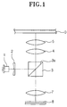
- Figure 1 is a schematic diagram illustrating a conventional optical pickup system for recording and/or reproducing data from a single optical disk.
- a light beam is emitted from a laser diode 1 and is split into three rays by a diffraction grating 2 used as a tracking servo. After passing through the diffraction grating 2, the beam is transmitted or reflected via a beam splitter 3.
- the beam splitter 3 has a coated layer 3a formed on a diagonal surface therein by which the beam is semi-transmitted or semi-reflected.
- the coated layer 3a may include a polarization coating layer on the diagonal surface for transmitting or reflecting the beam according to the type of the light polarization.
- the beam splitter 3 transmits the beams from the diffraction grating 2.
- the three rays are then reflected by the coating layer 3a formed on the diagonal surface, and are concentrated by a collimator lens 4 in the form of a parallel ray.
- the parallel ray is then focused on the recording surface of the optical disk D via an objective lens 5.
- the beam After being focused on the recording surface of the optical disk D, the beam is reflected therefrom and passes through the objective lens 5, the collimator lens 4, and the beam splitter 3, sequentially.
- An astigmatism lens 7 converges the beam passed through the beam splitter 3 to the photo-detector 8.
- the photo-detector 8 detects the beam, which is used as a data signal for reproducing and a signal for tracking and focusing control.
- the conventional optical pickup system described above can be used to record or reproduce data on or from only one type of optical disk. Further, in order to record or reproduce the data, the wavelength of the laser diode must vary depending on the density of the optical disk.
- the general arrangement of the conventional optical pickup system may be used to record or reproduce the data from various types of optical disks, different optical pickups, recording, and reproducing drives are required to record or reproduce the data on or from different optical disks, and thereby the system becomes costly and cumbersome.
- the disk drive for the CD or the CD-R needs a laser diode for emitting a laser beam of 780nm wavelength.
- the disk drive for the DVD which has higher recording density than the CD or the CD-R, needs a laser diode for emitting a laser beam of 650nm wavelength. Accordingly, different recording and/or reproducing drives need to be used to record or reproduce the data on or from different types of disks.
- a compatible optical pickup employs a laser beam source having a single chip in which laser diodes for emitting laser beams of 780nm and 650nm wavelengths are built at a close distance to each other in order to reduce the number of components, such as the beam splitter. Specifically, the laser diodes are spaced at a predetermined distance from each other, such as 100-110 ⁇ m. However, the distance between the laser diodes may create focus and tracking errors when arranging the optical pickup to emit the laser beam of 780nm wavelength by straying the beam having 650nm wavelength from an optical axis.
- a hologram is used to shift the directions of the beams to different places according to the wavelengths of the respective laser beams in a manner such that the beams are received by corresponding photo-detectors.
- Another embodiment uses a birefringence prism on the front surface of the photo-detector 8 to refract the laser beam for a DVD, which is strayed from the optical axis, to a proper location on the photo-detector 8.
- These embodiments are costly, due to the additional optical components required such as the birefringence prism and the hologram. Further, because of the increased number of components, the installation of the prism and the hologram becomes complicated.
- the present invention has been made to overcome the above-mentioned problems of the related art, and accordingly, it is an object of the present invention to provide a compatible optical disk player and data recording and/or reproducing method thereof capable of recording and/or reproducing the data on/from various types of optical disks by using a single optical pickup of simple structure.
- an apparatus a compatible disc player, and a method for use with a compatible optical disc player as set forth in the appended claims.
- an apparatus comprising: a compatible optical disk player recording and/or reproducing data on/from various types of optical disks by using a single optical pickup and by variably setting the light detecting position of a photo-detector according to the types of the optical disks being used.
- a compatible disk player comprising: a first laser diode emitting a first laser beam for use with a first type optical disk; a second laser diode emitting a second laser beam for use with a second type optical disk; a diffraction grating selectively splitting the first and the second laser beams into three rays depending on which optical disk is to be accessed, wherein the three rays comprise a main ray and two sub-rays; and a photo-detector selectively receiving the three rays of the first laser beam and the three rays of the second laser beam at different detecting portions for data recording and/or reproduction and error detection and compensation, wherein the detecting portions comprise a central detecting portion and two peripheral detecting portions.
- a compatible optical disk player comprising: a laser beam source comprising a first laser diode and a second laser diode, wherein the first laser diode emits a first laser beam of a first wavelength for recording and/or reproducing data on/from a first optical disk comprising a first recording density, and the second laser diode emits a second laser beam of a second wavelength for recording and/or reproducing the data on/from a second optical disk comprising a second recording density; a diffraction grating selectively splitting the first and the second laser beams into a main ray and two sub-rays depending on which optical disk is to be accessed; a beam splitter selectively reflecting the first laser beam toward the first optical disk and the second laser beam toward the second optical disk; an objective lens selectively focusing the first laser beam on a recording surface of the first optical disk and the second laser beam on a recording surface of the second optical disk; and a photo-detector selectively receiving the three
- a compatible disk player comprising: a laser beam source comprising a first laser diode and a second laser diode, wherein the first laser diode emits a first laser beam of a first wavelength for recording and/or reproducing data on/from a first optical disk comprising a first recording density, and the second laser diode emits a second laser beam of a second wavelength for recording and/or reproducing the data on/from a second optical disk comprising a second recording density; a diffraction grating selectively splitting the first and the second laser beams into a main ray and two sub-rays depending on which optical disk is to be accessed, wherein the diffraction grating is movable between a first position and a second position in the direction of the optical axis based upon which optical disk is to be accessed; a beam splitter selectively reflecting the first laser beam toward the first optical disk and the second laser beam toward the second optical disk; an annular cover lens selectively
- a method for a compatible optical disk player for recording and/or reproducing data comprising: emitting a first laser beam to a first optical disk; emitting a second laser beam to a second optical disk; selectively splitting the first and the second laser beams into three rays depending on which optical disk is to be accessed, wherein the three rays comprise a main ray and two sub-rays depending on which optical disk to be accessed; and selectively receiving the three rays of the first laser beam and the three rays of the second laser beam at different detecting portions for the data recording and/or reproducing and error detection and compensation, wherein the detecting portions comprise a central detecting portion and two peripheral detecting portions.
- a method for a compatible optical disk player for recording and/or reproducing data comprising: selectively emitting a first laser beam of a first wavelength for recording and/or reproducing the data on/from a first optical disk comprising a first recording density and a second laser beam of a second wavelength for recording and/or reproducing the data on/from a second optical disk comprising a second recording density; selectively splitting the first and the second laser beams into a main ray and two sub-rays depending on which optical disk is to be accessed, wherein the main ray is a 0 order light and the sub-rays are 1st order lights; selectively reflecting the first laser beam toward the first optical disk and the second laser beam toward the second optical disk; selectively focusing the first laser beam on a recording surface of the first optical disk and the second laser beam on a recording surface of the second optical disk; and selectively receiving the three rays of the first laser beam and the three rays of the second laser beam at different detecting portions to
- a method for a compatible optical disk player for recording and/or reproducing data comprising: selectively emitting a first laser beam of a first wavelength for recording and/or reproducing the data on/from a first optical disk comprising a first recording density, and a second laser beam of a second wavelength for recording and/or reproducing the data on/from a second optical disk comprising a second recording density; selectively splitting the first and the second laser beams into a main ray and two sub-rays, wherein the diffraction grating is movable between a first position and a second position in the direction of the optical axis based upon which optical disk is to be accessed; selectively reflecting the first laser beam toward the first optical disk and the second laser beam toward the second optical disk; selectively adjusting a size of the first laser beam on the first optical disk and the second laser beam on the second optical disk; selectively focusing the first laser beam on a recording surface of the first optical disk and the second laser beam on a
- FIG. 2 is a schematic diagram illustrating an optical pickup for recording and/or reproducing data on or from different types of optical disks, in accordance with an exemplary embodiment of the present invention.
- a laser source 11 includes a first laser diode 11a and a second laser diode 11b emitting a first laser beam and a second laser beam, respectively, of different wavelengths to record and/or reproduce the data on or from optical disks having different recording densities.
- the first and second laser diodes 11a, 11b may emit Soi P-polarized beams of wavelengths of 780nm and 650nm, respectively. Each beam is then used to record and/or reproduce the data on or from a CD-R D1 and DVD D2, respectively.
- the first and second laser diodes 11a, 11b are located on substantially the same optical axis, however, position aberration of 100-110 ⁇ m usually occurs when the first and second laser diodes 11a and 11b are installed.
- a diffraction grating 12 is located in front of the laser source 11.
- the diffraction grating 12 selectively splits each of the first and second laser beams emitted from the first and second laser diodes 11a, 11b into three rays including a main ray, i.e., a 0 order light, and two sub-rays, i.e., 1st order lights.
- a beam splitter 13 is located on the optical path of the first and second laser beams emitted from the first and second laser diodes 11a, 11b. The beam splitter 13 reflects or transmits an incident laser beam according to the polarization of the three rays.
- a collimator lens 14 collimates the three rays from the beam splitter 13 on the optical path of the laser beam of S or P-polarized light.
- the beam splitter 13, the collimator lens 14, an annular cover lens 16, and an objective lens 15 are coaxially arranged.
- the objective lens 15 focuses the laser beam on the recording surface of the optical disk.
- the objective lens 15 has a control section to minimize aberration on the optical disk occurring due to different thicknesses of the CD-R D1 and DVD D2.
- the annular cover lens 16 adjusts the size of the converged laser beam focused on the optical disk because the recording densities of the CD-R D1 and the DVD D2 are different. After being focused on and reflected from the optical disk D1 or D2, the laser beam is reflected and passed through the objective lens 15, the annular cover lens 16, the collimator lens 14, and the beam splitter 13, and is incident on a convergent lens 17, which is located on the optical path of the reflected beam.
- a 6-split photo-detector 18 receives the convergent beam from the convergent lens 17.
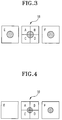
- Figure 3 is a schematic diagram illustrating the photo-detector 18 including a central detecting portion, including cells A, B, C, and D and a peripheral detecting portion including cells E and F, receiving light when the optical pickup illustrated in Figure 2 reproduces the data from the CD-R D1.
- Figure 4 is a schematic diagram illustrating the photo-detector 18 including a central detecting portion, including cells A, B, C, and D and a peripheral detecting portion including cells E and F, receiving light when the optical pickup illustrated in Figure 2 reproduces the data from the DVD D2.
- the main ray from the first laser diode 11a i.e., 0 order light
- the two sub-rays i.e., 1st order lights
- the second laser beam of the second laser diode 11b reflected on the optical disk D1 or D2 is slightly offset from the optical axis of the first laser beam of the first laser diode 11a. Accordingly, the main ray from the second laser diode 11b, i.e., the 0 order light, is incident on one of the cells E and F of the peripheral detecting portion, while one of the other two sub-rays, i.e., 1st order lights, is incident on the cells A, B, C, and D of the central detecting portion.
- the diffraction grating 12 is selectively movable on the optical axis. Accordingly, in a case that the 0 order light and 1st order lights of the first laser beam from the first laser diode 11a are incident on the photo-detector 18, moving the diffracting grating 12 with respect to the optical axis allows the 0 order light and 1st order lights of the second laser beam from the second laser diode 11b to be incident on the proper location of the photo-detector 18.
- the DVD D2 may be used by moving the diffraction grating 12 along the optical axis between a first position and a second position and setting the 0 order light of the second laser beam of the second laser diode 11b to be incident on one of the cells E and F of the peripheral detecting portion, and one of the 1st order lights to be incident on the cells A, B, C, and D of the central detecting portion while abandoning the other 1st order light.
- the first laser beam having a wavelength of 780nm is emitted from the first laser diode 11a.
- the beam includes S and P-polarized lights.
- the first and second laser diodes 11a, 11b are arranged on the same optical axis. However, because it is practically impossible to install the first and second laser diodes 11a, 11b at the same location, the second laser diode 11b is 100 - 110 ⁇ m apart from the first laser diode 11a.
- the first laser beam is split into three rays, i.e., into 0 order light and 1st order lights by the diffraction grating 12.
- the first laser beam of the S or P-polarized beam is then reflected from the beam splitter 13 toward CD-R D1 at an angle of 90 degree, and is passed through the collimator lens 14, the annular cover lens 16, and the objective lens 15.
- the first laser beam After being reflected toward the CD-R D1, the first laser beam is transmitted back through the objective lens 15, the annular cover lens 16, the collimator lens 14, and the beam splitter 13, which are coaxially disposed with respect to the optical axis. The laser beam is then converged by the convergent lens 17 and received by the photo-detector 18.
- the photo-detector 18 is a six-split photo-detector having four cells A, B, C, and D of the central detecting portion and two cells E and F of the peripheral portion. From the beam reflected from the CD-R D 1, the main ray, i.e., 0 order light, of the three rays from the first laser diode 11 is incident on the cells A, B, C, and D of the central detecting portion, while the other two rays, i.e., 1st order lights, are incident on the cells E and F of the peripheral detecting portion, respectively.
- the main ray i.e., 0 order light
- a reproduction "RF" signal, a focus error, and a tracking error are detected by using the first laser beam received by the photo-detector 18.
- the second laser beam having a wavelength of 650nm is emitted from the second laser diode 11b.
- the second laser beam has an S-polarized light.
- the second laser diode 11b is initially 100 ⁇ 110 ⁇ m apart from the first laser diode 11a.
- the second laser beam emitted from the second laser diode 11b is split into three rays, i.e., into 0 order light and + 1st order lights, by the diffraction grating 12.
- the second laser beam having the S or P-polarized beam emitted from the second laser diode 11b is reflected toward the DVD D2 at an angle of 90 as it passes through the beam splitter 13. After being reflected from the DVD D2, the laser beam is transmitted back in the direction of the optical axis and is converged by the convergent lens 17 and received by the photo-detector 18.
- the second laser beam received by the photo-detector 18 has an optical axis different from the optical axis of the first laser beam due to the distance between the first laser diode 11a and the second laser diode 11b. Accordingly, as shown in Figure 4, the main ray, i.e., 0 order light, of the second laser beam reflected from the DVD D2 is incident on one of the cells E and F of the peripheral detecting portion. Also, among the two sub-rays, i.e. 1st order lights, one first order light is strayed from the cells E and F of the peripheral portion, while the other first order light is incident on the cells A, B, C, and D of the central detecting portion.
- the main ray i.e., 0 order light
- the positions of the first and second laser diodes 11a and 11b, with respect to each other, are different depending on the particular type of device being used.
- an adjustment error is performed according to the initial positions of both the first and second laser diodes 11a and 11b. Because the diffraction grating 12 may be moved along the direction of the optical axis, the diffraction grating 12 may be adjusted so that the 0 order light and the 1st order lights may be incident on the proper location on the photo-detector 18.
- a method for detecting the reproduction "RF" signal, a focus error, and a tracking error while using the DVD disk D2 with the second laser beam received on the photo-detector 18 is described hereinafter.
- a single optical pickup can record and/or reproduce the data on or from the various types of the disks, such as CD-R D1 and DVD D2.
- the present invention has been developed to overcome the above-mentioned problems of current recording and/or reproducing drives.
- the present invention provides a compatible optical disk player and the data recording and/or reproducing method capable of recording and/or reproducing the data on or from different types of optical disks D 1 and D2 with a single optical pickup by variably setting the light detecting position on the photo-detector 18 according to the type of disk D1, D2 being used.
- the main ray of the first laser beam emitted from the first laser source is incident on the cells A, B, C, and D of the central detecting portion of the photo-detector 18, while the two sub-rays are incident on the cells E and F of the peripheral detecting portion of the photo detector 18.
- the respective optical elements are adjusted so that the main ray of the second laser beam, which is emitted from the second laser source positioned at a slight distance from the first laser source, can be incident on one of the cells E and F of the peripheral detecting portion of the photo-detector 18, while one of the two sub- rays are incident on the cells A, B, C, and D of the central detecting portion.
- the main ray of the first laser beam on the cells A, B, C, and D of the central detecting portion is processed by the focusing servo to determine a focus error signal and also to record and/or reproduce the data.
- the sub-rays of the first laser beam on the cells E and F of the peripheral detecting portion are used by the tracking servo to determine the tracking error signal.
- the main ray of the second laser beam on one of the cells E and F of the peripheral detecting portion is used to record and/or reproduce the data.
- One of the two sub-rays of the second laser beam on the cells A, B, C, and D is processed by the focusing servo and the tracking servo.
- An error (100 ⁇ 110 ⁇ m) occurs due to the distances between initial setting positions of the first and second laser beam sources. Such an error can be compensated by moving the diffraction grating 12 forward or backward.
Landscapes
- Physics & Mathematics (AREA)
- Optics & Photonics (AREA)
- Optical Head (AREA)
- Optical Recording Or Reproduction (AREA)
Applications Claiming Priority (2)
| Application Number | Priority Date | Filing Date | Title |
|---|---|---|---|
| KR2000026782 | 2000-05-18 | ||
| KR1020000026782A KR100341335B1 (ko) | 2000-05-18 | 2000-05-18 | 광디스크 플레이어 및 그 기록 또는 재생방법 |
Publications (3)
| Publication Number | Publication Date |
|---|---|
| EP1156483A2 true EP1156483A2 (de) | 2001-11-21 |
| EP1156483A3 EP1156483A3 (de) | 2004-09-29 |
| EP1156483B1 EP1156483B1 (de) | 2006-12-20 |
Family
ID=19669134
Family Applications (1)
| Application Number | Title | Priority Date | Filing Date |
|---|---|---|---|
| EP01304149A Expired - Lifetime EP1156483B1 (de) | 2000-05-18 | 2001-05-08 | Kompatibler optischer Plattenspieler und Verfahren zur Datenaufzeichnung und -Wiedergabe |
Country Status (8)
| Country | Link |
|---|---|
| US (1) | US7230904B2 (de) |
| EP (1) | EP1156483B1 (de) |
| JP (1) | JP3581329B2 (de) |
| KR (1) | KR100341335B1 (de) |
| CN (1) | CN1186770C (de) |
| DE (1) | DE60125275T2 (de) |
| MY (1) | MY134813A (de) |
| TW (1) | TWI259458B (de) |
Cited By (1)
| Publication number | Priority date | Publication date | Assignee | Title |
|---|---|---|---|---|
| WO2004032126A1 (en) * | 2002-10-02 | 2004-04-15 | Koninklijke Philips Electronics N.V. | Optical scanning device with two three-spot gratings |
Families Citing this family (16)
| Publication number | Priority date | Publication date | Assignee | Title |
|---|---|---|---|---|
| JP3785349B2 (ja) * | 2001-11-09 | 2006-06-14 | ファナック株式会社 | シミュレーション装置 |
| KR100464427B1 (ko) * | 2002-08-12 | 2005-01-03 | 삼성전자주식회사 | 광픽업 및 이를 채용한 광 기록 및/또는 재생기기 |
| KR20040022766A (ko) * | 2002-09-07 | 2004-03-18 | 삼성전자주식회사 | 광픽업장치 및 이를 채용하는 광기록매체 드라이브 장치및 이를 이용한 트래킹 서보 제어방법 |
| JP2005018897A (ja) * | 2003-06-25 | 2005-01-20 | Toshiba Corp | 光学ヘッド及び光ディスクドライブ |
| US8108429B2 (en) | 2004-05-07 | 2012-01-31 | Quest Software, Inc. | System for moving real-time data events across a plurality of devices in a network for simultaneous data protection, replication, and access services |
| US7565661B2 (en) | 2004-05-10 | 2009-07-21 | Siew Yong Sim-Tang | Method and system for real-time event journaling to provide enterprise data services |
| US7680834B1 (en) | 2004-06-08 | 2010-03-16 | Bakbone Software, Inc. | Method and system for no downtime resychronization for real-time, continuous data protection |
| US7492442B2 (en) * | 2004-08-27 | 2009-02-17 | Asml Holding N.V. | Adjustable resolution interferometric lithography system |
| US7979404B2 (en) | 2004-09-17 | 2011-07-12 | Quest Software, Inc. | Extracting data changes and storing data history to allow for instantaneous access to and reconstruction of any point-in-time data |
| US7904913B2 (en) | 2004-11-02 | 2011-03-08 | Bakbone Software, Inc. | Management interface for a system that provides automated, real-time, continuous data protection |
| US7788521B1 (en) | 2005-07-20 | 2010-08-31 | Bakbone Software, Inc. | Method and system for virtual on-demand recovery for real-time, continuous data protection |
| US7689602B1 (en) | 2005-07-20 | 2010-03-30 | Bakbone Software, Inc. | Method of creating hierarchical indices for a distributed object system |
| US8131723B2 (en) | 2007-03-30 | 2012-03-06 | Quest Software, Inc. | Recovering a file system to any point-in-time in the past with guaranteed structure, content consistency and integrity |
| US8364648B1 (en) | 2007-04-09 | 2013-01-29 | Quest Software, Inc. | Recovering a database to any point-in-time in the past with guaranteed data consistency |
| US8085645B2 (en) * | 2009-03-13 | 2011-12-27 | Panasonic Corporation | Optical pickup device and optical disk apparatus |
| KR20140106054A (ko) * | 2013-02-25 | 2014-09-03 | 도시바삼성스토리지테크놀러지코리아 주식회사 | 광픽업 및 이를 채용한 광정보저장매체 시스템 |
Family Cites Families (23)
| Publication number | Priority date | Publication date | Assignee | Title |
|---|---|---|---|---|
| NL8101932A (nl) | 1981-04-21 | 1982-11-16 | Philips Nv | Inrichting voor het inschrijven en uitlezen van informatiesporen in een optische registratiedrager. |
| JP2583273B2 (ja) * | 1988-04-04 | 1997-02-19 | 株式会社日本コンラックス | 光学的情報記録再生方法および装置 |
| US5615200A (en) * | 1992-09-10 | 1997-03-25 | Kabushiki Kaisha Toshiba | Light beam shaping device to change an anisotropic beam to an isotropic beam for reducing the size of an optical head |
| KR970004210B1 (ko) | 1994-06-10 | 1997-03-26 | 엘지전자 주식회사 | 광픽업 장치 |
| JPH0830993A (ja) | 1994-07-19 | 1996-02-02 | Hitachi Ltd | トラッキング誤差検出方式およびそれを用いた光ディスク装置 |
| US5717674A (en) * | 1995-06-30 | 1998-02-10 | Sanyo Electrics Co., Ltd. | Three-beam generating diffraction grating, transmission type holographic optical element and optical pickup apparatus using the same |
| KR100269105B1 (ko) * | 1995-12-07 | 2000-10-16 | 윤종용 | 두께가다른디스크의호환이가능한기록재생용광픽업 |
| KR0183817B1 (ko) | 1996-01-30 | 1999-04-15 | 김광호 | 호환형 광픽업장치 |
| JPH09288842A (ja) * | 1996-04-19 | 1997-11-04 | Sony Corp | 光学ピックアップ及び光ディスク装置 |
| JP3454017B2 (ja) | 1996-04-19 | 2003-10-06 | ソニー株式会社 | 光学ピックアップ及び光ディスク装置 |
| JP3244442B2 (ja) | 1996-08-30 | 2002-01-07 | 三洋電機株式会社 | 光再生装置 |
| CN1258760C (zh) * | 1996-09-27 | 2006-06-07 | 三洋电机株式会社 | 波长选择性衍射光栅 |
| JP3301765B2 (ja) * | 1996-10-31 | 2002-07-15 | 三洋電機株式会社 | 光ピックアップ装置 |
| US6181667B1 (en) * | 1997-03-14 | 2001-01-30 | Sanyo Electric Co., Ltd. | Optical pickup apparatus capable of suppressing offset of a tracking error signal |
| JP3653923B2 (ja) * | 1997-03-19 | 2005-06-02 | ソニー株式会社 | 記録再生装置および方法 |
| JPH10308031A (ja) * | 1997-05-06 | 1998-11-17 | Sankyo Seiki Mfg Co Ltd | 光ピックアップ装置 |
| JP3687939B2 (ja) * | 1997-05-22 | 2005-08-24 | パイオニア株式会社 | 光ピックアップ装置 |
| JP3778316B2 (ja) * | 1997-05-22 | 2006-05-24 | パイオニア株式会社 | 光ピックアップ装置 |
| US6195315B1 (en) * | 1997-07-11 | 2001-02-27 | Ricoh Company, Ltd. | Optical disk apparatus compatible with different types of mediums |
| JP2002515624A (ja) * | 1998-05-13 | 2002-05-28 | コーニンクレッカ フィリップス エレクトロニクス エヌ ヴィ | 記録担体を光学的に走査する装置 |
| JP2000030288A (ja) * | 1998-07-08 | 2000-01-28 | Pioneer Electron Corp | 光ピックアップ素子 |
| JP2000123403A (ja) * | 1998-10-19 | 2000-04-28 | Victor Co Of Japan Ltd | 光ピックアップ及び光デバイス |
| TW411454B (en) | 1998-10-28 | 2000-11-11 | Ind Tech Res Inst | Optical read/write head for dual wavelength |
-
2000
- 2000-05-18 KR KR1020000026782A patent/KR100341335B1/ko not_active Expired - Fee Related
-
2001
- 2001-05-02 JP JP2001135610A patent/JP3581329B2/ja not_active Expired - Fee Related
- 2001-05-03 TW TW090110602A patent/TWI259458B/zh not_active IP Right Cessation
- 2001-05-08 EP EP01304149A patent/EP1156483B1/de not_active Expired - Lifetime
- 2001-05-08 DE DE60125275T patent/DE60125275T2/de not_active Expired - Lifetime
- 2001-05-10 US US09/852,002 patent/US7230904B2/en not_active Expired - Fee Related
- 2001-05-15 MY MYPI20012283A patent/MY134813A/en unknown
- 2001-05-15 CN CNB011176717A patent/CN1186770C/zh not_active Expired - Fee Related
Cited By (1)
| Publication number | Priority date | Publication date | Assignee | Title |
|---|---|---|---|---|
| WO2004032126A1 (en) * | 2002-10-02 | 2004-04-15 | Koninklijke Philips Electronics N.V. | Optical scanning device with two three-spot gratings |
Also Published As
| Publication number | Publication date |
|---|---|
| MY134813A (en) | 2007-12-31 |
| KR100341335B1 (ko) | 2002-06-22 |
| JP3581329B2 (ja) | 2004-10-27 |
| US7230904B2 (en) | 2007-06-12 |
| EP1156483A3 (de) | 2004-09-29 |
| EP1156483B1 (de) | 2006-12-20 |
| TWI259458B (en) | 2006-08-01 |
| US20010043522A1 (en) | 2001-11-22 |
| CN1186770C (zh) | 2005-01-26 |
| KR20010105057A (ko) | 2001-11-28 |
| JP2001357526A (ja) | 2001-12-26 |
| DE60125275T2 (de) | 2007-05-10 |
| DE60125275D1 (de) | 2007-02-01 |
| CN1332448A (zh) | 2002-01-23 |
Similar Documents
| Publication | Publication Date | Title |
|---|---|---|
| EP1001414B1 (de) | Kompatibles optisches Abtastgerät | |
| EP1156483B1 (de) | Kompatibler optischer Plattenspieler und Verfahren zur Datenaufzeichnung und -Wiedergabe | |
| US6392977B2 (en) | Optical pickup with a hologram to limit the aperture of two light beams with different wavelengths | |
| KR100438701B1 (ko) | 호환형 광픽업 및 그 광축을 맞추기 위한 조정방법 | |
| KR100716938B1 (ko) | 광픽업장치 | |
| KR100224621B1 (ko) | 두께가 다른 디스크 호환을 위한 기록재생용 광픽업 | |
| US20080049581A1 (en) | Optical pick-up | |
| JP2559011B2 (ja) | 光ヘッド | |
| KR20080078417A (ko) | 호환형 광픽업 및 이를 채용한 광정보저장매체 시스템 | |
| US7136332B2 (en) | Optical pickup device | |
| JPH10208267A (ja) | 光ヘッドおよび光ディスク装置 | |
| JP2001023222A (ja) | 光ピックアップ装置 | |
| US7719949B2 (en) | Optical head | |
| KR100215455B1 (ko) | 포커스에러를 검출하는 dvd/cd겸용 광픽업시스템 | |
| KR100370205B1 (ko) | 호환형 광픽업장치 | |
| US7911920B2 (en) | Optical pick-up apparatus and method for multi-optical disk type recording/reproducing | |
| JPH0944887A (ja) | 光ピックアップ及び再生装置 | |
| JPH10112056A (ja) | 光ピックアップ | |
| US20060140104A1 (en) | Optical pickup and optical disk apparatus | |
| US20080285427A1 (en) | Optical pick-up and disc apparatus having the same | |
| US20060221783A1 (en) | Optical head and optical disc apparatus | |
| KR19990057682A (ko) | 호환형 광픽업장치 | |
| US20060158995A1 (en) | Optical pickup device and focusing control method of the same | |
| JPH10269612A (ja) | 光ピックアップ | |
| JPH08329515A (ja) | 光学ピックアップ装置 |
Legal Events
| Date | Code | Title | Description |
|---|---|---|---|
| PUAI | Public reference made under article 153(3) epc to a published international application that has entered the european phase |
Free format text: ORIGINAL CODE: 0009012 |
|
| 17P | Request for examination filed |
Effective date: 20010518 |
|
| AK | Designated contracting states |
Kind code of ref document: A2 Designated state(s): AT BE CH CY DE DK ES FI FR GB GR IE IT LI LU MC NL PT SE TR |
|
| AX | Request for extension of the european patent |
Free format text: AL;LT;LV;MK;RO;SI |
|
| PUAL | Search report despatched |
Free format text: ORIGINAL CODE: 0009013 |
|
| AK | Designated contracting states |
Kind code of ref document: A3 Designated state(s): AT BE CH CY DE DK ES FI FR GB GR IE IT LI LU MC NL PT SE TR |
|
| AX | Request for extension of the european patent |
Extension state: AL LT LV MK RO SI |
|
| 17Q | First examination report despatched |
Effective date: 20050318 |
|
| AKX | Designation fees paid |
Designated state(s): DE GB NL |
|
| GRAP | Despatch of communication of intention to grant a patent |
Free format text: ORIGINAL CODE: EPIDOSNIGR1 |
|
| GRAS | Grant fee paid |
Free format text: ORIGINAL CODE: EPIDOSNIGR3 |
|
| GRAA | (expected) grant |
Free format text: ORIGINAL CODE: 0009210 |
|
| AK | Designated contracting states |
Kind code of ref document: B1 Designated state(s): DE GB NL |
|
| REG | Reference to a national code |
Ref country code: GB Ref legal event code: FG4D |
|
| REF | Corresponds to: |
Ref document number: 60125275 Country of ref document: DE Date of ref document: 20070201 Kind code of ref document: P |
|
| PLBE | No opposition filed within time limit |
Free format text: ORIGINAL CODE: 0009261 |
|
| STAA | Information on the status of an ep patent application or granted ep patent |
Free format text: STATUS: NO OPPOSITION FILED WITHIN TIME LIMIT |
|
| 26N | No opposition filed |
Effective date: 20070921 |
|
| PGFP | Annual fee paid to national office [announced via postgrant information from national office to epo] |
Ref country code: DE Payment date: 20130423 Year of fee payment: 13 Ref country code: GB Payment date: 20130426 Year of fee payment: 13 |
|
| PGFP | Annual fee paid to national office [announced via postgrant information from national office to epo] |
Ref country code: NL Payment date: 20130423 Year of fee payment: 13 |
|
| REG | Reference to a national code |
Ref country code: DE Ref legal event code: R119 Ref document number: 60125275 Country of ref document: DE |
|
| REG | Reference to a national code |
Ref country code: NL Ref legal event code: V1 Effective date: 20141201 |
|
| GBPC | Gb: european patent ceased through non-payment of renewal fee |
Effective date: 20140508 |
|
| PG25 | Lapsed in a contracting state [announced via postgrant information from national office to epo] |
Ref country code: NL Free format text: LAPSE BECAUSE OF NON-PAYMENT OF DUE FEES Effective date: 20141201 |
|
| REG | Reference to a national code |
Ref country code: DE Ref legal event code: R119 Ref document number: 60125275 Country of ref document: DE Effective date: 20141202 |
|
| PG25 | Lapsed in a contracting state [announced via postgrant information from national office to epo] |
Ref country code: DE Free format text: LAPSE BECAUSE OF NON-PAYMENT OF DUE FEES Effective date: 20141202 |
|
| PG25 | Lapsed in a contracting state [announced via postgrant information from national office to epo] |
Ref country code: GB Free format text: LAPSE BECAUSE OF NON-PAYMENT OF DUE FEES Effective date: 20140508 |