EP1156496A1 - Compose isotrope et son procede de preparation, aimant lie isotrope, machine rotative et rouleau a aimant - Google Patents
Compose isotrope et son procede de preparation, aimant lie isotrope, machine rotative et rouleau a aimant Download PDFInfo
- Publication number
- EP1156496A1 EP1156496A1 EP00977909A EP00977909A EP1156496A1 EP 1156496 A1 EP1156496 A1 EP 1156496A1 EP 00977909 A EP00977909 A EP 00977909A EP 00977909 A EP00977909 A EP 00977909A EP 1156496 A1 EP1156496 A1 EP 1156496A1
- Authority
- EP
- European Patent Office
- Prior art keywords
- resin
- isotropic
- magnet
- bonded
- magnet powder
- Prior art date
- Legal status (The legal status is an assumption and is not a legal conclusion. Google has not performed a legal analysis and makes no representation as to the accuracy of the status listed.)
- Withdrawn
Links
Images











Classifications
-
- G—PHYSICS
- G03—PHOTOGRAPHY; CINEMATOGRAPHY; ANALOGOUS TECHNIQUES USING WAVES OTHER THAN OPTICAL WAVES; ELECTROGRAPHY; HOLOGRAPHY
- G03G—ELECTROGRAPHY; ELECTROPHOTOGRAPHY; MAGNETOGRAPHY
- G03G15/00—Apparatus for electrographic processes using a charge pattern
- G03G15/06—Apparatus for electrographic processes using a charge pattern for developing
- G03G15/08—Apparatus for electrographic processes using a charge pattern for developing using a solid developer, e.g. powder developer
- G03G15/09—Apparatus for electrographic processes using a charge pattern for developing using a solid developer, e.g. powder developer using magnetic brush
- G03G15/0921—Details concerning the magnetic brush roller structure, e.g. magnet configuration
-
- H—ELECTRICITY
- H01—ELECTRIC ELEMENTS
- H01F—MAGNETS; INDUCTANCES; TRANSFORMERS; SELECTION OF MATERIALS FOR THEIR MAGNETIC PROPERTIES
- H01F1/00—Magnets or magnetic bodies characterised by the magnetic materials therefor; Selection of materials for their magnetic properties
- H01F1/01—Magnets or magnetic bodies characterised by the magnetic materials therefor; Selection of materials for their magnetic properties of inorganic materials
- H01F1/03—Magnets or magnetic bodies characterised by the magnetic materials therefor; Selection of materials for their magnetic properties of inorganic materials characterised by their coercivity
- H01F1/032—Magnets or magnetic bodies characterised by the magnetic materials therefor; Selection of materials for their magnetic properties of inorganic materials characterised by their coercivity of hard-magnetic materials
- H01F1/04—Magnets or magnetic bodies characterised by the magnetic materials therefor; Selection of materials for their magnetic properties of inorganic materials characterised by their coercivity of hard-magnetic materials metals or alloys
- H01F1/06—Magnets or magnetic bodies characterised by the magnetic materials therefor; Selection of materials for their magnetic properties of inorganic materials characterised by their coercivity of hard-magnetic materials metals or alloys in the form of particles, e.g. powder
- H01F1/08—Magnets or magnetic bodies characterised by the magnetic materials therefor; Selection of materials for their magnetic properties of inorganic materials characterised by their coercivity of hard-magnetic materials metals or alloys in the form of particles, e.g. powder pressed, sintered, or bound together
-
- H—ELECTRICITY
- H01—ELECTRIC ELEMENTS
- H01F—MAGNETS; INDUCTANCES; TRANSFORMERS; SELECTION OF MATERIALS FOR THEIR MAGNETIC PROPERTIES
- H01F1/00—Magnets or magnetic bodies characterised by the magnetic materials therefor; Selection of materials for their magnetic properties
- H01F1/01—Magnets or magnetic bodies characterised by the magnetic materials therefor; Selection of materials for their magnetic properties of inorganic materials
- H01F1/03—Magnets or magnetic bodies characterised by the magnetic materials therefor; Selection of materials for their magnetic properties of inorganic materials characterised by their coercivity
- H01F1/032—Magnets or magnetic bodies characterised by the magnetic materials therefor; Selection of materials for their magnetic properties of inorganic materials characterised by their coercivity of hard-magnetic materials
- H01F1/04—Magnets or magnetic bodies characterised by the magnetic materials therefor; Selection of materials for their magnetic properties of inorganic materials characterised by their coercivity of hard-magnetic materials metals or alloys
- H01F1/047—Alloys characterised by their composition
- H01F1/053—Alloys characterised by their composition containing rare earth metals
- H01F1/055—Alloys characterised by their composition containing rare earth metals and magnetic transition metals, e.g. SmCo5
- H01F1/059—Alloys characterised by their composition containing rare earth metals and magnetic transition metals, e.g. SmCo5 and Va elements, e.g. Sm2Fe17N2
-
- H—ELECTRICITY
- H02—GENERATION; CONVERSION OR DISTRIBUTION OF ELECTRIC POWER
- H02K—DYNAMO-ELECTRIC MACHINES
- H02K1/00—Details of the magnetic circuit
- H02K1/02—Details of the magnetic circuit characterised by the magnetic material
-
- H—ELECTRICITY
- H02—GENERATION; CONVERSION OR DISTRIBUTION OF ELECTRIC POWER
- H02K—DYNAMO-ELECTRIC MACHINES
- H02K1/00—Details of the magnetic circuit
- H02K1/06—Details of the magnetic circuit characterised by the shape, form or construction
- H02K1/22—Rotating parts of the magnetic circuit
- H02K1/27—Rotor cores with permanent magnets
- H02K1/2706—Inner rotors
- H02K1/272—Inner rotors the magnetisation axis of the magnets being perpendicular to the rotor axis
- H02K1/2726—Inner rotors the magnetisation axis of the magnets being perpendicular to the rotor axis the rotor consisting of a single magnet or two or more axially juxtaposed single magnets
-
- H—ELECTRICITY
- H02—GENERATION; CONVERSION OR DISTRIBUTION OF ELECTRIC POWER
- H02K—DYNAMO-ELECTRIC MACHINES
- H02K15/00—Processes or apparatus specially adapted for manufacturing, assembling, maintaining or repairing of dynamo-electric machines
- H02K15/02—Processes or apparatus specially adapted for manufacturing, assembling, maintaining or repairing of dynamo-electric machines of stator or rotor bodies
- H02K15/03—Processes or apparatus specially adapted for manufacturing, assembling, maintaining or repairing of dynamo-electric machines of stator or rotor bodies having permanent magnets
-
- H—ELECTRICITY
- H02—GENERATION; CONVERSION OR DISTRIBUTION OF ELECTRIC POWER
- H02K—DYNAMO-ELECTRIC MACHINES
- H02K21/00—Synchronous motors having permanent magnets; Synchronous generators having permanent magnets
- H02K21/12—Synchronous motors having permanent magnets; Synchronous generators having permanent magnets with stationary armatures and rotating magnets
- H02K21/24—Synchronous motors having permanent magnets; Synchronous generators having permanent magnets with stationary armatures and rotating magnets with magnets axially facing the armatures, e.g. hub-type cycle dynamos
-
- H—ELECTRICITY
- H04—ELECTRIC COMMUNICATION TECHNIQUE
- H04R—LOUDSPEAKERS, MICROPHONES, GRAMOPHONE PICK-UPS OR LIKE ACOUSTIC ELECTROMECHANICAL TRANSDUCERS; ELECTRIC HEARING AIDS; PUBLIC ADDRESS SYSTEMS
- H04R9/00—Transducers of moving-coil, moving-strip, or moving-wire type
- H04R9/02—Details
- H04R9/025—Magnetic circuit
Definitions
- the present invention relates to a high-performance, sheet-shaped, isotropic, resin-bonded R-T-N magnet having decreased surface roughness as compared with the conventional resin-bonded magnets, which is useful for wide ranges of magnet applications such as various rotating machines, magnet rolls for electromagnetic developing-type printers and copiers, various actuators such as voice coil motors and linear motors, etc., audio speakers, buzzers, sensors, magnets for absorption or generation of magnetic field, etc.
- the present invention also relates to a high-performance, sheet-shaped, isotropic, resin-bonded magnet having decreased surface roughness as compared with the conventional resin-bonded magnets, which substantially comprises R-T-N isotropic magnet powder, R'-T'-B isotropic magnet powder comprising an R' 2 T' 14 B-type intermetallic compound as a main phase and a binder.
- the present invention further relates to a high-performance, ring-shaped or cylindrical, isotropic, resin-bonded R-T-N magnet, which is improved in roundness of the external or internal peripheral surface as compared with the conventional resin-bonded magnets.
- the present invention further relates to a high-performance, ring-shaped or cylindrical, isotropic, resin-bonded magnet substantially comprising R-T-N isotropic magnet powder, R'-T'-B isotropic magnet powder and a binder, which is improved in roundness of the external or internal peripheral surface as compared with the conventional resin-bonded magnets.
- the present invention further relates to a high-performance, sheet-shaped, isotropic, resin-bonded (Sm, La)-T-N magnet, which is improved in magnetizability as compared with the conventional resin-bonded magnets.
- the present invention further relates to a high-performance, isotropic, resin-bonded, magnet substantially comprising isotropic (Sm, La)-T-N magnet powder having improved magnetizability compared with the conventional resin-bonded magnets, R'-T'-B isotropic magnet powder, and a binder.
- the present invention further relates to a rotating machine and a magnet roll both constituted by such an isotropic, resin-bonded magnet.
- the present invention further relates to a compound for such an isotropic, resin-bonded magnet and a method for producing it.
- Isotropic Nd-Fe-B magnet powder comprising an Nd 2 Fe 14 B-type intermetallic compound (see U. S. Patent No. 4,496,395) as a main phase is widely used for resin-bonded rare earth magnets.
- This magnet powder is obtained by rapid quenching a molten Nd-Fe-B alloy of a predetermined composition and heat-treating the resultant flakes under predetermined conditions, if necessary.
- this magnet powder is poor in corrosion resistance and magnetizability.
- Magnetizability is evaluated by magnetic properties such as maximum energy product (BH) max , etc., when magnetized in a magnetizing field of 1.9 MA/m (25 kOe) or less at room temperature.
- the conventional, isotropic, resin-bonded rare earth magnets are poor in magnetizability, needing improvement in magnetizability.
- Why the intensity of a magnetizing field is limited to 1.9 MA/m (25 kOe) or less is that for instance, when an isotropic, resin-bonded rare earth magnet is magnetized in a state of being assembled in a predetermined magnetic circuit, it is difficult to be magnetized in a magnetizing field of more than 1.9 MA/m (25 kOe) most of the time in an industrial production.
- Isotropic, resin-bonded rare earth magnets are required to have high performance (small thickness) as well as high dimensional accuracy.
- the isotropic, resin-bonded rare earth magnet and a vibration plate are disposed in opposite each other via a magnetic gap, which is changeable to control the quality of sound of the electronic buzzer.
- isotropic, resin-bonded rare earth magnets assembled in the electronic buzzers are required to have high dimensional accuracy.
- isotropic, resin-bonded rare earth magnets for spindle motors constituting hard disc drives for computers, motors for CD-ROM and DVD (digital video disc) drives, etc. are required to have high magnetic properties and dimensional accuracy enabling them to be made thinner.
- long means that a resin-bonded magnet is as long as 10 mm or more, preferably 20 mm or more in an axial direction.
- thick means that a resin-bonded magnet is as thin as 3 mm or less, preferably 2 mm or less.
- the sheet-shaped, isotropic, resin-bonded rare earth magnet having a thickness of 5mm or less, preferably 2mm or less is used for a field magnet for a rotating machine
- the resin-bonded magnet had poor surface roughness (maximum roughness R max )
- the sheet-shaped, resin-bonded magnet is usually in a wound state, it is important to that the sheet-shaped, resin-bonded magnet has increased cracking resistance (durability) when bended at a predetermined radius of curvature.
- an object of the present invention is to solve the problems of the conventional art, thereby providing a high-performance, sheet-shaped, isotropic, resin-bonded R-T-N magnet, wherein R is at least one of rare earth elements including Y, Sm being indispensable, T is Fe or Fe and Co, and having a decreased surface roughness (maximum roughness: R max ) compared with the conventional resin-bonded magnet.
- Another object of the present invention is to provide a high-performance, sheet-shaped, isotropic, resin-bonded magnet comprising R-T-N isotropic magnet powder, R'-T'-B isotropic magnet powder substantially comprising as main phase an R' 2 T' 14 B-type intermetallic compound, wherein R' is at least one of rare earth element including Y, Nd being indispensable, and T' is Fe or Fe and Co, and a binder, and having a decreased surface roughness (maximum roughness: R max ) compared with the conventional resin-bonded magnet.
- a further object of the present invention is to provide a high-performance, ring-shaped or cylindrical, isotropic, resin-bonded R-T-N magnet having an improved roundness in an external or internal peripheral surface compared with the conventional resin-bonded magnet.
- a still further object of the present invention is to provide a high-performance, ring-shaped or cylindrical, isotropic, resin-bonded magnet comprising R-T-N isotropic magnet powder, R'-T'-B isotropic magnet powder and a binder substantially, and having an improved roundness of in an external or internal peripheral surface compared with the conventional resin-bonded magnet.
- a still further object of the present invention is to provide a high-performance, sheet-shaped, isotropic, resin-bonded, (Sm, La)-T-N-type magnet having an improved magnetizability compared with the conventional resin-bonded magnet.
- a still further object of the present invention is to provide a high-performance, isotropic, resin-bonded magnet substantially comprising an (Sm, La) -T-N isotropic magnet powder having an improved magnetizability compared with the conventional resin-bonded magnet, R'-T'-B isotropic magnet powder and a binder.
- a still further object of the present invention is to provide a rotating machine and magnet roll both constituted by such an isotropic, resin-bonded magnet.
- a still further object of the present invention is to provide a compound and the method of producing it for such an isotropic, resin-bonded magnet.
- the isotropic, resin-bonded magnet according to an embodiment of the present invention substantially comprises R-T-N magnet powder having a main component composition represented by R ⁇ T 100- ( ⁇ + ⁇ + ⁇ + ⁇ ) M ⁇ B ⁇ N ⁇ by atomic %, wherein R is at least one of rare earth elements including Y, Sm being indispensable, T is Fe or Fe and Co, M is at least one element selected from the group consisting of Al, Ti, V, Cr, Mn, Cu, Ga, Zr, Nb, Mo, Hf, Ta, W and Zn, and ⁇ , ⁇ , ⁇ and ⁇ satisfy 4 ⁇ 15, 0 ⁇ 10, 0 ⁇ 4 and 4 ⁇ 30, respectively, and a binder, in the form of a sheet-shaped, molded product having a thickness of 0.1-5 mm, with the maximum roughness (R max ) defined by JIS B 0601 decreased to 15 ⁇ m or less.
- R is at least one of rare earth elements including Y, Sm being indispensable
- T is Fe or Fe and
- the sheet-shaped, isotropic, resin-bonded magnet of the present invention is suitable for magnet appliances having small magnetic gaps.
- the isotropic, resin-bonded magnet according to another embodiment of the present invention substantially comprises (a) R-T-N magnet powder having a main component composition represented by R ⁇ T 100-( ⁇ + ⁇ + ⁇ + ⁇ ) M ⁇ B ⁇ N ⁇ by atomic %, wherein R is at least one of rare earth elements including Y, Sm being indispensable, T is Fe or Fe and Co, M is at least one element selected from the group consisting of Al, Ti, V, Cr, Mn, Cu, Ga, Zr, Nb, Mo, Hf, Ta, W and Zn, and ⁇ , ⁇ , ⁇ and ⁇ satisfy 4 ⁇ 15, 0 ⁇ 10, 0 ⁇ 4 and 4 ⁇ 30, respectively, (b) R'-T'-B magnet powder comprising as a main phase an R' 2 T' 14 B-type intermetallic compound, wherein R' is at least one of rare earth elements including Y, Nd being indispensable, and T' is Fe or Fe and Co, and having an average crystal grain size of 0.01-0.5 ⁇ m
- the sheet-shaped, isotropic, resin-bonded magnet of the present invention has high (BH) max and is suitable for magnet appliances having small magnetic gaps.
- the isotropic, resin-bonded magnet substantially comprises R-T-N magnet powder having a main component composition represented by R ⁇ T 100-( ⁇ + ⁇ + ⁇ + ⁇ ) M ⁇ B ⁇ N ⁇ by atomic %, wherein R is at least one of rare earth elements including Y, Sm being indispensable, T is Fe or Fe and Co, M is at least one element selected from the group consisting of Al, Ti, V, Cr, Mn, Cu, Ga, Zr, Nb, Mo, Hf, Ta, W and Zn, and ⁇ , ⁇ , ⁇ and ⁇ satisfy 4 ⁇ 15, 0 ⁇ 10, 0 ⁇ 4 and 4 ⁇ 30, respectively, and a binder, in the form of a ring-shaped or cylindrical, molded product with the deviation of its outer diameter from a diameter of a true circle decreased to 15 ⁇ m or less.
- R is at least one of rare earth elements including Y, Sm being indispensable
- T is Fe or Fe and Co
- M is at least one element selected from the group consisting of Al
- the deviation of its inner diameter from a diameter of a true circle can be decreased to 15 ⁇ m or less.
- the ring-shaped or cylindrical, isotropic, resin-bonded magnet of the present invention is suitable for magnet appliances having small magnetic gaps.
- the isotropic, resin-bonded magnet substantially comprises (a) R-T-N magnet powder having a main component composition represented by R ⁇ T 100-( ⁇ + ⁇ + ⁇ + ⁇ ) M ⁇ B ⁇ N ⁇ by atomic %, wherein R is at least one of rare earth elements including Y, Sm being indispensable, T is Fe or Fe and Co, M is at least one element selected from the group consisting of Al, Ti, V, Cr, Mn, Cu, Ga, Zr, Nb, Mo, Hf, Ta, W and Zn, and ⁇ , ⁇ , ⁇ and ⁇ satisfy 4 ⁇ 15, 0 ⁇ 10, 0 ⁇ 4 and 4 ⁇ 30, respectively, (b) R'-T'-B magnet powder comprising as a main phase R' 2 T' 14 B-type intermetallic compound, wherein R' is at least one of rare earth elements including Y, Nd being indispensable, and T' is Fe or Fe and Co, and having an average crystal grain size of 0.01-0.5 ⁇
- the deviation of its inner diameter from a diameter of a true circle can be decreased to 15 ⁇ m or less.
- the ring-shaped or cylindrical, isotropic, resin-bonded magnet of the present invention is suitable for magnet appliances having small magnetic gaps.
- the isotropic, resin-bonded magnet substantially comprises R-T-N magnet powder having a main component composition represented by R ⁇ T 100-( ⁇ + ⁇ + ⁇ + ⁇ ) M ⁇ B ⁇ N ⁇ by atomic %, wherein R comprises Sm, La and inevitable rare earth elements, the content of La being 0.05-2 atomic %, T is Fe or Fe and Co, M is at least one element selected from the group consisting of Al, Ti, V, Cr, Mn, Cu, Ga, Zr, Nb, Mo, Hf, Ta, W and Zn, and ⁇ , ⁇ , ⁇ and ⁇ satisfy 4 ⁇ 15, 0 ⁇ 10, 0 ⁇ 4 and 4 ⁇ 30, respectively, and a binder, in the form of a sheet-shaped, molded product having a thickness of 0.1-5 mm.
- the inevitable rare earth elements are other rare earth elements than Sm and La, such as Nd, Ce, etc., which may enter in recycling.
- the sheet-shaped, resin-bonded magnet is
- the above sheet-shaped, resin-bonded magnet can be provided with a decreased surface roughness of 15 ⁇ m or less, expressed by the maximum roughness R max defined by JIS B 0601, suitable for magnet appliances having small magnetic gaps.
- the isotropic, resin-bonded magnet substantially comprises (a) R-T-N magnet powder having a main component composition represented by R ⁇ T 100-( ⁇ + ⁇ + ⁇ + ⁇ ) M ⁇ B ⁇ N ⁇ by atomic %, wherein R comprises Sm, La and inevitable rare earth elements, the content of La being 0.05-2 atomic %, T is Fe or Fe and Co, M is at least one element selected from the group consisting of Al, Ti, V, Cr, Mn, Cu, Ga, Zr, Nb, Mo, Hf, Ta, W and Zn, and ⁇ , ⁇ , ⁇ and ⁇ satisfy 4 ⁇ 15, 0 ⁇ 10, 0 ⁇ 4 and 4 ⁇ 30, respectively, (b)R'-T'-B magnet powder comprising as a main phase R' 2 T' 14 B-type intermetallic compound, wherein R' is at least one of rare earth elements including Y, Nd being indispensable, and T' is Fe or Fe and Co, and having an average crystal grain size
- This isotropic, resin-bonded magnet has improved magnetizability by contribution of the R-T-N magnet powder, and high (BH) max by contribution of the R'-T'-B magnet powder.
- the isotropic, resin-bonded magnet is useful in the form of a sheet-shaped, molded product having a thickness of 0.1-5 mm.
- a sheet-shaped, isotropic, resin-bonded magnet having the maximum roughness R max (defined by JIS B 0601) decreased to 15 ⁇ m or less is suitable for magnet appliances having small magnetic gaps.
- the isotropic, resin-bonded magnet can be provided with improved durability (cracking resistance, etc.).
- the R-T-N magnet powder comprising a hard magnetic phase having a TbCu 7 -type crystal structure as a main phase, the main phase having an average crystal grain size of 0.002-0.5 ⁇ m, the isotropic, resin-bonded magnet can be provided with high (BH) max .
- the rotating machine constituted by using the above isotropic, resin-bonded magnet has high performance.
- the magnet roll constituted by the above isotropic, resin-bonded magnet can be assembled in copiers and printers providing high-accuracy pictures.
- the isotropic compound according to an embodiment of the present invention comprises R-T-N magnet powder having a main component composition represented by R ⁇ T 100-( ⁇ + ⁇ + ⁇ + ⁇ ) M ⁇ B ⁇ N ⁇ by atomic %, wherein R substantially comprises Sm, La and inevitable rare earth elements, the content of La being 0.05-2 atomic %, T is Fe or Fe and Co, M is at least one element selected from the group consisting of Al, Ti, V, Cr, Mn, Cu, Ga, Zr, Nb, Mo, Hf, Ta, W and Zn, and ⁇ , ⁇ , ⁇ and ⁇ satisfy 4 ⁇ 15, 0 ⁇ 10, 0 ⁇ 4 and 4 ⁇ 30, respectively, and a binder.
- This compound provides isotropic, resin-bonded magnets with improved magnetizability.
- the R-T-N magnet powder comprises a hard magnetic phase having a Th 2 Zn 17 - or Th 2 Ni 17 -type crystal structure as a main phase, the main phase having an average crystal grain size of 0.01-1 ⁇ m, the isotropic, resin-bonded magnet has high strength.
- the isotropic, resin-bonded magnet has high (BH) max .
- the isotropic compound according to another embodiment of the present invention comprises (a) R-T-N magnet powder having a main component composition represented by R ⁇ T 100-( ⁇ + ⁇ + ⁇ + ⁇ ) M ⁇ B ⁇ N ⁇ by atomic %, wherein R comprises Sm, La and inevitable rare earth elements, the content of La being 0.05-2 atomic %, T is Fe or Fe and Co, M is at least one element selected from the group consisting of Al, Ti, V, Cr, Mn, Cu, Ga, Zr, Nb, Mo, Hf, Ta, W and Zn, and ⁇ , ⁇ , ⁇ and ⁇ satisfy 4 ⁇ 15, 0 ⁇ 10, 0 ⁇ 4 and 4 ⁇ 30, respectively, (b) R'-T'-B magnet powder comprising as main phase a R' 2 T' 14 B-type intermetallic compound, wherein R' is at least one of rare earth elements including Y, Nd being indispensable, and T' is Fe or Fe and Co, and having an average crystal grain size of 0.01-0.5 ⁇
- the isotropic, resin-bonded magnet formed from this compound has improved magnetizability by contribution of the R-T-N magnet powder and has high (BH) max by contribution of the R'-T'-B magnet powder.
- the isotropic, resin-bonded magnet has improved strength.
- the R-T-N magnet powder comprising a hard magnetic phase having a Th 2 Cu 7 -type crystal structure as main phase, the main phase having an average crystal grain size of 0.002-0.5 ⁇ m, the isotropic, resin-bonded magnet has high (BH) max .
- the first method for producing an isotropic compound according to the present invention comprises the steps of (1) introducing into an extruder a mixture of R-T-N magnet powder having a main component composition represented by R ⁇ T 100-( ⁇ + ⁇ + ⁇ + ⁇ ) M ⁇ B ⁇ N ⁇ by atomic %, wherein R is at least one of rare earth elements including Y, Sm being indispensable, T is Fe or Fe and Co, M is at least one element selected from the group consisting of Al, Ti, V, Cr, Mn, Cu, Ga, Zr, Nb, Mo, Hf, Ta, W and Zn, and ⁇ , ⁇ , ⁇ and ⁇ satisfy 4 ⁇ 15, 0 ⁇ 10, 0 ⁇ 4 and 4 ⁇ 30, respectively, and a binder, (2) extruding the resultant blend through a nozzle of 300 ⁇ m or less in diameter attached to the extruder, and (3) cutting and rounding the extruded blend.
- R is at least one of rare earth elements including Y, Sm being indispensable
- T
- the above production method can provide compounds (pellets) more densely filled with R-T-N magnet powder and isotropic, resin-bonded magnets having higher dimensional accuracy and magnetic properties than conventional methods.
- the second method for producing an isotropic compound according to the present invention comprises the steps of (1) introducing into an extruder a mixture substantially comprises (a) R-T-N magnet powder having a main component composition represented by R ⁇ T 100-( ⁇ + ⁇ + ⁇ + ⁇ ) M ⁇ B ⁇ N ⁇ by atomic %, wherein R is at least one of rare earth elements including Y, Sm being indispensable, T is Fe or Fe and Co, M is at least one element selected from the group consisting of Al, Ti, V, Cr, Mn, Cu, Ga, Zr, Nb, Mo, Hf, Ta, W and Zn, and ⁇ , ⁇ , ⁇ and ⁇ satisfy 4 ⁇ 15, 0 ⁇ 10, 0 ⁇ 4 and 4 ⁇ 30, respectively, (b) R'-T'-B magnet powder comprising as a main phase an R' 2 T' 14 B-type intermetallic compound, wherein R' is at least one of rare earth elements including Y, Nd being indispensable, and T' is Fe or Fe and Co, and having
- the above production method can provide compounds (pellets) more densely filled with the magnet powder and isotropic, resin-bonded magnets having higher dimensional accuracy and (BH) max than conventional methods.
- the R-T-N magnet powder for the isotropic, resin-bonded magnet of the present invention having good roundness or surface roughness has a main component composition represented by R ⁇ T 100-( ⁇ + ⁇ + ⁇ + ⁇ ) M ⁇ B ⁇ N ⁇ by atomic %, wherein R is at least one of rare earth elements including Y, Sm being indispensable; T is Fe or Fe and Co; M is at least one element selected from the group consisting of Al, Ti, V, Cr, Mn, Cu, Ga, Zr, Nb, Mo, Hf, Ta, W and Zn, and ⁇ , ⁇ , ⁇ and ⁇ satisfy 4 ⁇ 15, 0 ⁇ 10, 0 ⁇ 4 and 4 ⁇ 30, respectively.
- R includes Sm as an indispensable element and may further include at least one rare earth element selected from the group consisting of La, Y, Ce, Pr, Nd, Eu, Gd, Tb, Dy, Ho, Er, Tm, Yb and Lu. Mixtures of two or more rare earth elements such as Sm misch metals or didymium may also be used.
- the percentage of Sm in R is preferably 50 atomic % or more, more preferably 70 atomic % or more. Particularly preferable is Sm alone except for inevitable rare earth elements.
- the content ( ⁇ ) of R is preferably 4-15 atomic %, more preferably 6-12 atomic %.
- R is less than 4 atomic %, the magnet cannot have iHc ⁇ 397.9 kA/m (5 kOe) at room temperature.
- R is more than 15 atomic %, the magnet has drastically reduced (BH) max .
- R comprises Sm, La and inevitable rare earth elements
- the isotropic, resin-bonded magnet has improved magnetizability.
- the content of La is less than 0.05 atomic %, the magnet does not have improved magnetizability.
- the content of La is more than 2 atomic %, the magnet exhibits rather decreased squareness (Hk) in a demagnetization curve.
- Hk squareness
- Hk is a value of H corresponding to 0.7 Br in the second quadrant of a 4 ⁇ I-H curve, a measure of rectangularity of the demagnetization curve, wherein Br is a residual magnetic flux density, H is the intensity of a magnetic field, and 4 ⁇ I is the intensity of magnetization.
- the content ( ⁇ ) of an M element is preferably 0.5-10 atomic %, more preferably 1-4 atomic %.
- an Sm (Fe, M) 12 N z phase of a ThMn 12 -type is generated, resulting in drastically decrease in iHc.
- the M element is less than 0.5 atomic %, the effects of its addition are not obtained substantially.
- the content ( ⁇ ) of B is preferably 0.1-4 atomic %, more preferably 1-3 atomic %.
- B is less than 0.1 atomic %, the effects of improving iHc are not obtained substantially.
- B exceeds 4 atomic %, iHc decreases drastically.
- the content ( ⁇ ) of nitrogen is preferably 4-30 atomic %, more preferably 10-20 atomic %.
- iHc and (BH) max decrease drastically.
- part of Fe is preferably replaced with 0.01-30 atomic % of Co.
- the content of Co is more preferably 1-20 atomic %.
- (BH) max and iHc decrease remarkably.
- Co is less than 0.01 atomic %, no substantial effects of its addition are obtained.
- a strip-casting method, a rapid-quenching method, a molding method, and a reduction/diffusion method may be used to produce an R-T mother alloy for nitriding.
- the R-T mother alloy melt is preferably poured onto a surface of a cooling roll made of a copper alloy, etc. rotating at a peripheral speed of 0.05-10 m/sec in single-roll- or twin-roll-type melt-quenching apparatus.
- the resultant thin ribbon of the R-T mother alloy preferably has a thickness of 200 ⁇ m-3 mm.
- the peripheral speed of the cooling roll is more preferably 0.1-5 m/sec and the thickness of the thin ribbon of the R-T mother alloy is preferably 300 ⁇ m-1 mm.
- the resultant thin mother alloy ribbon is subjected to a hydrogenation-decomposition reaction treatment, a subsequent dehydrogenation-recombination reaction treatment and then a nitriding treatment, to form R-T-N magnet powder in the form of round, easy-to-charge particles, which substantially comprises a hard magnetic phase having a Th 2 Zn 17 - or Th 2 Ni 17 -type crystal structure and has an average particle size of 0.01-1 ⁇ m, while suppressing the generation of ⁇ -Fe.
- the peripheral speed of the cooling roll is 15 m/sec or more, preferably 30 m/sec or more, more preferably 45 m/sec or more, particularly preferably 50-120 m/sec in the above melt-quenching apparatus, with a smaller amount of a melt poured than in the case of a strip-casting method, to form a thin ribbon (flake) of a R-T mother alloy having a thickness of preferably about 5-200 ⁇ m, more preferably 5-50 ⁇ m.
- This thin mother alloy ribbon is in a state of an ultra-fine crystal structure and/or an amorphous structure.
- This thin mother alloy ribbon is heat-treated at 400-800°C for 0.1-300 hours, more preferably at 600-800°C for 0.2-10 hours in an inert gas atmosphere containing no nitrogen or in vacuum to turn its crystal structure to microcrystalline, and then cooled to room temperature.
- nitriding is carried out to provide the R-T-N magnet powder with a hard magnetic phase having a TbCu 7 -type crystal structure as a main phase and an average crystal grain size of 0.002-0.5 ⁇ m. Outside the above heat treatment conditions, it is difficult to provide the R-T-N magnet powder with an average crystal grain size of 0.002-0.5 ⁇ m.
- the ingot is subjected to a homogenization heat treatment under the heating conditions of 1010-1280°C x 1-40 hours in an inert gas atmosphere (except for nitrogen gas), and cooled to room temperature.
- R-T-N magnet powder in the form of round, easy-to-charge particles, which substantially comprises a hard magnetic phase having a Th 2 Zn 17 - or Th 2 Ni 17 -type crystal structure and an average crystal grain size of 0.01-1 ⁇ m, while suppressing the generation of ⁇ -Fe.
- the homogenization heat treatment conditions are less than 1010°C x 1 hour, sufficient homogenization cannot be achieved.
- the homogenization heat treatment conditions are more than 1280°C x 40 hours, the homogenized ingot has a remarkably different composition from that of the ingot before the treatment by oxidation and evaporation of Sm, etc.
- oxides of R and Fe or its oxide are formulated to a main component composition of an R-Fe mother alloy corresponding to the R-Fe-N magnet powder.
- a reducing agent at least one of Ca, Mg, CaH 2 and MgH 2
- the resultant mixture is heated in an inert gas atmosphere at 1000-1300°C for 1-20 hours to reduce the oxides of R, etc., and after R and Fe are fully diffused in each other, it is cooled to room temperature.
- the amount of the reducing agent added is less than 0.5 times the stoichiometric amount, there is no reduction reaction effective in industrial production. On the other hand, when it exceeds 2 times the stoichiometric amount, the amount of the reducing agent finally remaining in the magnet powder increases, resulting in decrease in magnetic properties.
- the heating conditions in an inert gas atmosphere are less than 1000°C x 1 hour, a reduction/diffusion reaction effective in industrial production does not proceed.
- it is more than 1300°C x 20 hours the reduction/diffusion reaction furnace is remarkably deteriorated.
- the resultant reduction/diffusion reaction is introduced into a washing liquid to remove reaction by-products such as CaO, etc., and then dehydrated and dried in vacuum to obtain a reduced and diffused R-Fe mother alloy.
- the R-T mother alloy powder thus formed usually has an average particle size of 10-100 ⁇ m, with the Ca content of 0.4 weight % or less, preferably 0.2 weight % or less, more preferably 0.1 weight % or less.
- the content of oxygen is generally 0.8 weight % or less, preferably 0.4 weight % or less, more preferably 0.2 weight % or less.
- the content of carbon is generally 0.3 weight % or less, preferably 0.2 weight % or less, more preferably 0.1 weight % or less.
- R-T-N magnet powder in the form of round, easy-to-charge particles, which substantially comprises a hard magnetic phase having a Th 2 Zn 17 - or Th 2 Ni 17 -type crystal structure, the hard magnetic phase having an average crystal grain size of 0.01-1 ⁇ m, while suppressing the generation of ⁇ -Fe.
- the R-T mother alloy is subjected to a hydrogenation-decomposition reaction treatment comprising heating at 675-900°C for 0.5-8 hours in a hydrogen gas of 1.0 x 10 4 -1.0 x 10 6 Pa (0.1-10 atm) or in an inert gas (except for nitrogen gas) having a hydrogen gas partial pressure of 1.0 x 10 4 -1.0 x 10 6 Pa (0.1-10 atm), and then to a dehydrogenation-recombination reaction treatment comprising heating at 700-900°C for 0.5-20 hours in vacuum of 1.3 Pa (1 x 10 -2 Torr) or less.
- the hydrogenation-decomposition reaction decomposes the mother alloy to hydrides of rare earth elements R such as RHx phases, etc.
- the RHx phases are recombined with the mother alloy phase to provide an mother alloy with an average recrystallized grain size of 0.01-1 ⁇ m. Individual recrystallized grains are oriented randomly.
- the hydrogen partial pressure in the hydrogenation-decomposition reaction is more than 1.0 x 10 4 Pa (0.1 atm)
- a decomposition reaction does not take place.
- it is less than 1.0 x 10 6 Pa (10 atm) a large evacuation facility is needed, resulting in increase in production cost.
- the hydrogen partial pressure is preferably 1.0 x 10 4 -1.0 x 10 6 Pa (0.1-10 atm), more preferably 5.0 x 10 4 -5.0 x 10 5 Pa (0.5-5 atm).
- the heating conditions of the hydrogenation-decomposition reaction are less than 675°C (substantially lower limit temperature of hydrogenation decomposition) x 0.5 hours, the mother alloy only absorbs hydrogen without being decomposed to RHx phases, etc.
- the heating conditions of hydrogenation-decomposition reaction are preferably 675-900°C x 0.5-8 hours, more preferably 675-800°C x 0.5-4 hours.
- the heating conditions in the dehydrogenation-recombination reaction are preferably 700-900°C x 0.5-20 hours, more preferably 800-900°C x 0.5-5 hours.
- the magnet powder After the hydrogenation-decomposition reaction treatment and the subsequent dehydrogenation-recombination reaction treatment, the magnet powder is pulverized if necessary, and then classified or sieved to adjust its particle size distribution for nitriding.
- the nitriding is carried out in the atmosphere of nitrogen gas of 2.0 x 10 4 -1.0 x 10 6 Pa (0.2-10 atm), a (hydrogen+nitrogen) mixed gas containing 1-95 mol % of hydrogen, the balance being nitrogen, or a (NH 3 +hydrogen) mixed gas containing 1-50 mol % of NH 3 , the balance being hydrogen.
- nitrogen gas of 2.0 x 10 4 -1.0 x 10 6 Pa (0.2-10 atm
- a (hydrogen+nitrogen) mixed gas containing 1-95 mol % of hydrogen the balance being nitrogen
- a (NH 3 +hydrogen) mixed gas containing 1-50 mol % of NH 3
- Gas-nitriding comprising heating at 300-650°C for 0.1-30 hours is useful for practical applications.
- the heating conditions of gas-nitriding are preferably 300-650°C x 0.1-30 hours, more preferably 400-550°C x 0.5-20 hours. When the heating conditions are less than 300°C x 0.1 hour, nitriding is insufficient. On the other hand, when they are more than 650°C x 30 hours, the R-N phase is generated, resulting in a decrease in iHc.
- the pressure of nitriding gas is preferably 2.0 x 10 4 -1.0 x 10 6 Pa (0.2-10 atm), more preferably 5.0 x 10 4 -5.0 x 10 5 Pa (0.5-5 atm). The nitride reaction is very slow at lower than 2.0 x 10 4 Pa (0.2 atm), while the pressure of more than 1.0 x 10 6 Pa (10 atm) necessitates a more large and expensive high-pressure gas apparatus.
- the resultant R-T-N magnet powder may contain 0.01-10 atomic % of hydrogen.
- the average particle size of R-T-N magnet powder is preferably 5-300 ⁇ m, more preferably 10-100 ⁇ m, particularly preferably 10-50 ⁇ m.
- the average particle size is less than 5 ⁇ m, remarkable oxidation takes place, resulting in decrease in (BH) max .
- the average particle size is more than 300 ⁇ m, the resultant resin-bonded magnet has poor surface, failing to be used for applications with small magnetic gap in some cases.
- the average crystal grain size of the main phase is preferably 0.01-1 ⁇ m, more preferably 0.01-0.3 ⁇ m to increase (BH) max and iHc. It is difficult to form a 2-17-type crystal phase having an average crystal grain size of less than 0.01 ⁇ m in industrial production. When it is more than 1 ⁇ m, iHc is less than 397.9 kA/m (5 kOe) at room temperature.
- the reduction of the ratio of ⁇ -Fe in this R-T-N magnet powder as much as possible is indispensable to increase (BH) max and iHc.
- the content ( ⁇ ) of R is preferably 8-15 atomic %, so that the average area ratio of ⁇ -Fe is 5% or less, preferably 2% or less, more preferably 1% or less in a cross section structure of R-T-N magnet powder.
- the main phase has an average crystal grain size of preferably 0.002-0.5 ⁇ m, more preferably 0.005-0.05 ⁇ m, wherein high (BH) max and iHc.
- the main phase has an average crystal grain size of less than 0.002 ⁇ m or more than 0.5 ⁇ m, the industrial production is difficult.
- the hard magnetic phase is preferably based on R, T and N, with a TbCu 7 -type crystal phase except for inevitable impurities phase
- the hard magnetic phase comprises a TbCu 7 -type crystal phase as a main phase
- the hard magnetic phase constituted by a mixed crystal of Th 2 Zn 17 - and/or Th 2 Ni 17 -type crystal phases is within the scope of the present invention.
- the M element mainly exists in the hard magnetic phase, it may exist in the soft magnetic phase (T phase).
- the R-T-N magnet powder is constituted by a TbCu 7 -type hard magnetic phase except for inevitable impurities phase, the content ( ⁇ ) of R is preferably 8-15 atomic %.
- the R-T-N magnet powder is constituted by a TbCu 7 -type hard magnetic phase and a soft magnetic phase of a bcc structure except for inevitable impurities phase
- the content ( ⁇ ) of R is preferably 4 atomic % or more and less than 8 atomic %, more preferably 5-7 atomic %.
- the soft magnetic phase is a T phase having a bcc (body-centered cubic lattice) structure, which is considered ⁇ -Fe, part of which may be substituted by Co, M or R elements, etc.
- the soft magnetic phase has an average crystal grain size of preferably 0.002-0.06 ⁇ m, more preferably 0.005-0.04 ⁇ m
- the resin-bonded magnet has improved magnetizability and higher (BH) max and iHc of 397.9 kA/m (5kOe) or more at room temperature than the conventional resin-bonded magnet.
- this R-T-N magnet powder has an ultra-fine crystal structure having a hard magnetic phase having high crystal magnetic anisotropy and a soft magnetic phase having high saturation magnetization in a mixed manner, it is considered that there are a lot of boundaries between the hard magnetic phase and the soft magnetic phase, generating remarkable exchange anisotropy.
- the soft magnetic phase has an average crystal grain size of less than 0.002 ⁇ m, the industrial production of the R-T-N magnet powder is difficult. On the other hand, when it is more than 0.06 ⁇ m, the deterioration of iHc is remarkable.
- An average area ratio of the TbCu 7 -type hard magnetic phase / the soft magnetic phase having a bcc structure is preferably (90-40%) / (10-60%), more preferably (90-65%) / (10-35%).
- the ratio of the soft magnetic phase is less than 10%, there are no substantial effects of improving Br and (BH) max by contribution of the soft magnetic phase.
- it is more than 60% it is difficult to obtain iHc of 397.9 kA/m (5kOe) or more at room temperature.
- the average area ratios of the soft magnetic phase, the hard magnetic phase and ⁇ -Fe, etc. are calculated by an area analysis in the following manner, with these phases identified at the same time.
- the transmission-type electron photomicrograph of the cross section structure of the R-T-N magnet powder particles is image-analyzed, to calculate the number n of crystal grains of the soft magnetic phase (or hard magnetic phase or ⁇ -Fe, etc.) and the total cross section area S of crystal grains in a cross section photograph.
- the R'-T'-B isotropic magnet powder may be produced, for instance, as follows: First, a molten R'-T'-B alloy adjusted to have a predetermined composition comprising as a main phase an R' 2 T' 14 B-type intermetallic compound, wherein R' is at least one of rare earth elements including Y, Nd being indispensable, and T' is Fe or Fe and Co, is rapidly quenched to form a substantially amorphous thin ribbon. Next, the thin ribbon is heated in an Ar gas atmosphere or in vacuum at 550-800°C for 0.5-20 hours, and then cooled to room temperature to adjust the average crystal grain size to 0.01-0.5 ⁇ m. Outside the above heat treatment conditions, it is difficult to adjust the average crystal grain size to 0.01-0.5 ⁇ m, failing to provide the isotropic, resin-bonded magnet with increased (BH) max and iHc.
- BH isotropic, resin-bonded magnet with increased
- the heat-treated thin ribbon is pulverized to powder having an average particle size of 10-300 ⁇ m, preferably 50-150 ⁇ m, and if necessary, classified or sieved for use in the isotropic, resin-bonded magnet.
- average particle size is less than 10 ⁇ m, there is remarkable deterioration in magnetic properties by oxidation.
- the average particle size is more than 300 ⁇ m, it may not be suitable for applications with small magnetic gaps in some cases.
- the main component composition of the R'-T'-B magnet powder should be 8-16% of R', 4-11% of B, and 10% or less of the M' element, wherein M' is at least one element selected from the group consisting of Al, Si, Nb, W, V, Mo, Ta, Zr, Hf, P, C, Zn and Cu, the balance being T', in which Co is 30 atomic % or more.
- the ratio of Nd in R' is preferably 50 atomic % or more, and R' composed of Nd, Pr or inevitable component of R is useful. The contents of the other inevitable impurities are allowed.
- binders for the isotropic, resin-bonded magnet (compound) of the present invention are thermoplastic resins, thermosetting resins, rubber materials, or alloys having melting points lower than the Curie temperature of the magnet powder.
- thermoplastic resins, thermosetting resins or rubber materials are useful for practical applications.
- thermosetting resins are liquid thermosetting resins.
- Their specific examples include epoxy resins, polyimide resins, polyester resins, phenol resins, fluorine resins, silicon resins, etc.
- the liquid epoxy resins are most preferable, because they are easy to handle, inexpensive and show good heat resistance.
- thermoplastic resins include polyamide resins (nylon 6, nylon 66, nylon 11 or nylon 12, etc.), polyphenylene sulfide resins, liquid-crystal polymer resins, thermoplastic polyimide resins, ethylene-ethyl acrylate copolymer resins, etc.
- the rubber materials include natural rubbers, isoprene rubbers, butadiene rubbers, styrene-butadiene rubbers, butyl rubbers, ethylene-propylene rubbers, nitrile rubbers, acrylic rubbers, urethane rubbers, chloroprene rubbers, HYPALON, etc.
- the magnet powder is preferably (80-99.5 parts by weight) : (20-0.5 parts by weight), more preferably (88-98 parts by weight) : (12-2 parts by weight).
- the binder cannot fully cover the magnet powder, rather resulting in decrease in magnetic properties and density.
- the amount of the binder is more than 20 weight %, the bonded magnet contains too much a binder, failing to exhibiting useful magnetic properties.
- the magnet powder is composed of a mixed magnet powder of the R-T-N magnet powder and the R'-T'-B magnet powder, their ratios are such that the R-T-N magnet powder : the R'-T'-B magnet powder is preferably 10-90 parts by weight : 90-10 parts by weight, more preferably 20-80 parts by weight : 80-20 parts by weight.
- the R-T-N magnet powder is less than 10 parts by weight, it is difficult to improve the magnetizability of the bonded magnet.
- the R'-T'-B magnet powder is less than 10 parts by weight, it is difficult to improve (BH) max .
- the isotropic compound used in the present invention can be produced, for instance, as follows:
- the granular compound blended under the conventional conditions (conventional blending is hereinafter referred to as "preliminary blending") in the form of pellets is charged into an extruder shown in Fig. 2 (a) equipped at an end with a nozzle orifice 7 (discharging opening) of 300 ⁇ m or less in diameter.
- the charged pellets are blended in the extruder and conveyed to the nozzle orifice 7, through which the compound is forcibly extruded. Because an extrudate is subjected to a strong compression force when extruded through the nozzle orifice 7, it is made dense, resulting in higher charging density of magnet powder particles.
- the compound extruded through the nozzle orifice 7 has a substantially columnar cross section, and is cut by its own weight to a predetermined length, thereby forming long columnar compound particles (P in Figure 2).
- the columnar compound particles P are collected in a rounding apparatus, in which they are cut and rounded to obtain the isotropic compound of the present invention.
- Marumeraiser available from Fuji Paudal, tradename: Marumeraiser
- the addition of 0.01-0.5 weight % of a lubricant (calcium stearate, etc.) to a unit weight of the rounded compound preferably improves the fluidity and pressure transmittability of the compound.
- a lubricant calcium stearate, etc.
- the isotropic, resin-bonded magnet obtained from the compound of the present invention by compression molding, etc. suffers only extremely small variations in density among moldings lots, with better molding dimensional accuracy (roundness, etc.) than those of the conventional resin-bonded magnets.
- the compound of the present invention is in the form of round particles substantially comprising the magnet powder and the binder, with a ratio ( a/b ) of the maximum diameter a to the minimum diameter b being 1-3, and the average particle size defined by ( a+b )/2 being 50-300 ⁇ m.
- a/b the average particle size defined by ( a+b )/2
- the compound with a/b of 1.00 cannot easily be produced in an industrial scale.
- the average particle size ( a/b )/2 of the compound is restricted by the dimension of the nozzle orifice, it is properly 50-300 ⁇ m. When it is less than 50 ⁇ m, extrusion may be difficult in some cases. On the other hand, when it exceeds 300 ⁇ m, the compound exhibits decreased fluidity and magnetic properties.
- the structure of the compound may be confirmed by observation with a scanning-type electron microscope.
- the magnet powder + the binder 100 weight %
- 10 or more magnet powder particles with the minimum diameter of 10-300 ⁇ m are contained on average in one compound of the present invention.
- the average number of the magnet powder particles in one compound is less than 10
- the maximum length is defined as the maximum diameter in a cross-section photograph of the compound, the magnet powder particle or the nozzle orifice.
- the minimum diameter is defined as the maximum length in a direction in perpendicular to the maximum diameter.
- a nozzle orifice with improved dimensional accuracy can preferably be produced by working with laser or electron beams.
- the diameter of the nozzle orifice is preferably 50-300 ⁇ m relative to the average particle size of the compounds.
- the nozzle orifice may have a cross section in an elliptic, rectangular or irregular shape, it is preferable that in any cross section shape, the nozzle orifice has the maximum diameter of 300 ⁇ m or less and the minimum diameter of 50 ⁇ m or more in its cross section, to provide the compound with improved fluidity and pressure transmittability.
- the magnet powder containing in the compound has a smaller particle size distribution than the dimension of the nozzle orifice, and for this purpose, the magnet powder is sieved or classified to adjust its particle size distribution.
- resin-bonded magnet is a thermoplastic resin
- the molded product subjected to a heat treatment at 100-200°C for 0.5-5 hours in the air or an inert gas atmosphere and then cooled to room temperature.
- a heat treatment With this heat treatment, dimensional change and cracking, etc. with time can be suppressed in the isotropic, resin-bonded magnet products.
- thermosetting resin when used as the binder, the molded product is subjected to a heat-curing treatment at 100-200°C for 0.5-5 hours in the air or an inert gas atmosphere and then cooled to room temperature.
- the heat curing conditions are less than 100°C x 0.5 hours, the polymerization reaction by heat curing is insufficient.
- it exceeds 200°C x 5 hours the effect of heat treatment is saturated.
- a heat curing treatment in an Ar gas atmosphere is particularly preferable because it improves (BH) max .
- the thin mother alloy ribbon was subjected to a dehydrogenation-recombination reaction treatment comprising heating at 800°C for 1 hour in hydrogen gas of 1.0 x 10 5 Pa (1 atom) and next heating at 800°C for 1hour in vacuum of about 6.7 Pa (5 x 10 -2 Torr) and then cooled to room temperature.
- the treated mother alloy was coarsely pulverized by a jaw crusher and a disc mill in an Ar gas atmosphere, and sieved under 75 ⁇ m.
- the resultant powder was nitrided at 450°C for 5 hours in a nitrogen gas of 1.0 x 10 5 Pa (1atm) and then cooled to room temperature. Further, it was heat-treated at 400°C for 30 minutes in an Ar gas stream and then cooled to room temperature.
- nitride magnet powder having a main component composition of Sm 8.0 Fe bal Ti 2.0 B 1.0 N 12.0 by atomic % and an average particle size of 33 ⁇ m.
- the average particle size was measured by a laser diffraction-type apparatus for measuring particle size distribution (HEROS & RODOS available from Sympatec).
- This nitride magnet powder was substantially composed of a hard magnetic phase of a Th 2 Zn 17 -type crystal structure having an average crystal grain size of 0.21 ⁇ m, the average area ratio of ⁇ -Fe being 0.03%.
- a mixture of 97.5 parts by weight of the above nitride magnet powder and 2.5 parts by weight of a liquid epoxy resin was introduced into a double-screw blender heated at about 90°C, preliminarily blended and granulated to provide pellets 1.
- the resultant pellets 1 were charged into an extruder of Fig. 2 (a) heated at about 90°C.
- the charged pellets 1 were softened and conveyed while blending to a nozzle disposed at a tip end of the extruder by a rotation force of screws 2, and extruded through an orifice 7 of 0.2 mm in diameter disposed in the nozzle 4.
- the nozzle 4 was in a hemispherical dome shape such that an extrusion pressure was efficiently transmitted.
- a blend extruded from the nozzle orifice is spontaneously cut by its own weight, to provide elongated extrudates P having a length 100-500 times the diameter that substantially corresponds to the diameter of the nozzle orifice 7.
- the extrudates P were placed on a rotatable table 11 of Marumeraiser (available from Fuji Paudal) shown in Fig. 2 (b), and rotated at about 300 rpm for 5 minutes.
- Fig. 3 (a) shows Marumeraiser of Fig. 2 (b) from above
- Fig. 3 (b) shows the grooves 21 on the rotatable table 11
- Fig. 3(c) shows angles of the baffle blades 12.
- the extrudates P had a large specific gravity, they are trapped mostly in grooves 21 in a peripheral portion of the rotatable table 11 having a large peripheral speed during rotation.
- the trapped extrudates P impinge the baffle blades 12 fastened to the casing 14 via bolts, whereby a kinetic energy is given to the extrudates P.
- each groove 21 has a width W of preferably 0.4-1.2 mm, particularly 0.8 mm, a depth D 1 of preferably 0.6-1.0 mm, particularly 0.8 mm, and an interval I of preferably 0.4-2 mm, particularly 0.8 mm.
- 0.05 parts by weight of calcium stearate was added to the rounded compound after heat treatment at 120°C for 1 hour, and slightly blended to provide a molding compound.
- This heat treatment is preferably 80-150°C for 0.5-5 hours, more preferably 90-120°C for 0.5-1.5 hours. Under the conditions of less than 80°C for 0.5 hours, sufficient decrease in viscosity cannot be obtained, while polymerization proceeds excessively under the conditions of more than 150°C for 5 hours, resulting in decrease in the density of the resultant isotropic, resin-bonded magnet.
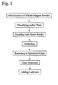
- the production steps of the compound are shown in Fig. 1.
- Preliminary blended pellets prepared in EXAMPLE 1 were used as compounds for COMPARATIVE EXAMPLE 1.
- the a/b exceeded 3.
- the number (average value) of magnet powder particles contained in one pellet was less than 10.
- the surface of the die cavity was finished to a surface roughness of finish symbol ( ⁇ ) according to JIS B 0601. the resultant molded product was heat-cured to an isotropic, resin-bonded magnet.
- the left end portions had the highest density of 6.32 g/cm 3
- two pieces in the center portion had the lowest density of 6.18-6.19 g/cm 3
- the right end portions had the second highest density of 6.30 g/cm 3 .
- the results are plotted by ⁇ in Fig. 4 (a).
- the density of isotropic, resin-bonded magnets shown by the plots ⁇ were 6.0 g/cm 3 or more and less than 6.20 g/cm 3 , indicating that the roundness of their outer surfaces was as poor as 16-26 ⁇ m.
- the left end portions had the highest density of 6.11 g/cm 3
- two pieces in the center portion had the lowest density of 5.78-5.80 g/cm 3
- the right end portions had the second highest density of 6.09 g/cm 3 .
- Each of the compounds of EXAMPLE 1 and the pellets of COMPARATIVE EXAMPLE 1 was charged into a 50-mm-diameter cavity of a compression-molding die and compressed to form a cylindrical isotropic, resin-bonded magnet having a diameter D of 50 mm and a height L of 50 mm.
- Each of the resultant molded products was heat-cured and divided to ten pieces in an L direction to measure its density distribution in an L direction. As a result, it was found that all molded products had the highest density in both ends and the lowest density in a center portion.
- difference in density between both ends and the center portion was as small as 0.25 g/cm 3 or less in the case of using the compounds of EXAMPLE 1, while it was as large as more than 0.3 g/cm 3 in the case of using the pellets of COMPARATIVE EXAMPLE 1.
- the heat-cured cylindrical isotropic, resin-bonded magnets had an outer surface roundness of less than 10 ⁇ m in the case of using the compounds of EXAMPLE 1, while they had as large an outer surface roundness as more than 15 ⁇ m in the case of using the pellets of COMPARATIVE EXAMPLE 1.
- each cylindrical isotropic, resin-bonded magnet was formed by compression molding using the same compounds as in EXAMPLE 1 in the same manner as above except for changing (D, L) to (1 mm, 0.3 mm), (10 mm, 5 mm), and (30 mm, 30 mm), respectively, and evaluated. As a result, it was found that all resin-bonded magnets had as good outer surface roundness as less than 10 ⁇ m.
- the compound of EXAMPLE 1 was charged into a cavity of a predetermined compression-molding die and compression-molded to form a ring-shaped, isotropic, resin-bonded magnet having an outer diameter of 22 mm, an inner diameter of 20 mm, and a height of 11.8-12.0 mm.
- a cavity surface of the above die was finished to surface roughness expressed by a finish symbol ( ⁇ ) according to JIS B 0601.
- ⁇ finish symbol
- 100 continuously molded products were measured as to how their height varied to evaluate the chargeability and pressure transmittability of the compounds.
- Compression molding was continuously carried out under a molding pressure of 5.4 x 10 8 Pa (5.5 ton/cm 2 ) with a mechanical press. All of the resultant molded products were within the height standard, satisfying the dimension standard even after heat curing.
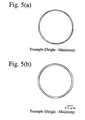
- the ring-shaped, isotropic, resin-bonded magnet of the present invention has roundness in their outer and inner surfaces that is reduced to as small as 10 ⁇ m or less. It is considered that the difference in outer surface roundness between Figs. 5 and 6 is derived from the difference in chargeability and pressure transmittability between the compounds of EXAMPLE 1 and COMPARATIVE EXAMPLE 3, which causes the spring back of compression-molded products.
- the compound of EXAMPLE 1 was charged into a cavity of a molding die in a compression-molding machine with upper and lower punches for compression, and molded under molding pressure of 5.7 x 10 8 Pa (5.8 ton/cm 2 ), to form a ring-shaped, isotropic, resin-bonded magnet having an outer diameter of 30 mm, an inner diameter of 25 mm (thickness 2.5 mm), and a height L of 30 mm.
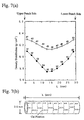
- the ring-shaped, isotropic, resin-bonded magnet was divided to 10 pieces at substantially equal length in an L direction, and each cut piece (Nos.41-50) was measured with respect to density. The results are shown by ⁇ in Fig. 7(a). It should be noted that the same No. represents the same sample in Figs. 7(a) and 7(b).
- Ring-shaped isotropic, resin-bonded magnets having an outer diameter of 30 mm, an inner diameter of 25 mm (thickness 2.5 mm), and a height L of 30 mm were molded in the same manner as in EXAMPLE 6 except for using the pellets of COMPARATIVE EXAMPLE 1.
- each resin-bonded magnet was divided to ten pieces in substantially equal length in an L direction as shown in Fig. 7(b) to measure the density of each cut piece (Nos. 51-60). The results are shown by ⁇ in Fig. 7 (a). It should be noted that the same No. represents the same sample in Figs. 7(a) and 7(b).
- the ring-shaped resin-bonded magnet of EXAMPLE 6 formed from the compound of EXAMPLE 1 had a density, which was the highest (6.30 g/cm 3 ) in an end portion (No. 41) on the side of the upper punch, the second highest (6.29 g/cm 3 ) in an end portion (No. 50) on the side of the lower punch, and the lowest (6.15-6.16 g/cm 3 ) in a center portion (Nos. 45, 46).
- the ring-shaped resin-bonded magnet of COMPARATIVE EXAMPLE 6 formed by using the pellets of COMPARATIVE EXAMPLE 1 had a density of 6.09 g/cm 3 in an end portion (No.51) on the upper punch side, and 6.08 g/cm 3 in end portion (No.60) on the lower punch side, but as low as 5.75 g/cm 3 at No. 55 and 5.77 g/cm 3 at No.56 in a center portion.
- the ring-shaped resin-bonded magnets of EXAMPLE 6 were 2.7% higher in the total magnetic flux than those of
- an average air gap between the rotor and a stator was set to 0.3 mm.
- Sm oxide powder, La oxide powder and Fe powder each having purity of 99.9% or more were formulated to a main component composition of a Sm-La-Fe mother alloy corresponding to a magnet powder composition described below.
- Metallic Ca in an amount 1.0 times a stoichiometric amount necessary for reducing Sm oxide and La oxide was added to the above formulation and then mixed.
- the resultant mixture was introduced into a reduction/diffusion reaction and heated at 1200°C for 4 hours in an Ar gas atmosphere and cooled to room temperature.
- the resultant reaction product was coarsely pulverized and sieved under 32 mesh. After washing the reaction product, water was removed by a centrifugal separator. It was then dried at room temperature in a reduced pressure atmosphere of 66.5 Pa (0.5 Torr) for 2 hours to obtain Sm-La-Fe mother alloy powder formed by a reduction/diffusion method.
- the above mother alloy powder was subjected to a hydrogenation-decomposition reaction treatment in a hydrogen gas atmosphere of 1.0 x 10 5 Pa (1atm) at 700°C for 1 hour and then a dehydrogenation-recombination reaction treatment in vacuum of about 6.7 Pa (5 x 10 -2 Torr) at 800°C for 1.5 hours. After sieving the resultant product under 200 mesh, it was nitrided by heating in a nitriding gas atmosphere of 1.0 x 10 5 Pa (1atm) at 450°C for 10 hours and cooled to room temperature. It was then heat-treated at 400°C for 30minutes in an Ar gas stream and cooled to room temperature.
- the resultant magnet powder had a main component composition represented by Sm 7.7 La 0.5 Fe bal. N 12.9 by atomic %, with an oxygen content of 0.17 weight %, a carbon content of 0.06 weight %, a Ca content of 0.03 weight %, and an average particle size of 22 ⁇ m.
- the observation of the magnet powder particles with a scanning-type electron microscope revealed that they were in the form of round particles, substantially composed of a hard magnetic phase of Th 2 Zn 17 -type crystal structure (average crystal grain size: 0.19 ⁇ m), the average area ratio of ⁇ -Fe being 0.04%.
- the preliminarily blended pellets were introduced into an extruder heated at about 220°C in an argon gas atmosphere as shown in Fig. 2 (a). Rounding was subsequently carried out in the same manner as in EXAMPLE 1 to provide round compounds.
- the resultant rounded compounds were charged into a cavity of a heated compression-molding die, to compression-mold ring-shaped, isotropic, resin-bonded magnets having an outer diameter of 22 mm, an inner diameter of 20 mm, and a height of 11.9 mm.
- the resultant molded products were measured with respect to roundness in their outer and inner surfaces. The results are shown in Table 3. It is clear from Table 3 that they had good roundness. Also, the ring-shaped resin-bonded magnets had density of 5.8 g/cm 3 , useful magnetic properties.
- Sm oxide powder, Fe powder and Al powder each having purity of 99.9% or more were formulated to a main component composition of an Sm-Fe-Al mother alloy corresponding to each magnet powder composition shown in Table 3.
- Metallic Ca in an amount 1.0 times a stoichiometric amount necessary for reducing Sm oxide was added to the above formulation.
- the resultant mixture was treated in the same manner as in EXAMPLE 7 to form nitride magnet powder having a main component composition shown in Table 3 and substantially composed of a 2-17-type hard magnetic phase.
- the 2-17-type hard magnetic phase in the nitride magnet powder of EXAMPLE 8 had an average crystal grain size of 0.18 ⁇ m, with an average area ratio of ⁇ -Fe of 0.02% and an average particle size of 24 ⁇ m.
- the 2-17-type hard magnetic phase in the nitride magnet powder of EXAMPLE 9 had an average crystal grain size of 0.19 ⁇ m, with an average area ratio of ⁇ -Fe of 0.03% and an average particle size of 23 ⁇ m.
- the heat-treated mother alloy was pulverized to an average particle size of about 100 ⁇ m. Next, it was nitrided by heating at 450°C in a nitriding gas of 1 atm for 20 hours and cooled to room temperature, to obtained isotropic nitride magnet powder.
- This magnet powder had a main component composition represented by Sm 5.3 La 0.7 Fe bal. Co 5.0 Zr 3.5 N 14.7 by atomic %.
- the observation by X-ray diffraction (Cu-K ⁇ ) and transmission-type electron microscope revealed that the magnet powder was composed of a TbCu 7 -type nitride magnet phase and ⁇ -Fe.
- the TbCu 7 -type nitride magnet phase of this magnet powder had an average crystal grain size of 55 nm with an average area ratio of 86.9%.
- ⁇ -Fe had an average crystal grain size of 23 nm with an average area ratio of 13. 1%.
- a blend of 97.5 parts by weight of nitride magnet powder in EXAMPLE 10 and 2.5 parts by weight of a liquid epoxy resin was introduced into a heating, pressurizing-type kneader, in which it was preliminarily blended and granulated to provide pellets.
- the pellets were compression-molded and heat-cured in the same manner as in EXAMPLE 10 to form ring-shaped, isotropic, resin-bonded magnets having an outer diameter of 22 mm, an inner diameter of 20 mm, and a height of 11.9 mm.
- the resultant ring-shaped, isotropic, resin-bonded magnets were measured with respect to roundness in their outer and inner surfaces. The results are shown in Table 4.
- EXAMPLE 10 The total magnetic flux measured in the same manner as in EXAMPLE 10 was 1.5% less than that in EXAMPLE 10.
- No. Formulation of Magnet Powder (atomic %) Roundness ( ⁇ m) Outer Surface Inner Surface EX. 10 Sm 5.3 La 0.7 Fe bal. Co 5.0 Zr 3.5 N 14.7 6-9 5-9 REF.
- EX. 1 >15 >15
- EX. 11 Sm 8.0 La 0.7 Fe bal. Ti 2.0 B 1.0 N 12.0 (50 parts by weight) + Nd 12.8 Fe bal. B 6.5 Nb 1.5 (50 parts by weight) 6-9 5-9 REF.
- EX. 2 > 15 > 15
- EX. 12 Sm 5.3 La 0.7 Fe bal. Co 5.0 Zr 3.5 N 14.7 (50 parts by weight) + Nd 12.8 Fe bal. B 6.5 Nb 1.5 (50 parts by weight) 6-9 6-9 REF.
- EX. 3 > 15 > 15 > 15
- each of the ring-shaped, isotropic, resin-bonded magnets of EXAMPLE 10 and REFERENCE EXAMPLE 1 was provided with four magnetic poles symmetrically on the outer surface to constitute a rotor, which was then assembled in a brushless DC motor. With an average air gap set to 0.28 mm between the rotor and the stator in this brushless DC motor, the maximum efficiency was measured. As a result, it was found that the brushless DC motor comprising the ring-shaped, isotropic, resin-bonded magnet of EXAMPLE 10 had the maximum efficiency 0.8% higher than that of the brushless DC motor comprising the ring-shaped, isotropic, resin-bonded magnet of REFERENCE EXAMPLE 1.
- Strip casting was carried out in the same manner as in EXAMPLE 1 except for changing to mother alloy melt compositions corresponding to the nitride magnet powder shown in Table 4, and nitride magnet powder shown in Table 4 was produced in subsequently in the same manner as in EXAMPLE 1.
- This magnet powder had a main component composition of Sm 8.0 La 0.7 Fe bal. Ti 2.0 B 1.0 N 12.0 by atomic %, and an average particle size of 33 ⁇ m, which was substantially composed of a hard magnetic phase having a Th 2 Zn 17 -type crystal structure having an average crystal grain size of 0.20 ⁇ m, an average area ratio of ⁇ -Fe being 0.01%.
- a blend of the mixed magnet powder prepared in EXAMPLE 11 and a liquid epoxy resin was charged into a heating, pressurizing-type kneader, in which it was preliminarily blended and granulated to form pellets.
- the resultant pellets were then compression-molded and heat-cured in the same manner as in EXAMPLE 11 to form ring-shaped, isotropic, resin-bonded magnets having an outer diameter of 22 mm, an inner diameter of 20 mm, and a height of 11.9 mm.
- the resultant ring-shaped, isotropic, resin-bonded magnets were measured with respect to roundness in their outer and inner surfaces. The results are shown in Table 4. Also, as a result of measurement carried out in the same manner as in EXAMPLE 11, the total magnetic flux of this REFERENCE EXAMPLE was 2.0% lower than that of EXAMPLE 11.
- EXAMPLE 10 50 parts by weight of nitride magnet powder (Sm 5.3 La 0.7 Fe bal. Co 5.0 Zr 3.5 N 14.7 ) of EXAMPLE 10 was mixed with 50 parts by weight of Nd-Fe-B magnet powder (Nd 12.8 Fe bal. B 6.5 Nb 1.5 ) of EXAMPLE 11. With 97.5 parts by weight of the resultant mixed magnet powder formulated with 2.5 parts by weight of a liquid epoxy resin, rounded compounds were then produced in the same manner as in EXAMPLE 1. The rounded compounds were compression-molded and heat-cured in the same manner as in EXAMPLE 4 to produce ring-shaped, isotropic, resin-bonded magnets having an outer diameter of 22mm, an inner diameter of 20 mm, and a height of 11.9 mm.
- a blend of the mixed magnet powder prepared in EXAMPLE 12 and a liquid epoxy resin was charged into a heating, pressurizing-type kneader, in which it was preliminarily blended and granulated to form pellets.
- the resultant pellets were then compression-molded and heat-cured in the same manner as in EXAMPLE 12 to form ring-shaped, isotropic, resin-bonded magnets having an outer diameter of 22 mm, an inner diameter of 20 mm, and a height of 11.9 mm.
- the resultant ring-shaped, isotropic, resin-bonded magnets were measured with respect to roundness in their outer and inner surfaces. The results are shown in Table 4. Also, as a result of measurement carried out in the same manner as in EXAMPLE 12, the total magnetic flux of this REFERENCE EXAMPLE was 1.7% lower than that of EXAMPLE 12.
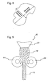
- the rounded compounds of EXAMPLE 1 were charged into a compound-conveying apparatus 60 of Fig. 9 heated at about 90°C, and a softened compound 62 discharged from an exit 61 of the compound-conveying apparatus 60 was supplied between rolls 64, 64 heated at 50°C in the air, so that it was rolled to two sheet-shaped, molded products 70 having a thickness of 2.0 mm and 3.0 mm respectively and a width of about 100 mm. Each sheet-shaped, molded product 70 was cut to a predetermined length, and heat-cured at 150°C for 1 hour in the air.
- the measurement of surface roughness (maximum roughness R max according to JIS B 0601) of the resultant sheet-shaped, resin-bonded magnets revealed that R max was 2-5 ⁇ m, indicating extremely flat surface.
- Sheet-shaped resin-bonded magnets were produced in the same manner as in EXAMPLE 13 except for adjusting a gap between the rolls 64, 64 to provide the sheet-shaped, resin-bonded magnets with thickness of 0.1 mm, 1.0 mm, and 5.0 mm, respectively.
- the resultant sheet-shaped, resin-bonded magnets had R max within a range of 3-8 ⁇ m, indicating extremely flat surface.
- Sheet-shaped resin-bonded magnets were produced in the same manner as in EXAMPLE 13 except for using the pellets of COMPARATIVE EXAMPLE 1. However, the resultant sheet-shaped, resin-bonded magnets had R max of more than 15 ⁇ m, poor surface conditions.
- Sheet-shaped resin-bonded magnets were produced in the same manner as in EXAMPLE 13 except for using the rounded compounds of EXAMPLE 10, and their R max was measured. Their R max was 4-9 ⁇ m.
- Sheet-shaped resin-bonded magnets were produced in the same manner as in EXAMPLE 15 except for using the pellets of REFERENCE EXAMPLE 1, and their R max was measured. Their R max was more than 15 ⁇ m, poorer in surface conditions than EXAMPLE 15.
- Sheet-shaped resin-bonded magnets were produced in the same manner as in EXAMPLE 13 except for using the rounded compounds of EXAMPLE 11, and their R max was measured. Their R max was 5-9 ⁇ m.
- Sheet-shaped resin-bonded magnets were produced in the same manner as in EXAMPLE 16 except for using the pellets of REFERENCE EXAMPLE 2, and their R max was measured. Their R max was more than 15 ⁇ m, poorer in surface conditions than EXAMPLE 16.
- Sheet-shaped resin-bonded magnets were produced in the same manner as in EXAMPLE 13 except for using the rounded compounds of EXAMPLE 12, and their R max was measured. Their R max was 5-9 ⁇ m.
- Sheet-shaped resin-bonded magnets were produced in the same manner as in EXAMPLE 17 except for using the pellets of REFERENCE EXAMPLE 3, and their R max was measured. Their R max was more than 15 ⁇ m, poorer in surface conditions than EXAMPLE 17.
- a mother alloy melt adjusted to have a composition corresponding to the following nitride magnet powder was poured onto a surface of a cooling copper alloy roll (diameter: 300 mm) of a twin-roll strip caster rotating at a peripheral speed of 0.5 m/second to rapidly quench the melt to form a thin mother alloy ribbon.
- the resultant thin mother alloy ribbon was subjected to a hydrogenation-decomposition reaction treatment at 675°C for 1 hour in a hydrogen gas atmosphere of 1.0 x 10 5 Pa (1atm), and then to a dehydrogenation-recombination reaction treatment at 790°C for 1.5 hours in vacuum of 4.0-8.0 Pa (3-6 x 10 -2 Torr).
- the thin mother alloy ribbon was pulverized by a jaw crusher and a disc mill in an argon gas atmosphere and then sieved to a particle size smaller than 200 mesh.
- the resultant mother alloy powder was nitrided at 440°C for 10 hours in a nitriding gas atmosphere of 1.0 x 10 5 Pa (1atm) and then cooled to room temperature. It was then heat-treated at 400°C for 30 minutes in an argon gas stream and cooled to room temperature, to form nitride magnet powder having a main component composition of Sm 9.2 La 0.05 Fe bal Ti 2.7 B 1.0 N 12.7 and having an average particle size of 20 ⁇ m, which was substantially composed of a hard magnetic phase having a Th 2 Zn 17 -type crystal structure having an average crystal grain size of 0.18 ⁇ m. In this magnet powder, an average area ratio of ⁇ -Fe was 0.01%.
- the sheet-shaped, molded products were heated at 50°C for 10 hours in the air, subjected to a curing treatment at 150°C for 2 hours in the air, and then cooled to room temperature.
- the resultant sheet-shaped, isotropic, resin-bonded magnets were magnetized at a magnetizing field intensity of 1.9 MA/m (25 kOe) at room temperature (25°C).
- the resultant sheet-shaped, isotropic, resin-bonded magnets had (BH) max of 28.7 kJ/m 3 (3.6 MGOe).
- Fig. 12 (a) shows a scanning-type electron photomicrograph of this magnet powder. It is clear from Fig. 12 (a) that it was in the form of round particles.
- (BH) max was 31.8 kJ/m 3 (4.0 MGOe), and iHc was 748.1 kA/m (9.4 kOe). Also, they had a density of 5.4 g/cm 3 .
- Fig. 10 shows the change of (BH) max of the above sheet-shaped, resin-bonded magnet when a magnetizing field intensity was changed at room temperature (25°C).
- Irreversible loss of flux [( ⁇ 2 ⁇ 1 ) / ⁇ 1 ] x 100 (%)
- Fig. 14 is a cross-sectional view showing an important portion of a typical developing roll apparatus 80 in which the magnet roll of the present invention was assembled
- Fig. 15 is a cross-sectional view taken along the line A-A in Fig. 14.
- the developing roll apparatus 80 comprises a magnet roll 81, a cylindrical sleeve 82 containing a magnet roll 81, a pair of flanges 83a, 83b attached to both ends of the cylindrical sleeve 82, and bearings 84a, 84b mounted onto inner surfaces of the flanges 83a, 83b, the shaft 86 being rotatably supported by the bearings 84a, 84b.
- a magnet roll 81 comprises a radially anisotropic ferrite resin-bonded magnet 88 having an outer diameter D of 20.0 mm and a length of 220.0 mm provided with a groove 87 extending in an axial direction, a magnet 89 for a developing magnetic pole N 1 , which was cut from the above sheet-shaped, resin-bonded magnet to a thickness of 3.0 mm, a width of 3.0 mm and a length of 220.0 mm and fixed to the groove 87, and a ferromagnetic shaft 86 (made of S45C) inserted into the inner diameter side of the radially anisotropic ferrite resin-bonded magnet 88.
- One flange 83b is provided with a seal member (oil seal) 85 on an end surface.
- seal member oil seal
- Four magnetic poles in total extending in an axial direction were provided on an outer surface of the magnet roll 81.
- the non-magnetic sleeve 82 and the flanges 83a, 83b are made of an aluminum alloy.
- a magnetic developer is absorbed onto an outer surface of the sleeve 82, and conveyed to a developing region in which the sleeve 82 opposes an image-bearing member (not shown), to develop electrostatic image on the image-bearing member.
- a closed magnetic circuit 90 is formed in the magnet roll 81 as shown by the dotted line in Fig. 15, a strong magnetic field is generated on the sleeve 82.
- a reference numeral 95 denotes a magnetic gap.
- a surface magnetic flux density Bo was measured in a range of 100 mm in an axial direction on an outer surface including an N 1 magnetic pole near an axial center portion of the magnet roll 81.
- Bo was as high as 0.18 T (1800 G) in average value, with as good unevenness dBo of Bo as less than 0.005 T (50 G).
- the developing roll apparatus 80 was assembled in a copier to make 10,000 copies, and the appearance of the sheet-shaped, resin-bonded magnet 89 constituting the magnet roll 81 was examined. As a result, it was confirmed that the sheet-shaped, resin-bonded magnet 89 kept good appearance without deterioration in a magnetic force.
- Nitride magnet powder having a main component composition shown in Table 5 (average particle size: about 20 ⁇ m) was produced in the same manner as in EXAMPLE 18 except for changing the main component composition, and by using the above nitride magnet powder, a sheet-shaped, isotropic, resin-bonded magnet was produced to measure its magnetic properties. The measurement results are shown in Table 5.
- the sheet-shaped, resin-bonded magnet had a density of 5.4-5.5 g/cm 3 .
- Each magnet powder was substantially composed of a hard magnetic phase of a Th 2 Zn 17 -type crystal structure having an average crystal grain size of about 0.2 ⁇ m, an average area ratio of ⁇ -Fe being 0.01-0.03%.
- nitride magnet powder having a main component composition represented by Sm 9.2 Fe bal. Ti 2.7 B 1.0 N 12.8 and having an average particle size of 22 ⁇ m, which was substantially composed of a hard magnetic phase (average crystal grain size: 0.20 ⁇ m) having a Th 2 Zn 17 -type crystal structure, and magnetized at room temperature (25°C) and a magnetizing field intensity of 1.9 MA/m (25kOe). As a result, they had (BH) max of 25.4 kJ/m 3 (3.2 MGOe).
- Fig. 10 shows (BH) max of the sheet-shaped, resin-bonded magnet when a magnetizing field intensity was changed at room temperature (25°C) in the same manner as in EXAMPLE 19, and Fig. 11 shows the irreversible loss of flux of the sheet-shaped, resin-bonded magnet.
- Nitride magnet powder having a main component composition shown in Table 5 and an average particle size of about 20 ⁇ m was produced in the same manner as in EXAMPLE 18 except for using the La content of 3.0 atomic %, and a sheet-shaped, resin-bonded magnet was formed therefrom to measure its magnetic properties. The measurement results are shown in Table 5.
- Fig. 10 shows (BH) max of the sheet-shaped, resin-bonded magnet when a magnetizing field intensity was changed at room temperature (25°C) in the same manner as in EXAMPLE 19, and Fig. 11 shows the irreversible loss of flux of the sheet-shaped, resin-bonded magnet.
- No. Composition of Nitride Magnet Powder (atomic %) (BH) max (kJ/m 3 ) (MGOe) iHc (kA/m) (kOe) EX. 18 Sm 9.2 La 0.05 Fe bal. Ti 2.7 B 1.0 N 12.7 28.7 771.9 3.6 9.7 EX. 19 Sm 8.5 La 0.7 Fe bal. Ti 2.7 B 1.0 N 12.5 31.8 748.1 4.0 9.4 EX.
- EXAMPLES 21, 22, 24 and 26 rounded compounds were produced in the same manner as in EXAMPLE 1 except for using each magnet powder shown in Table 6, and rolled to each 2.6-mm-thick, sheet-shaped, resin-bonded magnet in the same manner as in EXAMPLE 13.
- Each of the resultant sheet-shaped, resin-bonded magnet was cut to a thickness of 2.6 mm, a width of 3.0 mm, and a length of 220.0 mm, and assembled in a magnet roll shown in Fig. 15 in place of the sheet-shaped, resin-bonded magnet 89 constituting a developing magnetic pole N 1 of the magnet roll 81.
- a surface magnetic flux density Bo was measured in a range of 100 mm in an axial direction on an outer surface including an N 1 magnetic pole near an axial center portion of the magnet roll. Bo measured (average value) are shown in Table 6.
- a magnet roll 119 having a different structure according to the present invention shown in Fig. 16 (a) can be produced, for instance, as follows: First, after forming an axially extending groove 113 in a developing magnetic pole portion of a cylindrical, isotropic, ferrite sintered magnet 117 fixed to a shaft 118, the sheet-shaped, isotropic, resin-bonded magnet 116 of the present invention having a substantially U-shaped cross section was fixed to the groove 113. Because the sheet-shaped, resin-bonded magnet 116 is provided with a recess 114 in an axial direction, a magnetic flux density distribution in a gap immediately above the developing magnetic pole (N 1 ) has a waveform having 2 peaks.
- a magnet roll 124 having a different structure according to the present invention shown in Fig. 16 (b) can be produced, for instance, as follows: First, a softened compound based on ferrite magnet powder for resin-bonded magnets and a thermoplastic resin is charged into an extrusion die cavity to which a radially orienting magnetic field is applied, extruded and then solidified. After demagnetization, it is cut to a predetermined length to form a C-shaped, molded product 120 having a gap 122. After the molded product 120 is fixed to a shaft 123, the sheet-shaped, isotropic, resin-bonded magnet 121 of the present invention is fixed in a gap 122.
- the C-shaped, molded product 120 may be ferrite resin-bonded magnet or ferrite sintered magnet having isotropy or radial anisotropy.
- a magnet roll 129 having a different structure according to the present invention shown in Fig. 16 (c) can be produced, for instance, as follows:
- the sheet-shaped, resin-bonded magnet 126 of the present invention is wound around a shaft 128 by at least one turn and fixed to the shaft 128.
- 127 denotes a seam of the sheet-shaped, resin-bonded magnet 126.
- a composite magnet roll 130 having a different structure according to the present invention shown in Fig. 17 is constituted by a ring-shaped outer layer 131 composed of the sheet-shaped, isotropic, resin-bonded magnet of the present invention, a inner layer 132 composed of a ring-shaped ferrite resin-bonded magnet provided with multi-magnetic pole anisotropy (symmetric six-magnetic pole anisotropy), and a shaft 133 fixed to the inside of an inner layer 132.
- 131a denotes a seam of sheet-shaped, resin-bonded magnet.
- the magnet roll When the magnet roll is entirely constituted by an integral ferrite resin-bonded magnet having multi-magnetic pole anisotropy, a magnetizing wave form is constrained in an anisotropy-giving direction, resulting in large unevenness dBo of Bo in an axial direction. Because the sheet-shaped, R-T-N isotropic, resin-bonded magnet 131 constitutes an outer layer in the magnet roll 130 of the present invention, a magnetizing wave form can freely be adjusted to obtain an effect that Bo has a high average value with low dBo.
- a ratio (t 131 /t 132 ) of the thickness t 131 of the outer layer 131 to the thickness t 132 of the inner layer 132 is preferably in a range of 1:9-3:7.
- This composite magnet roll may effectively be used not only for small-diameter products of 10-20 mm in outer diameter, but also for large-diameter products of 50-60 mm in outer diameter.
- a composite magnet roll 140 having a different structure according to the present invention shown in Fig. 18 is constituted by an inner layer 141 of the sheet-shaped, isotropic, resin-bonded magnet of the present invention wound around and adhered to a shaft 144, and an outer layer 142 of a ring-shaped ferrite resin-bonded magnet adhered to the outer surface of the inner layer 141, the ring-shaped ferrite resin-bonded magnet comprising ferrite magnet powder and a thermoplastic resin and being provided with multi-magnetic pole anisotropy (symmetric 12-magnetic pole anisotropy).
- the magnet roll 140 When the magnet roll 140 is entirely formed by a ferrite resin-bonded magnet provided with multi-magnetic pole anisotropy, more multi-magnetic pole anisotropy tends to be given to a thin surface layer as the number of magnetic poles increases, resulting in decrease in Bo.
- the magnetic pole interval P 2 and the thickness t 142 of the outer layer 142 meet the condition of P 2 /t 142 ⁇ 1.6, multi-magnetic pole anisotropy is given to the entire outer layer 142, resulting in improved Bo in the magnet roll 140.
- a ratio (t 141 /t 142 ) of the thickness t 141 of the inner layer 141 to the thickness t 142 of the outer layer 142 is preferably in a range of 4:1-3:2.
- This composite magnet roll is effectively used not only as a small-diameter product having an outer diameter of 10-20 mm but also as a large-diameter products having an outer diameter of 50-60 mm.
- a magnet roll 170 having a different structure according to the present invention shown in Fig. 19 (a) is constituted by attaching the sheet-shaped, isotropic, resin-bonded magnet 172 of the present invention to a large-diameter portion 171a of a ferromagnetic shaft.
- the sheet-shaped, resin-bonded magnet 172 has a seam 174 at an angle ⁇ (0° ⁇ ⁇ 90°) relative to an axial direction X2, with a magnetic pole boundary 175 and the seam 174 in parallel.
- it is suitable for a developing roll apparatus in which a magnet roll is rotated.
- a magnet roll 180 having a different structure according to the present invention shown in Fig. 19 (b) is constituted by attaching the sheet-shaped, isotropic, resin-bonded magnet 182 of the present invention to a large-diameter portion 181a of a ferromagnetic shaft.
- the sheet-shaped, resin-bonded magnet 182 is provided with a gap 185 at a position corresponding to a seam, and the gap 185 is at an angle ⁇ (0° ⁇ ⁇ 90°) relative to an axial direction X3. Also, the gap 185 is in parallel with the magnetic pole boundary 188. Though not particularly restrictive, this is suitable for a developing roll apparatus in which a magnet roll is rotated.
- the magnet roll of the present invention preferably has 3-32 magnetic poles, more preferably 4-16 magnetic poles at an equal or unequal interval on an outer surface in a circumferential direction.
- the magnet roll of the present invention is highly useful for practical applications, when a ratio L/D of the length L to the outer diameter D is 5 or more.
- the outer diameter D is preferably 2-60 mm, more preferably 5-30 mm, particularly preferably 10-20 mm.
- the length L is preferably 50-350 mm, more preferably 100-350 mm, particularly preferably 200-350 mm.
- Fig. 20 (a) is a front view showing an important portion of one example of the fan motor of the present invention
- Fig. 20 (b) is a view showing the fan motor seen from back.
- the fan motor 210 of the present invention is provided with a rotor 207 and a stator (armature) 208 opposing via an air gap 209.
- 201 denotes a ring-shaped field magnet having an outer diameter of 30.0 mm and a height of 30.0 mm, which is formed by winding the above 2.0-mm-thick, sheet-shaped, isotropic, resin-bonded magnet by one turn, and fixed to an inner surface of a ring-shaped, ferromagnetic yoke 202 (made of SS400), and magnetized to have four magnetic poles symmetrically.
- 201a denotes a seam of the sheet-shaped, resin-bonded magnet.
- the fan motor 210 has a shaft 203 (rotor 207) rotatable at a predetermined speed via bearings 206.
- the rotatable shaft 203 is disposed coaxially with the yoke 202, and integrally held by an injection-molded member 204 made of a glass-reinforced polybutylene terephthalate resin.
- the support member 204 comprises a fan 204a, a rim 204b, a spoke 204c and a rear member 204d, to provide the rotor 207 with practically useful strength.
- Magnetization is carried out in the form of a rotor 207.
- the outer surface of stator 208 is provided with stator magnetic poles (four symmetric magnetic poles), which are not shown.
- the fan 204a is rotated efficiently by a rectangular wave-conducting signal (180° conducting at electrical angle) supplied from a fan motor-driving control circuit (not shown).
- a surface magnetic flux density (Bo) distribution was measured on an inner surface of the field magnet 201 in a circumferential direction. The results are shown in Fig. 21. The maximum value of Bo at four magnetic poles was 0.16 T (1600 G) on average.
- the fan motor 210 comprising the rotor 207 was assembled in an air-blowing fan to carry out continuous operation for one month. After continuous operation, the field magnet201 was free from cracking, showing good appearance. Also, the continuous operation did not cause any deterioration in the performance of the fan motor 210.
- a fan motor was produced in the same manner as in EXAMPLE 32 except for using a radially anisotropic, ring-shaped, ferrite resin-bonded magnet (tradename KPM-2A, outer diameter: 30.0 mm, inner diameter: 26.0 mm, and height: 30.0 mm) available from Hitachi Metals, Ltd. as a field magnet with four symmetric magnetic poles.
- a surface magnetic flux density distribution was measured on an inner surface of the ring-shaped, resin-bonded, ferrite magnet disposed in this fan motor rotor in a circumferential direction. The results are shown in Fig. 21.
- the averaged maximum value of Bo at four magnetic poles was less than that of EXAMPLE 32.
- a 2.0-mm-thick sheet-shaped, isotropic, resin-bonded magnet was produced, using the pellets of COMPARATIVE EXAMPLE 1.
- This sheet-shaped, isotropic, resin-bonded magnet was assembled in a rotor as a field magnet for a fan motor.
- a surface magnetic flux density distribution was measured on an inner surface of the sheet-shaped, resin-bonded magnet disposed in this fan motor rotor in a circumferential direction. The results are shown in Fig. 21.
- the averaged maximum value of Bo at four magnetic poles was less than that of EXAMPLE 32 and more than that of COMPARATIVE EXAMPLE 12.
- the thickness of the sheet-shaped, resin-bonded magnet and an inner surface of a yoke 202 to which a field magnet 201 formed by winding the sheet-shaped, resin-bonded magnet is fixed were relatively changed to examine whether or not the sheet-shaped, resin-bonded magnet fixed to the yoke 202 is cracked.
- the sheet-shaped, molded product of 0.05-5.0 mm in thickness and 100 mm in width was produced in the same manner as in EXAMPLE 19 except for changing the thickness of the sheet-shaped, molded product.
- the sheet-shaped, molded product was cut to predetermined width and length and subjected to a heat treatment and a curing treatment.
- the resultant sheet-shaped, molded product had a density of 5.4-5.5 g/cm 3 .
- Cut products of each thickness were wound in a ring shape by one turn, and each of them was adhered to an inner surface of a ring-shaped, ferromagnetic yoke of 1.0-100.0 mm in inner diameter, to prepare 20 samples for each sheet thickness and each yoke inner diameter shown in Table 7.
- Each sample was left to stand at room temperature in the air for one month to examine how it was cracked.
- the results are shown in Table 7.
- the inner diameter of the yoke shown in Table 7 substantially corresponds to the outer diameter of the ring-shaped field magnet. It is clear from Table 7 that the thicker the sheet-shaped, isotropic, resin-bonded magnet, and the smaller the yoke inner diameter, the more likely cracking takes place.
- a sheet-shaped, molded product having a thickness of 0.05-5.0 mm and a width of about 100 mm was produced in the same manner as in EXAMPLE 33 except for using the nitride magnet powder of EXAMPLE 10. it was cut to a predetermined width and length, and subjected to a heat treatment and a curing treatment. Each of the sheet-shaped, molded product was adhered to an inner surface of a yoke in the same manner as in EXAMPLE 33 except for winding a cut product of each thickness by one turn. The resultant samples were examined as to whether or not the sheet-shaped, resin-bonded magnets were cracked. The results are shown in Table 8. It is clear from Table 8 that there was cracking in any combination of sheet thickness and yoke inner diameter.
- Rounded compounds were produced by blending 93.5 parts by weight of the nitride magnet powder of EXAMPLE 19 with 6.5 parts by weight of a liquid epoxy resin, and subsequently in the same manner as in EXAMPLE 1.
- the field magnet was provided with four magnetic poles symmetrically.
- the measurement of a surface magnetic flux density (Bo) distribution on an inner surface in an axial center portion of each field magnet in a circumferential direction revealed that the maximum value of Bo at four magnetic poles was 0.167 T (1670 G) on average, higher than that of EXAMPLE 32.
- FIGs. 22 (a)-(d) shows a seam of the wound sheet-shaped, resin-bonded magnet and a magnetic pole along the seam, when a field magnet is formed by winding the sheet-shaped, isotropic, resin-bonded magnet of the present invention.
- Fig. 22 (a) shows an example in which a seam 331 (magnetic pole boundary) of a ring-shaped field magnet 330 is in parallel with the axial direction of the field magnet 330.
- Fig. 22 (b) shows an example in which a seam (magnetic pole boundary) 341 of a ring-shaped field magnet340 is at an angle 0 (0° ⁇ 90°) relative to the axial direction X4 of a field magnet 340, with four magnetic poles in parallel to the seam 341. This structure is effective to reduce a cogging torque.
- Fig. 22 (c) shows an example in which a seam (magnetic pole boundary) 351 of a ring-shaped field magnet 350 has a portion 351a at an angle ⁇ (0° ⁇ 90°) relative to an axial direction X5 and a portion 351b in perpendicular to the axial direction X5, with four magnetic poles along the seam 351.
- This structure effectively suppresses a cogging torque, thereby improving the output of a rotor.
- Fig. 22 (d) shows an example in which a gap 361 is provided in a portion corresponding to the seam of the ring-shaped field magnet 360.
- the sheet-shaped, resin-bonded magnet 362 fixed to the yoke is effectively resistant to cracking by thermal stress.
- Fig. 23 shows another structure of a rotor used in the present invention.
- Fig. 23 (a) shows an outer rotor-type rotor 370 comprising the sheet-shaped, resin-bonded magnet 371 of the present invention adhered to the inner surface of a ferromagnetic yoke 372 via equal-interval gap 373.
- Fig. 23 (b) shows an inner rotor-type rotor 380 comprising a field magnet 381 formed from a one-turn winding of the sheet-shaped, resin-bonded magnet of the present invention adhered to a ferromagnetic rotor core.
- Fig. 23 (c) shows an inner rotor-type rotor 390 comprising the sheet-shaped, resin-bonded magnet 391 of the present invention adhered to an outer surface of a ferromagnetic rotor core 392 via equal-interval gap 393.
- Fig. 24 is a cross-sectional view showing an important part of a motor as vibration motor 420 for a pager according to an embodiment of the present invention.
- Fig. 24(b) is a cross-sectional view taken along the line B-B in Fig. 24(a).
- a field magnet 424 is formed by cutting a 0.5-mm- thick sheet-shaped, isotropic, resin-bonded magnet prepared in EXAMPLE 33 to predetermined width and length, and winding the cut sheet magnet by one turn and fixing it to a surface a ferromagnetic (S45C) rotor yoke 426.
- 424a denotes a seam of the sheet-shaped, resin-bonded magnet.
- the field magnet 424 is provided with four magnetic poles symmetrically on an outer surface in circumferential direction.
- An air gap 427 is adjusted to have an average thickness of 0.1 mm.
- a stator 435 has a stator core 422 and a winding 430.
- the stator core has six teeth 422a, each tooth 422a has a winding of 36 turns, and a winding 430 is constituted by a wire having a diameter of 0.10 mm.
- a substantially half-cylindrical eccentric weight 433 is attached to a tip end portion of the rotatable shaft 428, such that the eccentric weight 433 rotates integrally with the rotatable shaft 428. When the motor 420 is driven, the eccentric weight 433 rotates eccentrically, generating remarkable vibration in the motor 420.
- the motor 420 is efficiently rotated by rotation control by three-phase alternating current conduction. Lest that the field magnet 424 is demagnetized by a reverse magnetic field applied from the winding 430 on the side of the stator 435, the field magnet 424 preferably has an average permeance coefficient Pc of 0.5-3 (thickness: 0.1-0.9 mm).
- the vibration motor 420 having the above structure for a pager is extremely small, such that the outer diameter of the rotor 425 is as small as 2.0 mm, and the outer diameter of a stator 435 is as small as 6.0 mm.
- Fig. 25 shows a torque in a stationary state when current of 0.08A is supplied to a U-W phase of a winding 430 of a motor 420.
- the axis of abscissas represents a machine angle
- the axis of ordinates represents a torque.
- the maximum torque is almost 0.1 Nmm in absolute value, meaning that it can provide useful motor performance.
- the motor 420 was assembled in a cell phone, and after use for one month, it was disassembled to examine the conditions of a field magnet 424. As a result, it was found that the field magnet 424 was free from cracking, keeping motor performance useful for practical applications.
- Fig. 26 (a) is a cross-sectional view showing an important portion of a typical spindle motor 450 of the present invention
- Fig. 26 (b) is a cross-sectional view taken along the line C-C in Fig. 26 (a).
- the motor 450 comprises an air gap 447, and a stator 445 and a rotor 455 opposing each other via the air gap 447.
- the stator 445 comprises a center shaft 448, a ferromagnetic stator core 445 disposed around the center shaft 448, a core 443 and a winding 449.
- the rotor 455 comprises a field magnet 453 formed by cutting the sheet-shaped, resin-bonded magnet (thickness: 1.0 mm) prepared in EXAMPLE 33 to a predetermined width and length, winding the cut sheet-shaped, resin-bonded magnet by one turn and fixing it to an inner surface of a ferromagnetic rotor yoke 452.
- the motor 450 is a so-called outer rotating-type brushless motor in which the rotor 455 is disposed outside.
- the field magnet 453 had an extremely small inner diameter of 20 mm.
- the hard disc drive was disassembled to examine the conditions of the field magnet 453. As a result, no cracking was appreciated, indicating that it kept a motor performance useful in practical applications.
- a brush motor converted from a spindle motor having the same magnetic circuit as in Fig. 26 and provided with a brush, with a current-passing portion of a winding 449 changed such that a stator is disposed outside and an inner winding is rotatable.
- the isotropic, sheet-shaped, resin-bonded magnet of the present invention was used to produce a motor 520 having an axial air gap as shown in Fig. 27, and evaluated.
- Fig. 27 (a) is a view showing the motor 520 seen from above
- Fig. 27 (b) is a cross-sectional view taken along the line D-D in Fig. 27 (a).
- the field magnet 501 was formed by cutting a 0.5-mm-thick, sheet-shaped, isotropic, resin-bonded magnet prepared in EXAMPLE 33 in a doughnut shape, and fixing the cut sheet to a ferromagnetic back yoke 502 (S45C, etc.).
- the rotor 505 was constituted by disposing these field magnets 501 around a rotatable shaft 503.
- 12 magnetic poles were provided in these field magnets 501 in a plane at an equal interval along a rotational direction of a portion of the field magnet 501 opposing to the air gap 515.
- the stator core has 18 teeth 517a.
- the motor 520 is efficiently rotated by rotation control by a three-phase alternating current supply system.
- the field magnet 501 preferably has an average permeance coefficient Pc of 0.5-3.
- the back yoke 502 constituting the rotor 505 of the motor 520 is as thin as 0.55 mm in an axial direction, there is only extremely small core loss in the back yoke 502 because the back yoke 502 is made of a ferromagnetic material (S45C).
- the core (yoke) 517 of the stator 510 is made of silicon steel (JIS50A350) and as thin as 0.55 mm. Teeth 517a of the stator core had a winding of 72 turns, and a winding 516 was constituted by a wire having a diameter of 0.15 mm. An axial air gap 515 was as thin as 0.2 mm on average. As a result, the total thickness t 520 of the back yoke 502, the field magnet 501, the air gap 515 and the stator core 517 was 1.8 mm, providing a thin motor that was conventionally impossible. When current of 0.1 A was supplied to a U-W phase of the winding 516 of the motor 520, a torque in a stationary state was measured.
- Fig. 28 The results are shown in Fig. 28.
- the axis of abscissas represents a mechanical angle
- the axis of ordinates represents a torque.
- the maximum torque was 12 Nmm in absolute value, indicating that it had useful motor performance.
- the field magnet 501 was examined with respect to cracking. As a result, the field magnet 501 was free from cracking, without deterioration in a magnetic force.
- the compounds of EXAMPLES 10-12 were used to produce doughnut-shaped, isotropic, resin-bonded sheet magnets (thickness: 0.5 mm) as in EXAMPLE 38.
- a motor having an axial air gap was produced in the same manner as in EXAMPLE 38 except for using each of these sheet-shaped, resin-bonded magnets, and evaluated.
- the field magnets were formed from the compounds of EXAMPLES 11 and 12
- the highest motor performance was achieved, without cracking in the field magnets.
- substantially the same motor performance as in EXAMPLE 38 was achieved, without cracking in the field magnets.
- the field magnet of the rotor may have preferably 2-100, more preferably 4-16, magnetic poles with equal or different intervals.
- the sheet-shaped, resin-bonded magnet is disposed in a rotor in the above EXAMPLES, the sheet-shaped, resin-bonded magnet may be disposed on the side of a stator to constitute a motor.
- resin-bonded magnet of the present invention with increased cracking resistance, moldability and oxidation resistance, surface modifiers (silane coupling agents, etc.), lubricants, fillers and antioxidants may be added in a total amount of 2 weight % or less.
- the isotropic, resin-bonded magnet of the present invention preferably has a corrosion-resistant coating (epoxy resin coating, etc.) in an average thickness of 0.5-30 ⁇ m.
- a corrosion-resistant coating epoxy resin coating, etc.
- the average thickness of the corrosion-resistant coating is less than 0.5 ⁇ m, improved corrosion resistance cannot be achieved.
- it exceeds 30 ⁇ m the effect of improving the corrosion resistance is saturated.
- the present invention provides a high-performance, sheet-shaped, R-T-N-type, isotropic, resin-bonded magnet having decreased surface roughness (maximum roughness: R max ) than conventional resin-bonded magnets.
Landscapes
- Engineering & Computer Science (AREA)
- Power Engineering (AREA)
- Physics & Mathematics (AREA)
- General Physics & Mathematics (AREA)
- Manufacturing & Machinery (AREA)
- Chemical & Material Sciences (AREA)
- Crystallography & Structural Chemistry (AREA)
- Inorganic Chemistry (AREA)
- Hard Magnetic Materials (AREA)
Applications Claiming Priority (15)
| Application Number | Priority Date | Filing Date | Title |
|---|---|---|---|
| JP33336699 | 1999-11-24 | ||
| JP33336699 | 1999-11-24 | ||
| JP2000025535 | 2000-02-02 | ||
| JP2000025535 | 2000-02-02 | ||
| JP2000042813 | 2000-02-21 | ||
| JP2000042813 | 2000-02-21 | ||
| JP2000046688 | 2000-02-24 | ||
| JP2000046688 | 2000-02-24 | ||
| JP2000049602 | 2000-02-25 | ||
| JP2000049602 | 2000-02-25 | ||
| JP2000094060A JP2000348922A (ja) | 1999-03-30 | 2000-03-30 | 希土類ボンド磁石 |
| JP2000094060 | 2000-03-30 | ||
| JP2000248647 | 2000-08-18 | ||
| JP2000248647A JP2001135509A (ja) | 1999-08-20 | 2000-08-18 | 等方性希土類磁石材料、等方性ボンド磁石、回転機およびマグネットロール |
| PCT/JP2000/008288 WO2001039216A1 (fr) | 1999-11-24 | 2000-11-24 | Compose isotrope et son procede de preparation, aimant lie isotrope, machine rotative et rouleau a aimant |
Publications (1)
| Publication Number | Publication Date |
|---|---|
| EP1156496A1 true EP1156496A1 (fr) | 2001-11-21 |
Family
ID=27566912
Family Applications (1)
| Application Number | Title | Priority Date | Filing Date |
|---|---|---|---|
| EP00977909A Withdrawn EP1156496A1 (fr) | 1999-11-24 | 2000-11-24 | Compose isotrope et son procede de preparation, aimant lie isotrope, machine rotative et rouleau a aimant |
Country Status (4)
| Country | Link |
|---|---|
| EP (1) | EP1156496A1 (fr) |
| KR (1) | KR20010103751A (fr) |
| CN (1) | CN1337049A (fr) |
| WO (1) | WO2001039216A1 (fr) |
Cited By (3)
| Publication number | Priority date | Publication date | Assignee | Title |
|---|---|---|---|---|
| EP1511157A2 (fr) | 2003-08-29 | 2005-03-02 | SEW-EURODRIVE GMBH & CO. | Moteur électrique et systeme de construction modulaire de moteurs électriques |
| EP2555209A4 (fr) * | 2010-03-31 | 2014-03-12 | Tdk Corp | Aimant fritté et procédé de fabrication d'aimant fritté |
| US20220076865A1 (en) * | 2019-05-31 | 2022-03-10 | Murata Manufacturing Co., Ltd. | Samarium-iron-nitrogen-based magnetic material |
Families Citing this family (3)
| Publication number | Priority date | Publication date | Assignee | Title |
|---|---|---|---|---|
| CN106683865A (zh) * | 2016-12-15 | 2017-05-17 | 中山市高科斯电子科技有限公司 | 一种挤出磁条磁芯 |
| JP2023032622A (ja) * | 2021-08-27 | 2023-03-09 | ミネベアミツミ株式会社 | スピンドルモータおよびハードディスク駆動装置 |
| CN120545088B (zh) * | 2025-07-29 | 2025-10-28 | 安徽万朗磁塑股份有限公司 | 一种压延磁片及其制备方法 |
Family Cites Families (2)
| Publication number | Priority date | Publication date | Assignee | Title |
|---|---|---|---|---|
| JP3856869B2 (ja) * | 1996-04-30 | 2006-12-13 | Tdk株式会社 | 樹脂含有圧延シート磁石およびその製造方法 |
| JPH11121215A (ja) * | 1997-10-15 | 1999-04-30 | Hitachi Metals Ltd | 希土類磁石粉末の製造方法 |
-
2000
- 2000-11-24 CN CN00802944A patent/CN1337049A/zh active Pending
- 2000-11-24 WO PCT/JP2000/008288 patent/WO2001039216A1/fr not_active Ceased
- 2000-11-24 EP EP00977909A patent/EP1156496A1/fr not_active Withdrawn
- 2000-11-24 KR KR1020017009253A patent/KR20010103751A/ko not_active Withdrawn
Non-Patent Citations (1)
| Title |
|---|
| See references of WO0139216A1 * |
Cited By (4)
| Publication number | Priority date | Publication date | Assignee | Title |
|---|---|---|---|---|
| EP1511157A2 (fr) | 2003-08-29 | 2005-03-02 | SEW-EURODRIVE GMBH & CO. | Moteur électrique et systeme de construction modulaire de moteurs électriques |
| EP1511157A3 (fr) * | 2003-08-29 | 2006-03-22 | SEW-EURODRIVE GMBH & CO. | Moteur électrique et systeme de construction modulaire de moteurs électriques |
| EP2555209A4 (fr) * | 2010-03-31 | 2014-03-12 | Tdk Corp | Aimant fritté et procédé de fabrication d'aimant fritté |
| US20220076865A1 (en) * | 2019-05-31 | 2022-03-10 | Murata Manufacturing Co., Ltd. | Samarium-iron-nitrogen-based magnetic material |
Also Published As
| Publication number | Publication date |
|---|---|
| WO2001039216A1 (fr) | 2001-05-31 |
| KR20010103751A (ko) | 2001-11-23 |
| CN1337049A (zh) | 2002-02-20 |
Similar Documents
| Publication | Publication Date | Title |
|---|---|---|
| JP6274214B2 (ja) | R−t−b系焼結磁石、および回転機 | |
| US6984271B2 (en) | Rare earth magnet, process for producing same, and motor using rare earth magnet | |
| US6546968B2 (en) | Bond magnet and manufacturing method thereof, and actuator therewith | |
| CN103620707A (zh) | 稀土类烧结磁体、稀土类烧结磁体的制造方法以及旋转电机 | |
| EP1093133B1 (fr) | Aimant de terre rare à liant, rotor magnétique, moteur magnétique et procédé de fabrication | |
| US6537463B2 (en) | Resin-bonded magnet, its product, and ferrite magnet powder and compound used therefor | |
| US6800145B2 (en) | Rare earth magnet alloy, manufacturing method thereof and product applied with rare earth magnet alloy | |
| JP7699724B2 (ja) | 希土類焼結磁石、希土類焼結磁石の製造方法、回転子および回転機 | |
| CN103153504B (zh) | R-t-b系稀土类永久磁铁用合金材料、r-t-b系稀土类永久磁铁的制造方法和电动机 | |
| JP2003224010A (ja) | 希土類系ボンド磁石用コンパウンドおよびそれを用いたボンド磁石 | |
| EP1156496A1 (fr) | Compose isotrope et son procede de preparation, aimant lie isotrope, machine rotative et rouleau a aimant | |
| WO2001017093A1 (fr) | Petit moteur a courant continu a aimants permanents | |
| JP2001230111A (ja) | 回転機 | |
| JP2003168602A (ja) | 異方性希土類ボンド磁石およびその製造方法 | |
| JP2001313205A (ja) | 等方性コンパウンド、等方性ボンド磁石、回転機及びマグネットロール | |
| EP1168380A1 (fr) | Materiau magnetique en bande mince, poudre magnetique et aimant de liaison du groupe des terres rares | |
| JP2000357606A (ja) | 複合型等方性ボンド磁石およびそれを用いた回転機 | |
| JP2004047872A (ja) | シ−トからフィルムに至る希土類ボンド磁石の製造方法とその永久磁石型モ−タ | |
| JP2001135509A (ja) | 等方性希土類磁石材料、等方性ボンド磁石、回転機およびマグネットロール | |
| JP3856869B2 (ja) | 樹脂含有圧延シート磁石およびその製造方法 | |
| JP2000269061A (ja) | 金属ボンド磁石の製造方法 | |
| JPH11329809A (ja) | 電気抵抗率の傾斜機能を有する永久磁石とその製造方法 | |
| JP2003203808A (ja) | 複合型ボンド磁石およびそれを用いた回転機 | |
| US6978533B1 (en) | Method of manufacturing rare earth-iron bond magnet | |
| JP2004107797A (ja) | 等方性ボンド磁石用の希土類磁石材料 |
Legal Events
| Date | Code | Title | Description |
|---|---|---|---|
| PUAI | Public reference made under article 153(3) epc to a published international application that has entered the european phase |
Free format text: ORIGINAL CODE: 0009012 |
|
| 17P | Request for examination filed |
Effective date: 20010814 |
|
| AK | Designated contracting states |
Kind code of ref document: A1 Designated state(s): AT BE CH CY DE DK ES FI FR GB GR IE IT LI LU MC NL PT SE TR |
|
| STAA | Information on the status of an ep patent application or granted ep patent |
Free format text: STATUS: THE APPLICATION HAS BEEN WITHDRAWN |
|
| 18W | Application withdrawn |
Effective date: 20040108 |
|
| RBV | Designated contracting states (corrected) |
Designated state(s): DE |