EP1156573A2 - Auf Hochtemperatursekundärbatterien basiertes System zur Speicherung und Leistungskompensation von elektrischer Energie - Google Patents
Auf Hochtemperatursekundärbatterien basiertes System zur Speicherung und Leistungskompensation von elektrischer Energie Download PDFInfo
- Publication number
- EP1156573A2 EP1156573A2 EP20010304223 EP01304223A EP1156573A2 EP 1156573 A2 EP1156573 A2 EP 1156573A2 EP 20010304223 EP20010304223 EP 20010304223 EP 01304223 A EP01304223 A EP 01304223A EP 1156573 A2 EP1156573 A2 EP 1156573A2
- Authority
- EP
- European Patent Office
- Prior art keywords
- energy storage
- electric
- electric power
- secondary battery
- load
- Prior art date
- Legal status (The legal status is an assumption and is not a legal conclusion. Google has not performed a legal analysis and makes no representation as to the accuracy of the status listed.)
- Withdrawn
Links
Images


Classifications
-
- H—ELECTRICITY
- H02—GENERATION; CONVERSION OR DISTRIBUTION OF ELECTRIC POWER
- H02J—ELECTRIC POWER NETWORKS; CIRCUIT ARRANGEMENTS OR SYSTEMS FOR SUPPLYING OR DISTRIBUTING ELECTRIC POWER; SYSTEMS FOR STORING ELECTRIC ENERGY
- H02J3/00—Circuit arrangements for AC mains or AC distribution networks
- H02J3/28—Arrangements for balancing of the load in networks by storage of energy
- H02J3/32—Arrangements for balancing of the load in networks by storage of energy using batteries or super capacitors with converting means
-
- H—ELECTRICITY
- H02—GENERATION; CONVERSION OR DISTRIBUTION OF ELECTRIC POWER
- H02J—ELECTRIC POWER NETWORKS; CIRCUIT ARRANGEMENTS OR SYSTEMS FOR SUPPLYING OR DISTRIBUTING ELECTRIC POWER; SYSTEMS FOR STORING ELECTRIC ENERGY
- H02J3/00—Circuit arrangements for AC mains or AC distribution networks
- H02J3/18—Arrangements for adjusting, eliminating or compensating reactive power in networks
- H02J3/1821—Arrangements for adjusting, eliminating or compensating reactive power in networks using shunt compensators
- H02J3/1835—Arrangements for adjusting, eliminating or compensating reactive power in networks using shunt compensators with stepless control
- H02J3/1842—Arrangements for adjusting, eliminating or compensating reactive power in networks using shunt compensators with stepless control having reactive elements actively controlled by bridge converters, e.g. active filters or static compensators [STATCOM]
-
- H—ELECTRICITY
- H02—GENERATION; CONVERSION OR DISTRIBUTION OF ELECTRIC POWER
- H02J—ELECTRIC POWER NETWORKS; CIRCUIT ARRANGEMENTS OR SYSTEMS FOR SUPPLYING OR DISTRIBUTING ELECTRIC POWER; SYSTEMS FOR STORING ELECTRIC ENERGY
- H02J9/00—Circuit arrangements for emergency or stand-by power supply, e.g. for emergency lighting
- H02J9/04—Circuit arrangements for emergency or stand-by power supply, e.g. for emergency lighting in which the distribution system is disconnected from the normal source and connected to a standby source
- H02J9/06—Circuit arrangements for emergency or stand-by power supply, e.g. for emergency lighting in which the distribution system is disconnected from the normal source and connected to a standby source with automatic change-over, e.g. UPS systems
-
- Y—GENERAL TAGGING OF NEW TECHNOLOGICAL DEVELOPMENTS; GENERAL TAGGING OF CROSS-SECTIONAL TECHNOLOGIES SPANNING OVER SEVERAL SECTIONS OF THE IPC; TECHNICAL SUBJECTS COVERED BY FORMER USPC CROSS-REFERENCE ART COLLECTIONS [XRACs] AND DIGESTS
- Y02—TECHNOLOGIES OR APPLICATIONS FOR MITIGATION OR ADAPTATION AGAINST CLIMATE CHANGE
- Y02E—REDUCTION OF GREENHOUSE GAS [GHG] EMISSIONS, RELATED TO ENERGY GENERATION, TRANSMISSION OR DISTRIBUTION
- Y02E40/00—Technologies for an efficient electrical power generation, transmission or distribution
- Y02E40/20—Active power filtering [APF]
Definitions
- the present invention relates to a high-temperature secondary battery based energy storage and power compensation system.
- the present invention has been accomplished in order to solve the above problems. It is an object to provide an economical, high-temperature secondary battery based energy storage and a power compensation system which has a peak shaving function and a load leveling function, as well as an electric power quality stabilizing function.
- a high-temperature secondary battery based energy storage and power compensation system comprising:
- the high temperature secondary battery is preferably a sodium sulfur battery.
- the energy storage system for compensating for a voltage sag or a service interruption is a system capable of outputting a compensation electric power which is 3 to 8 times the rated electric power of the peak shaving running and the load leveling running.
- a back-up generator is connected to a circuit on the electric power compensation side of the high speed switch, a voltage compensation controller is provided which is capable of detecting a circuit shut-down effected by the high speed switch, sending a command in accordance with the detection signal to cause the energy storage system to discharge a load entire electric power, and at the same time starting the back-up generator, so that if the electric power supply is not restored within a predetermined time period, the back-up generator is connected in parallel with the system, while at the same time the electric power supply from the energy storage system is stopped.
- an electric power supply system comprising an electric power supply system, an electric load, and an electric energy storage system including a high-temperature secondary battery and a PCS; all of which being electrically connected with one another so as to supply an electric power from the electric power supply system to the electric load under normal operation conditions, and operating the electric energy storage system in order to effect peak shaving running and load leveling running; wherein said system further comprises a control function capable of coping with a fluctuation derived from an accident such as a spike and a frequency fluctuation in the electric power, by detecting immediately such an accident, and sending a signal based on detection to the electric energy storage system in order to compensate for the fluctuation.
- spare high-temperature batteries connected in parallel with the module batteries are provided so as to cope with a case when the module batteries fail, by switching module batteries to the spare batteries.
- Fig. 1 represents one embodiment of the present invention.
- Fig. 1 shows a high-temperature secondary battery based energy storage and power compensation system.
- the energy storage and power compensation system comprises an electric power supply system 1, a load 2, and an energy storage system 5, which are all electrically connected to one another.
- the energy storage system 5 includes a high-temperature secondary battery 3 and a PCS 4.
- a high speed switch 6 is provided in the circuit between the electric power supply system 1 and the electric energy storage system 5.
- a high temperature secondary battery based energy storage and power compensation system 8 equipped with a back-up generator 7 is provided in a circuit formed between the high speed switch 6 and the load 2.
- a transformer 9 is provided on the AC side of the PCS 4, while a circuit breaker 11 is provided in connection with the back-up generator 7.
- the high-temperature secondary battery based energy storage and power compensation system 8 which is constructed in accordance with the present invention, is usually employed to supply electric power from the electric power supply system 1 to the load 2.
- the energy storage system 5 is operated in order to charge the high temperature secondary battery 3 with electric power at night, that is during the period from 10 PM to 7 AM.
- load leveling running in which the stored electricity can be discharged during the day time when a relatively large amount of electricity is required
- peak shaving running in which the stored electricity can be discharged during the period from 1 PM to 3 PM in summer when a relatively large amount of electricity is required.
- the broken line shows the load curve of during one day
- the solid line shows the electric power supply from the grid during one day.
- some of the electric power in the night is used to charge a sodium sulfur battery 3 in the electric energy storage system 5.
- an amount of the stored electricity is discharged from the electric energy storage system 5 in order to meet the demands corresponding to the increased electric load during this period of time, thereby the reduction in a maximum amount of electric power in the electric power supply system can be attained.
- the sodium sulfur battery not only has a high density and a long usable lifetime, but also can produce a high output within a short time period and has a high speed response. Furthermore, the electric energy storage system using the sodium sulfur battery can be fully automated. Moreover, since the electric energy storage system 5 is completely sealed, maintenance is easy. In this way, the electric energy storage and power compensation system 8 according to the present invention is characterized in that it uses a sodium sulfur battery.
- a high-temperature secondary battery may also be a sodium ⁇ metal chloride battery.
- a back-up generator In order to properly deal with a situation in which a voltage sag or a service interruption occurs, a back-up generator is usually provided in an electric power supply circuit. However, a problem still exists that at least 10 seconds are required for the back-up generator to start supplying the necessary electric power to the electric load.
- the high temperature secondary battery based energy storage and power compensation system 8 is formed so that it can operate in the manner shown in Fig. 3. Namely, whenever there is a voltage sag in the electric power being supplied from the electric power supply system 1 or a service interruption occurs, the high speed switch 6 will operate to immediately shut off the circuit, while at the same time effecting a temporary, instantaneous discharge of the entire electric load from the electric energy storage system 5. Meanwhile, the generator is started, and there is an interval of about fifteen seconds, before the entire load electric power is shifted to the generator. In fact, the interval of about fifteen seconds can be compensated for by an electric power output from the electric energy storage system 5 utilizing the sodium sulfur battery.
- the high speed switch 6 operates at time t 1 to shut off the circuit, and the electric energy storage system 5 utilizing the sodium sulfur battery will immediately start to supply an electric power, and at the same time, the generator is started. Then, about fifteen seconds later, i.e., at t 2 , the generator 7 is fully completely started and the circuit breaker is operated. Afterwards, at t 3 , the shift from the sodium sulfur battery to the generator is completely, thereby ending the electric discharge from the electric energy storage system 5.
- a semiconductor switch is preferably used as the high speed shut-off switch 6. This is because, whenever there is a voltage sag, the semiconductor switch can immediately shut off the circuit and thus exhibits an excellent high speed response. If the circuit does not shut off immediately, the electric power discharged from the energy storage system 5 utilizing a sodium sulfur battery having an excellent high speed response will undesirably flow back to the power supply system, rending it impossible to supply electric power corresponding to a load electric power to be compensated to the load.
- the load current having a deformed wave can be improved to an overall load current without any distortion by virtue of a distortion compensation output from the energy storage system 5 utilizing the sodium sulfur battery.
- the energy storage and power compensation system 8 can, under normal operation, perform load leveling running as well as peak shaving running. Meanwhile, the energy storage and power compensation system can instantly compensate for an entire electric load whenever there is a voltage sag or when a service interruption occurs, thereby protecting important load or manufacturing system from severe damage. In addition, it is also possible to stabilize the quality of an electric power at each terminal of the system, as well as to effect an SVC running.
- Fig. 5 is used to indicate one example (1) serving as another embodiment for carrying out the present invention.
- the energy storage and power compensation system 8 formed according to the present invention can be operated to compensate for an output fluctuation of the generator 13.
- this embodiment is directed to an energy storage and power compensation system comprising an electric power supply system 1, and an electric energy storage system 5 being is connected with said supply system and consisting of a sodium sulfur battery 3 and a PCS 4, characterized in that an electric power compensation controller 14 capable of detecting an output from the generator 13 and outputting a signal to supply an electric power from the energy storage system 5 for compensating the output is provided between the electricity generating equipment 13 and the electric energy storage system 5.
- the electric energy storage system 5 is capable of not only performing a load leveling running and a peak shaving running, but also absorbing output fluctuation derived from a variation in nature of the electricity generating equipment 13 involving the use of renewable energy resource.
- Fig. 6 shows an example wherein an output fluctuation of the electricity generating equipment 13 equipped with a solar cell and a wind turbine generator was compensated by outputting a power from the energy storage system 5 based on the electric power compensation controller 14 so as to cope with the fluctuation during the period of from 8 AM to 6 PM.
- Fig. 7 shows an example (2) serving as a further embodiment for carrying out the present invention.
- the energy storage and power compensation system 8 comprising an electric energy storage system 5 consisting of a sodium sulfur battery 3 and a PCS 4 being provided in a power supply system 1 extending between the distribution substation 12 and the electric load 2; characterized in that an electric power quality stabilizing controller 15 capable of detecting the voltage, the current and the frequency of an electric power supplied from the power supply system 1, and also capable of outputting power in proportion to deflections of the above parameters from the energy storage system 5, in accordance with detection signals, is provided between the electric power supply system 1 and the electric energy storage system 5.
- an electric power quality stabilizing controller 15 capable of detecting the voltage, the current and the frequency of an electric power supplied from the power supply system 1, and also capable of outputting power in proportion to deflections of the above parameters from the energy storage system 5, in accordance with detection signals, is provided between the electric power supply system 1 and the electric energy storage system 5.
- the electric energy storage system 5 is capable of performing not only load leveling running and peak shaving running, but also operations in proportion to the electric power fluctuation. Therefore, it is possible to effect a desired compensation to ensure stabilized power supply.
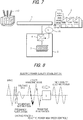
- Fig. 8 shows an example in which the controller operates to obtain a compensation electric power from the energy storage system 5, so as to compensate for various fluctuations of an electric power flowing to the electric power system 1, thereby ensuring a high quality electric power supply.
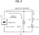
- This example shows a short-time high-output function of the sodium sulfur battery.
- a sodium sulfur single battery (open-circuit voltage 2.075 V), a 28-m ⁇ resistor 17a, a 1-m ⁇ resistor 17b, and a switch 18 are connected in the manner shown in Fig. 9, thereby forming a predetermined circuit.
- a rated discharge is performed on the 28-m ⁇ resistor 17a, the switch 18 is opened or closed so as to effect a short-time high-output discharge on the 1-m ⁇ resistor 17b.
- Fig. 10 (which is a graph) shows the result obtained when a high output discharge is repeated every hour during the rated discharge.
- the sodium sulfur battery based energy storage and power compensation system formed according to the present invention is characterized in that it employs the above described sodium sulfur battery, forming a system capable of performing a load leveling running, as well as providing a function of preventing an instantaneous voltage drop.
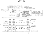
- Fig. 11 shows in detail an example in which the sodium sulfur battery based energy storage and power compensation system 8 formed according to the present invention can be used in an electric load (factory) 2 having a total load of 5 MW.
- a energy storage system 5 including ten units of 500 KW PCSs 4 and sodium sulfur batteries 3 is electrically connected to a high speed semiconductor switch 6, an electric power supply system 1 and an electric load 2, in the manner shown in Fig. 11.
- the energy storage system 5 receives at night an electric charge from the electric power supply system 1, but during daytime when there are increased needs for electric power because a lot of electric load such as air conditioning equipment and air conditioners are in use, the energy storage system 5 discharges 1 MW electric power, thereby effecting load leveling running.
- the high speed switch 6 When there is a voltage sag or a service interruption, the high speed switch 6 operates to immediately shut off the circuit, while at the same time an electric power of 5 MW is spontaneously discharged from the energy storage system 5 within 30 seconds, thereby ensuring a power supply having stabilized quality without any voltage drop, until the service interruption is over and an ordinary power supply has been restored.
- the discharge is indicated as a PQ discharge (Power Quality discharge).
- PQ discharge Power Quality discharge
- a back-up generator not shown
- 30 seconds would be sufficient to bridge the power source from the energy storage system to the back-up generator. Accordingly, even if the service interruption period is relatively long, it is still possible to supply an electric power having a high and stabilized quality to the electric load (factory) 2.
- Fig. 12 shows in detail an example in which a group of spare batteries 19 are arranged for use with a high-temperature battery system of the present invention, which is provided for an electric load having a total load of 10 MW. If, in the event of an accident, a module battery 3 has a failure, the failed group is opened while the spare group 19 can be connected in parallel to the circuit, thereby improving the reliability for supplying an electric power. In such a case, since each group includes 2 module batteries 3, if the system is used for a long time, the second battery also fails, a healthy module battery of the failed group (in opened condition) can be used to replace the second failed battery. In this way, it is possible for the system to run for an extremely long time, ensuring an improved reliability.
- the high-temperature secondary battery based energy storage and power compensation system formed according to the present invention is a system capable of performing peak shaving running as well as load leveling running, thereby ensuring an improved, stable, and high quality electric power supply. Therefore, the energy storage and power compensation system of the present invention is suitable not only for effectively making use of the electric power in the night time, but is also suitable for supplying to a factory or the like facilities a high quality electric power capable of preventing an voltage sag in important equipment, stabilizing an output electric power generated even by fluctuating renewable energy, and which is capable of compensating for spike, frequency fluctuations and harmonic distortions.
Landscapes
- Engineering & Computer Science (AREA)
- Power Engineering (AREA)
- Business, Economics & Management (AREA)
- Emergency Management (AREA)
- Supply And Distribution Of Alternating Current (AREA)
- Secondary Cells (AREA)
- Stand-By Power Supply Arrangements (AREA)
- Charge And Discharge Circuits For Batteries Or The Like (AREA)
Applications Claiming Priority (2)
| Application Number | Priority Date | Filing Date | Title |
|---|---|---|---|
| JP2000146834 | 2000-05-18 | ||
| JP2000146834A JP2001327083A (ja) | 2000-05-18 | 2000-05-18 | 高温二次電池による電力貯蔵及び補償システム |
Publications (2)
| Publication Number | Publication Date |
|---|---|
| EP1156573A2 true EP1156573A2 (de) | 2001-11-21 |
| EP1156573A3 EP1156573A3 (de) | 2004-11-03 |
Family
ID=18653112
Family Applications (1)
| Application Number | Title | Priority Date | Filing Date |
|---|---|---|---|
| EP20010304223 Withdrawn EP1156573A3 (de) | 2000-05-18 | 2001-05-11 | Auf Hochtemperatursekundärbatterien basiertes System zur Speicherung und Leistungskompensation von elektrischer Energie |
Country Status (3)
| Country | Link |
|---|---|
| US (1) | US6747370B2 (de) |
| EP (1) | EP1156573A3 (de) |
| JP (1) | JP2001327083A (de) |
Cited By (23)
| Publication number | Priority date | Publication date | Assignee | Title |
|---|---|---|---|---|
| EP1424760A3 (de) * | 2002-11-26 | 2004-12-22 | Kabushiki Kaisha Toshiba | Energieverwaltungssystem |
| EP1670115A1 (de) * | 2004-12-07 | 2006-06-14 | Meta System S.p.A. | Unterbrechungsfreie Stromversorgung zur Begrenzung der Spitzenleistung |
| ES2268966A1 (es) * | 2005-04-26 | 2007-03-16 | Home Multienergy, S.L. | Unidad de regulacion para alimentacion ininterrumpida de redes de semaforos y otros equipos electricos de mobiliario urbano e interurbano. |
| WO2008121045A1 (en) * | 2007-03-30 | 2008-10-09 | Abb Technology Ltd. | A device and a method for supplying power to a critical load |
| EP1619769A4 (de) * | 2003-03-11 | 2009-08-26 | Toshiba Kk | Gleichstromversorgungssystem und schalter |
| WO2009152849A1 (en) * | 2008-06-17 | 2009-12-23 | Abb Research Ltd | A power apparatus for a high voltage electrical power system |
| EP2071697A3 (de) * | 2007-12-14 | 2010-11-24 | Mazda Motor Corporation | Batterieladeverfahren und Batterieladegerät |
| WO2010135937A1 (en) | 2009-05-27 | 2010-12-02 | Byd Company Limited | Energy storage system for balancing load of power grid |
| WO2011033820A1 (ja) * | 2009-09-16 | 2011-03-24 | 東芝三菱電機産業システム株式会社 | 電力変換システムおよび無停電電源システム |
| WO2011069553A1 (en) * | 2009-12-10 | 2011-06-16 | Abb Research Ltd | A dc power source for a high voltage power apparatus |
| CN102322393A (zh) * | 2009-12-16 | 2012-01-18 | 歌美飒创新技术公司 | 用于提高恢复能量损失的发电量的风轮机控制方法 |
| US8384242B2 (en) | 2008-09-30 | 2013-02-26 | Ngk Insulators, Ltd. | Method for controlling interconnection system |
| EP2487769A4 (de) * | 2009-10-05 | 2013-03-27 | Toyota Motor Co Ltd | Spezifikationsauswahlvorrichtung eines energiespeichersystems und spezifikationsauswahlverfahren für ein energiespeichersystem |
| CN103490400A (zh) * | 2013-08-21 | 2014-01-01 | 安徽国科电力设备有限公司 | 分布式层级过电压控制系统及方法 |
| US8779724B2 (en) | 2009-12-28 | 2014-07-15 | Toyota Jidosha Kabushiki Kaisha | Residential electric power storage system |
| EP2698897A4 (de) * | 2011-04-11 | 2015-06-10 | Ngk Insulators Ltd | Energiespeichervorrichtung und verfahren zum betreiben der energiespeichervorrichtung |
| CN105006876A (zh) * | 2015-08-09 | 2015-10-28 | 青岛威控电气有限公司 | 一种混合储能供电转换装置及转换方法 |
| US9214814B2 (en) | 2008-11-19 | 2015-12-15 | Japan Wind Development Corporation Ltd. | Secondary battery system |
| EP2837080A4 (de) * | 2012-04-12 | 2016-01-27 | East Penn Mfg Co | Verwaltung einer batteriekapazität |
| EP3079038A2 (de) * | 2015-03-26 | 2016-10-12 | Methode Electronics, Inc. | Leistungsspitzenabdeckungssystem |
| EP2190096A4 (de) * | 2008-08-04 | 2016-11-09 | Toshiba Kk | Steuerungsvorrichtung und steuerungsverfahren für eine sekundärbatterie |
| EP3301775A1 (de) * | 2016-09-30 | 2018-04-04 | ABB Schweiz AG | Stromwandlersystem für leistungskompensation und lastausgleich an ein stromverteilungsnetz angeschlossen |
| CN111371173A (zh) * | 2020-03-13 | 2020-07-03 | 青海能高新能源有限公司 | 一种治理三相交流电压暂降的储充放系统及其方法 |
Families Citing this family (63)
| Publication number | Priority date | Publication date | Assignee | Title |
|---|---|---|---|---|
| US6670721B2 (en) * | 2001-07-10 | 2003-12-30 | Abb Ab | System, method, rotating machine and computer program product for enhancing electric power produced by renewable facilities |
| JP2004023860A (ja) * | 2002-06-14 | 2004-01-22 | Tokyo Electric Power Co Inc:The | 瞬低対策機能付き電力貯蔵用ナトリウム−硫黄電池システム |
| WO2004054065A1 (en) | 2002-12-06 | 2004-06-24 | Electric Power Research Institute, Inc. | Uninterruptable power supply and generator system |
| CA2544134A1 (en) * | 2003-10-27 | 2005-05-06 | Ben M. Enis | Storing and using energy to reduce the end-user cost |
| US7939968B2 (en) * | 2004-08-31 | 2011-05-10 | American Power Conversion Corporation | Method and apparatus for providing uninterruptible power |
| JP2006101634A (ja) * | 2004-09-29 | 2006-04-13 | Tokyo Electric Power Co Inc:The | 分散型電源装置 |
| ES2277724B1 (es) * | 2005-02-23 | 2008-06-16 | GAMESA INNOVATION & TECHNOLOGY, S.L. | Procedimiento y dispositivo para inyectar intensidad reactiva durante un hueco de tension de red. |
| US20090234598A1 (en) * | 2006-03-06 | 2009-09-17 | Abb Research Ltd. | Temperature Controller |
| RU2399123C2 (ru) * | 2006-03-06 | 2010-09-10 | Абб Рисерч Лтд | Контроллер температуры |
| RU2388131C1 (ru) * | 2006-03-06 | 2010-04-27 | Абб Рисерч Лтд | Контроллер заряда |
| WO2007102756A1 (en) * | 2006-03-06 | 2007-09-13 | Abb Research Ltd | Temperature controller |
| WO2007102758A1 (en) * | 2006-03-06 | 2007-09-13 | Abb Research Ltd | Power compensator |
| EP2036180B1 (de) * | 2006-06-30 | 2016-11-16 | Abb Research Ltd. | Leistungskompensierer und verfahren zum bereitstellen eines schwarzstarts mit diesem kompensierer |
| JP5073258B2 (ja) * | 2006-09-27 | 2012-11-14 | 日本碍子株式会社 | ナトリウム−硫黄電池の制御方法 |
| JP4796974B2 (ja) * | 2007-01-26 | 2011-10-19 | 株式会社日立産機システム | 風力発電装置と蓄電装置のハイブリッドシステム,風力発電システム,電力制御装置 |
| JP4949902B2 (ja) * | 2007-03-16 | 2012-06-13 | 日本碍子株式会社 | 二次電池の電力制御方法 |
| JP2010530613A (ja) * | 2007-05-10 | 2010-09-09 | オークランド ユニサービシズ リミテッド | 複数の電源を利用する電動車両 |
| EP2160616A1 (de) * | 2007-07-02 | 2010-03-10 | ABB Research LTD | Ladungszustandsbestimmung |
| US20090130539A1 (en) * | 2007-11-20 | 2009-05-21 | Robert Van Burdine | Electric power grid buffer |
| US7944184B2 (en) * | 2008-04-07 | 2011-05-17 | Korea Electric Power Corporation | Static compensator apparatus for HVDC system |
| JP2011517276A (ja) * | 2008-04-18 | 2011-05-26 | エー ビー ビー リサーチ リミテッド | 伝送線路制御のための装置および方法 |
| CN101667735B (zh) * | 2008-09-02 | 2014-04-23 | 日本碍子株式会社 | 二次电池的电力控制方法 |
| KR101442842B1 (ko) * | 2008-09-02 | 2014-09-23 | 엔지케이 인슐레이터 엘티디 | 이차 전지의 전력 제어 방법 |
| CN102144329A (zh) * | 2008-09-30 | 2011-08-03 | 日本碍子株式会社 | 钠硫电池的控制方法 |
| CN102144328B (zh) * | 2008-09-30 | 2013-11-20 | 日本碍子株式会社 | 钠硫电池的控制方法 |
| EP2190097B1 (de) * | 2008-11-25 | 2012-05-16 | ABB Research Ltd. | Verfahren zum Betrieb eines Energiespeichersystems |
| US8847551B2 (en) | 2009-02-09 | 2014-09-30 | Younicos, Inc. | Discharging batteries |
| JP5591247B2 (ja) * | 2009-09-16 | 2014-09-17 | 東芝三菱電機産業システム株式会社 | 電力変換システムおよび無停電電源システム |
| CN102511118B (zh) * | 2009-10-05 | 2014-08-06 | 日本碍子株式会社 | 控制装置、控制装置网以及控制方法 |
| US8471406B2 (en) * | 2009-11-02 | 2013-06-25 | General Electric Company | Controllable energy utilization system and associated method |
| DE102010008061A1 (de) * | 2010-02-16 | 2011-12-15 | Erwin Becker | Umlaufrollenwindturbine und Verfahren zur Stromerzeugung aus Windenergie |
| US8471520B2 (en) | 2010-05-04 | 2013-06-25 | Xtreme Power Inc. | Managing renewable power generation |
| US8558409B2 (en) * | 2010-07-09 | 2013-10-15 | Vestas Wind Systems A/S | High voltage switchgear power supply arrangement for a wind turbine facility |
| JP2012039686A (ja) * | 2010-08-04 | 2012-02-23 | Hitachi Ltd | 蓄電池を用いた系統運用方法 |
| CN102377183A (zh) * | 2010-08-08 | 2012-03-14 | 乐清市登立电表仪器研究所 | 一种高速响应无功控制器 |
| US8853887B2 (en) | 2010-11-12 | 2014-10-07 | Schneider Electric It Corporation | Static bypass switch with built in transfer switch capabilities |
| US8803361B2 (en) | 2011-01-19 | 2014-08-12 | Schneider Electric It Corporation | Apparatus and method for providing uninterruptible power |
| US9893526B2 (en) | 2011-03-25 | 2018-02-13 | Green Charge Networks Llc | Networked power management and demand response |
| US9306396B2 (en) | 2011-03-25 | 2016-04-05 | Green Charge Networks Llc | Utility distribution control system |
| US9837821B2 (en) | 2011-03-25 | 2017-12-05 | Green Charge Networks Llc | Energy allocation for energy storage cooperation |
| CN103748734B (zh) | 2011-08-19 | 2016-09-28 | 日本碍子株式会社 | 控制蓄电池的方法、控制蓄电池的装置和电功率控制系统 |
| DE102011055231A1 (de) | 2011-11-10 | 2013-05-16 | Evonik Industries Ag | Verfahren zur Bereitstellung von Regelleistung |
| DE102011055229A1 (de) | 2011-11-10 | 2013-05-16 | Evonik Degussa Gmbh | Verfahren zur Bereitstellung von Regelleistung mit einem Energiespeicher unter Ausnutzung von Toleranzen bei der Bestimmung der Frequenzabweichung |
| DE102011055230A1 (de) * | 2011-11-10 | 2013-05-23 | Evonik Degussa Gmbh | Verfahren zur Bereitstellung von Regelleistung |
| US9007027B2 (en) | 2012-01-31 | 2015-04-14 | Green Charge Networks Llc | Charge management for energy storage temperature control |
| CN102570880B (zh) * | 2012-02-09 | 2014-05-21 | 贵州电网公司电网规划研究中心 | 一种三相全桥式换流器装置 |
| US9048671B2 (en) | 2012-02-24 | 2015-06-02 | Green Charge Networks Llc | Delayed reactive electrical consumption mitigation |
| CN102709986A (zh) * | 2012-06-20 | 2012-10-03 | 成都信息工程学院 | 串联蓄电池组循环活化与蓄电池冗余备份技术 |
| US10140670B2 (en) | 2012-08-31 | 2018-11-27 | Engie Storage Services Na Llc | Energy management methods and systems based on financial impact |
| US9685887B2 (en) | 2012-10-12 | 2017-06-20 | Younicos Inc. | Controlling power conversion systems |
| US9276425B2 (en) | 2012-12-28 | 2016-03-01 | Younicos Inc. | Power management systems with dynamic target state of charge |
| US9368968B2 (en) | 2012-12-28 | 2016-06-14 | Younicos, Inc. | Responding to local grid events and distributed grid events |
| US9520764B1 (en) | 2013-02-15 | 2016-12-13 | Ideal Power, Inc. | Bi-directional multi-port applications |
| JP2015211616A (ja) * | 2014-04-30 | 2015-11-24 | 株式会社Nttファシリティーズ | 需給管理装置 |
| CN105305421A (zh) * | 2015-10-14 | 2016-02-03 | 株洲变流技术国家工程研究中心有限公司 | 一种统一电能质量控制器的实验系统与方法 |
| US9859703B2 (en) | 2015-11-19 | 2018-01-02 | Shepherd Hydricity, Inc. | Method for using chemical thermodynamics to buffer the voltage of electric circuits and power systems |
| US10999652B2 (en) | 2017-05-24 | 2021-05-04 | Engie Storage Services Na Llc | Energy-based curtailment systems and methods |
| DE102017211690B4 (de) | 2017-07-07 | 2020-07-16 | Bayerische Motoren Werke Aktiengesellschaft | System zum Reduzieren von Lastspitzen in einer elektrischen Anlage |
| US10658841B2 (en) | 2017-07-14 | 2020-05-19 | Engie Storage Services Na Llc | Clustered power generator architecture |
| CN115917911A (zh) * | 2020-05-18 | 2023-04-04 | 博隆能源股份有限公司 | 具有双向逆变器的燃料电池操作方法 |
| AU2021300164B2 (en) * | 2020-06-29 | 2024-06-20 | E2 Ip Holding Llc | Providing rapid threshold amount of power to customer load during transfer between primary and secondary power supplies |
| CN113098126B (zh) * | 2021-04-25 | 2023-01-20 | 广东电网有限责任公司广州供电局 | 电压补偿装置 |
| US11750023B2 (en) | 2021-10-08 | 2023-09-05 | Eagle Technology, Llc | High temperature hybrid battery pack |
Citations (1)
| Publication number | Priority date | Publication date | Assignee | Title |
|---|---|---|---|---|
| US5747887A (en) * | 1991-04-25 | 1998-05-05 | Kundenko Co., Ltd. | Multi-function electric power conversion system |
Family Cites Families (10)
| Publication number | Priority date | Publication date | Assignee | Title |
|---|---|---|---|---|
| US5198698A (en) * | 1991-02-11 | 1993-03-30 | Best Power Technology, Inc. | Auxiliary power supply system for providing dc power on demand |
| DE19516838A1 (de) * | 1995-05-08 | 1996-11-14 | Hagen Batterie Ag | Verfahren und Schaltungsanordnung zur Deckung von Energiespitzenbedarf bei elektrischen Wechselstrom- bzw. Drehstromnetzen |
| JPH0965588A (ja) * | 1995-08-24 | 1997-03-07 | Hitachi Ltd | 電力貯蔵システム |
| US5798633A (en) * | 1996-07-26 | 1998-08-25 | General Electric Company | Battery energy storage power conditioning system |
| JPH10117447A (ja) * | 1996-08-22 | 1998-05-06 | Hitachi Ltd | ナトリウム硫黄電池システム |
| US5767591A (en) * | 1996-09-09 | 1998-06-16 | Active Power, Inc. | Method and apparatus for providing startup power to a genset-backed uninterruptible power supply |
| US6487096B1 (en) * | 1997-09-08 | 2002-11-26 | Capstone Turbine Corporation | Power controller |
| US6215202B1 (en) * | 1998-05-21 | 2001-04-10 | Bechtel Enterprises Inc. | Shunt connected superconducting energy management system having a single switchable connection to the grid |
| JP2000278866A (ja) * | 1999-03-22 | 2000-10-06 | Masaaki Iwata | 電力貯蔵型無停電電源装置 |
| JP3505124B2 (ja) * | 2000-03-28 | 2004-03-08 | 東京電力株式会社 | 非常用電源システム及びそのシステムに用いられる電池内の単電池故障有無を自動検出するシステム |
-
2000
- 2000-05-18 JP JP2000146834A patent/JP2001327083A/ja active Pending
-
2001
- 2001-05-11 US US09/853,535 patent/US6747370B2/en not_active Expired - Lifetime
- 2001-05-11 EP EP20010304223 patent/EP1156573A3/de not_active Withdrawn
Patent Citations (1)
| Publication number | Priority date | Publication date | Assignee | Title |
|---|---|---|---|---|
| US5747887A (en) * | 1991-04-25 | 1998-05-05 | Kundenko Co., Ltd. | Multi-function electric power conversion system |
Cited By (39)
| Publication number | Priority date | Publication date | Assignee | Title |
|---|---|---|---|---|
| EP1424760A3 (de) * | 2002-11-26 | 2004-12-22 | Kabushiki Kaisha Toshiba | Energieverwaltungssystem |
| US7188264B2 (en) | 2002-11-26 | 2007-03-06 | Kabushiki Kaisha Toshiba | Power management system |
| EP1619769A4 (de) * | 2003-03-11 | 2009-08-26 | Toshiba Kk | Gleichstromversorgungssystem und schalter |
| EP1670115A1 (de) * | 2004-12-07 | 2006-06-14 | Meta System S.p.A. | Unterbrechungsfreie Stromversorgung zur Begrenzung der Spitzenleistung |
| ES2268966A1 (es) * | 2005-04-26 | 2007-03-16 | Home Multienergy, S.L. | Unidad de regulacion para alimentacion ininterrumpida de redes de semaforos y otros equipos electricos de mobiliario urbano e interurbano. |
| ES2268966B1 (es) * | 2005-04-26 | 2008-03-01 | Home Multienergy, S.L. | Unidad de regulacion para alimentacion ininterrumpida de redes de semaforos y otros equipos electricos de mobiliario urbano e interurbano. |
| WO2008121045A1 (en) * | 2007-03-30 | 2008-10-09 | Abb Technology Ltd. | A device and a method for supplying power to a critical load |
| EP2071697A3 (de) * | 2007-12-14 | 2010-11-24 | Mazda Motor Corporation | Batterieladeverfahren und Batterieladegerät |
| WO2009152849A1 (en) * | 2008-06-17 | 2009-12-23 | Abb Research Ltd | A power apparatus for a high voltage electrical power system |
| US8330301B2 (en) | 2008-06-17 | 2012-12-11 | Abb Research Ltd. | Power apparatus for a high voltage electrical power system |
| AU2008357927B2 (en) * | 2008-06-17 | 2014-01-30 | Abb Research Ltd | A power apparatus for a high voltage electrical power system |
| EP2190096A4 (de) * | 2008-08-04 | 2016-11-09 | Toshiba Kk | Steuerungsvorrichtung und steuerungsverfahren für eine sekundärbatterie |
| CN102144345B (zh) * | 2008-09-30 | 2013-10-16 | 日本碍子株式会社 | 互联系统的控制方法 |
| EP2330711A4 (de) * | 2008-09-30 | 2017-06-21 | NGK Insulators, Ltd. | Verfahren zur steuerung eines verbindungssystems |
| US8384242B2 (en) | 2008-09-30 | 2013-02-26 | Ngk Insulators, Ltd. | Method for controlling interconnection system |
| US9214814B2 (en) | 2008-11-19 | 2015-12-15 | Japan Wind Development Corporation Ltd. | Secondary battery system |
| WO2010135937A1 (en) | 2009-05-27 | 2010-12-02 | Byd Company Limited | Energy storage system for balancing load of power grid |
| EP2436093A4 (de) * | 2009-05-27 | 2013-07-03 | Byd Co Ltd | Energiespeichersystem zum lastausgleich in stromgittern |
| CN102484393B (zh) * | 2009-09-16 | 2015-11-25 | 东芝三菱电机产业系统株式会社 | 功率转换系统及不间断供电电源系统 |
| WO2011033820A1 (ja) * | 2009-09-16 | 2011-03-24 | 東芝三菱電機産業システム株式会社 | 電力変換システムおよび無停電電源システム |
| US9093861B2 (en) | 2009-09-16 | 2015-07-28 | Toshiba Mitsubishi-Electric Industrial Systems Corporation | Power conversion system and uninterruptible power supply system |
| CN102484393A (zh) * | 2009-09-16 | 2012-05-30 | 东芝三菱电机产业系统株式会社 | 功率转换系统及不间断供电电源系统 |
| EP2487769A4 (de) * | 2009-10-05 | 2013-03-27 | Toyota Motor Co Ltd | Spezifikationsauswahlvorrichtung eines energiespeichersystems und spezifikationsauswahlverfahren für ein energiespeichersystem |
| US8829720B2 (en) | 2009-10-05 | 2014-09-09 | Toyota Jidosha Kabushiki Kaisha | Apparatus for selecting specifications of power storage system and method for selecting specifications of power storage system |
| US8525366B2 (en) | 2009-12-10 | 2013-09-03 | Abb Research Ltd. | DC power source for a high voltage power apparatus |
| WO2011069553A1 (en) * | 2009-12-10 | 2011-06-16 | Abb Research Ltd | A dc power source for a high voltage power apparatus |
| CN102322393A (zh) * | 2009-12-16 | 2012-01-18 | 歌美飒创新技术公司 | 用于提高恢复能量损失的发电量的风轮机控制方法 |
| CN102322393B (zh) * | 2009-12-16 | 2015-12-02 | 歌美飒创新技术公司 | 用于提高恢复能量损失的发电量的风轮机控制方法 |
| US8779724B2 (en) | 2009-12-28 | 2014-07-15 | Toyota Jidosha Kabushiki Kaisha | Residential electric power storage system |
| EP2698897A4 (de) * | 2011-04-11 | 2015-06-10 | Ngk Insulators Ltd | Energiespeichervorrichtung und verfahren zum betreiben der energiespeichervorrichtung |
| US9337654B2 (en) | 2011-04-11 | 2016-05-10 | Ngk Insulators, Ltd. | Power storage device and method for operating power storage device |
| EP2837080A4 (de) * | 2012-04-12 | 2016-01-27 | East Penn Mfg Co | Verwaltung einer batteriekapazität |
| CN103490400B (zh) * | 2013-08-21 | 2017-04-12 | 安徽合凯电气科技股份有限公司 | 分布式层级过电压控制系统及方法 |
| CN103490400A (zh) * | 2013-08-21 | 2014-01-01 | 安徽国科电力设备有限公司 | 分布式层级过电压控制系统及方法 |
| EP3079038A2 (de) * | 2015-03-26 | 2016-10-12 | Methode Electronics, Inc. | Leistungsspitzenabdeckungssystem |
| CN105006876A (zh) * | 2015-08-09 | 2015-10-28 | 青岛威控电气有限公司 | 一种混合储能供电转换装置及转换方法 |
| EP3301775A1 (de) * | 2016-09-30 | 2018-04-04 | ABB Schweiz AG | Stromwandlersystem für leistungskompensation und lastausgleich an ein stromverteilungsnetz angeschlossen |
| WO2018060129A1 (en) * | 2016-09-30 | 2018-04-05 | Abb Schweiz Ag | A power converter system for power quality compensation and load balancing connected to an electric power distribution grid |
| CN111371173A (zh) * | 2020-03-13 | 2020-07-03 | 青海能高新能源有限公司 | 一种治理三相交流电压暂降的储充放系统及其方法 |
Also Published As
| Publication number | Publication date |
|---|---|
| JP2001327083A (ja) | 2001-11-22 |
| US20010043013A1 (en) | 2001-11-22 |
| US6747370B2 (en) | 2004-06-08 |
| EP1156573A3 (de) | 2004-11-03 |
Similar Documents
| Publication | Publication Date | Title |
|---|---|---|
| US6747370B2 (en) | High-temperature secondary battery based energy storage and power compensation system | |
| AU2003293372B2 (en) | Electrical power supply | |
| KR101084215B1 (ko) | 에너지 저장 시스템 및 이의 제어 방법 | |
| KR101041300B1 (ko) | 풍력 발전 기지와 전력 전송 시스템 간의 전력 제어인터페이스 | |
| US8334618B2 (en) | Method and area electric power system detecting islanding by employing controlled reactive power injection by a number of inverters | |
| KR102234527B1 (ko) | 발전 연계형 ESS의 주파수 추종 제어를 이용하는 SoC 관리 장치 및 방법 | |
| JPWO2012070141A1 (ja) | 風力発電設備の出力制御方法及び出力制御装置 | |
| US20090021963A1 (en) | Uninterruptible power supply, connected to a grid | |
| Basu et al. | Comparison of active and reactive power oscillation damping with PV plants | |
| US11929638B2 (en) | Full DC voltage power backup system for wind turbine | |
| JP2019187107A (ja) | 電源システム | |
| Tephiruk et al. | Modeling of rate of change of under frequency relay for microgrid protection | |
| Glassmire et al. | Using virtual synchronous generators to resolve microgrid protection challenges | |
| KR20210142569A (ko) | 에너지 저장시스템(ess),무정전 전원공급 장치(ups) 전환 태양광 발전 시스템 | |
| Liemann et al. | Impact of varying shares of distributed energy resources on voltage stability in electric PowerSystems | |
| Riofrio et al. | Power-to-X (PtX) integration in modern power systems: exploring grid code compliance and technical requirements in Denmark and the United Kingdom | |
| KR101336043B1 (ko) | 태양광발전 시스템을 갖는 비상 전원 시스템의 스위칭 제어회로 | |
| Mattern et al. | Application of inverter-based systems for peak shaving and reactive power management | |
| JP7331562B2 (ja) | 電力需給制御システム、電力需給制御装置、及び電力需給制御方法 | |
| KR20220008793A (ko) | 에너지 저장시스템(ess),무정전 전원공급 장치(ups) 전환 태양광 발전 시스템 | |
| JP2023102730A (ja) | 単独運転検出装置、単独運転検出方法、および、単独運転検出装置を備えたパワーコンディショナ | |
| Krneta et al. | Low-voltage ride-through method of the HVDC transmission system for feeding islanded offshore AC loads | |
| US12597778B2 (en) | Gridforming type curtailment control system and method | |
| JP7617510B2 (ja) | 電源システム | |
| US20250105624A1 (en) | Method for controlling a microgrid and associated microgrid |
Legal Events
| Date | Code | Title | Description |
|---|---|---|---|
| PUAI | Public reference made under article 153(3) epc to a published international application that has entered the european phase |
Free format text: ORIGINAL CODE: 0009012 |
|
| AK | Designated contracting states |
Kind code of ref document: A2 Designated state(s): AT BE CH CY DE DK ES FI FR GB GR IE IT LI LU MC NL PT SE TR |
|
| AX | Request for extension of the european patent |
Free format text: AL;LT;LV;MK;RO;SI |
|
| PUAL | Search report despatched |
Free format text: ORIGINAL CODE: 0009013 |
|
| AK | Designated contracting states |
Kind code of ref document: A3 Designated state(s): AT BE CH CY DE DK ES FI FR GB GR IE IT LI LU MC NL PT SE TR |
|
| AX | Request for extension of the european patent |
Extension state: AL LT LV MK RO SI |
|
| RIC1 | Information provided on ipc code assigned before grant |
Ipc: 7H 02J 3/32 B Ipc: 7H 02J 3/18 B Ipc: 7H 02J 9/06 A |
|
| 17P | Request for examination filed |
Effective date: 20050307 |
|
| AKX | Designation fees paid |
Designated state(s): AT BE CH CY DE DK ES FI FR GB GR IE IT LI LU MC NL PT SE TR |
|
| 17Q | First examination report despatched |
Effective date: 20070227 |
|
| STAA | Information on the status of an ep patent application or granted ep patent |
Free format text: STATUS: THE APPLICATION IS DEEMED TO BE WITHDRAWN |
|
| 18D | Application deemed to be withdrawn |
Effective date: 20070710 |