EP1156612A2 - Fehlerloses Schalten von Datenströmen - Google Patents
Fehlerloses Schalten von Datenströmen Download PDFInfo
- Publication number
- EP1156612A2 EP1156612A2 EP01201754A EP01201754A EP1156612A2 EP 1156612 A2 EP1156612 A2 EP 1156612A2 EP 01201754 A EP01201754 A EP 01201754A EP 01201754 A EP01201754 A EP 01201754A EP 1156612 A2 EP1156612 A2 EP 1156612A2
- Authority
- EP
- European Patent Office
- Prior art keywords
- data stream
- basic
- fragments
- copy
- node
- Prior art date
- Legal status (The legal status is an assumption and is not a legal conclusion. Google has not performed a legal analysis and makes no representation as to the accuracy of the status listed.)
- Withdrawn
Links
- 238000000034 method Methods 0.000 claims abstract description 50
- 239000012634 fragment Substances 0.000 claims description 152
- 230000008707 rearrangement Effects 0.000 claims description 29
- 230000005540 biological transmission Effects 0.000 claims description 23
- 230000001360 synchronised effect Effects 0.000 claims description 9
- 230000001934 delay Effects 0.000 claims description 7
- RGNPBRKPHBKNKX-UHFFFAOYSA-N hexaflumuron Chemical compound C1=C(Cl)C(OC(F)(F)C(F)F)=C(Cl)C=C1NC(=O)NC(=O)C1=C(F)C=CC=C1F RGNPBRKPHBKNKX-UHFFFAOYSA-N 0.000 claims 2
- 239000011159 matrix material Substances 0.000 description 10
- 238000010586 diagram Methods 0.000 description 7
- 238000005457 optimization Methods 0.000 description 7
- 238000004891 communication Methods 0.000 description 4
- 238000005516 engineering process Methods 0.000 description 3
- 230000006870 function Effects 0.000 description 3
- 102100034542 Acyl-CoA (8-3)-desaturase Human genes 0.000 description 2
- 101000848239 Homo sapiens Acyl-CoA (8-3)-desaturase Proteins 0.000 description 2
- 230000006978 adaptation Effects 0.000 description 2
- 230000000903 blocking effect Effects 0.000 description 2
- 230000009977 dual effect Effects 0.000 description 2
- 238000012423 maintenance Methods 0.000 description 2
- 238000012544 monitoring process Methods 0.000 description 2
- 238000010606 normalization Methods 0.000 description 2
- 230000008054 signal transmission Effects 0.000 description 2
- 239000004020 conductor Substances 0.000 description 1
- 238000012790 confirmation Methods 0.000 description 1
- 230000000694 effects Effects 0.000 description 1
- 238000007667 floating Methods 0.000 description 1
- 238000009434 installation Methods 0.000 description 1
- 238000013507 mapping Methods 0.000 description 1
- 230000003287 optical effect Effects 0.000 description 1
- 238000012545 processing Methods 0.000 description 1
- 238000005086 pumping Methods 0.000 description 1
- 230000000979 retarding effect Effects 0.000 description 1
- 238000005096 rolling process Methods 0.000 description 1
- 238000012360 testing method Methods 0.000 description 1
- 238000012546 transfer Methods 0.000 description 1
Images
Classifications
-
- H—ELECTRICITY
- H04—ELECTRIC COMMUNICATION TECHNIQUE
- H04J—MULTIPLEX COMMUNICATION
- H04J3/00—Time-division multiplex systems
- H04J3/02—Details
- H04J3/14—Monitoring arrangements
-
- H—ELECTRICITY
- H04—ELECTRIC COMMUNICATION TECHNIQUE
- H04J—MULTIPLEX COMMUNICATION
- H04J3/00—Time-division multiplex systems
- H04J3/02—Details
- H04J3/06—Synchronising arrangements
- H04J3/062—Synchronisation of signals having the same nominal but fluctuating bit rates, e.g. using buffers
- H04J3/0623—Synchronous multiplexing systems, e.g. synchronous digital hierarchy/synchronous optical network (SDH/SONET), synchronisation with a pointer process
-
- H—ELECTRICITY
- H04—ELECTRIC COMMUNICATION TECHNIQUE
- H04J—MULTIPLEX COMMUNICATION
- H04J2203/00—Aspects of optical multiplex systems other than those covered by H04J14/05 and H04J14/07
- H04J2203/0001—Provisions for broadband connections in integrated services digital network using frames of the Optical Transport Network [OTN] or using synchronous transfer mode [STM], e.g. SONET, SDH
- H04J2203/0057—Operations, administration and maintenance [OAM]
- H04J2203/006—Fault tolerance and recovery
-
- H—ELECTRICITY
- H04—ELECTRIC COMMUNICATION TECHNIQUE
- H04J—MULTIPLEX COMMUNICATION
- H04J2203/00—Aspects of optical multiplex systems other than those covered by H04J14/05 and H04J14/07
- H04J2203/0001—Provisions for broadband connections in integrated services digital network using frames of the Optical Transport Network [OTN] or using synchronous transfer mode [STM], e.g. SONET, SDH
- H04J2203/0089—Multiplexing, e.g. coding, scrambling, SONET
- H04J2203/0096—Serial Concatenation
Definitions
- the present invention relates to a method and a system for switching and rearrangement of data streams transmitted in a telecommunication network.
- the proposed technology is preferably applicable to SONET/SDH telecommunication systems, though it can also be used in PDH systems.
- Synchronous Digital Hierarchy SDH
- SONET Synchronous Optical Network
- SONET and SDH govern interface parameters; rates, formats and multiplexing methods; operations, administration, maintenance and provisioning for high-speed signal transmission.
- SDH and SONET use frame formats transmitted every 125 ⁇ s (8000 frames/s). Because of compatibility between SDH and SONET, their basic frames are similarly structured, but differ in dimension, which fact reflects the basic transmission rates of 155.52 and 51.84 Mb/s, respectively.
- a basic frame format of SDH is 9 rows of 270 byte columns, or 2430 bytes/frame, corresponding to an aggregate frame rate of 155.52 Mb/s.
- the mentioned basic frame transmitted at the rate 155.52 Mb/s forms the fundamental building block called Synchronous Transport Module Level-1.
- SONET systems the basic frame has dimensions of 9 rows by 90 bytes (270:3) and, being transmitted at the rate 51.84 Mb/s (155.52:3), forms the appropriate fundamental building block called Synchronous Transport Signal Level-1 (STS-1).
- both the SDH, and the SONET systems are based on the hierarchical principle of composing higher order signals (so-called high order virtual containers) from lower order signals (so-called lower order virtual containers).
- the STM-1 signal contains a signal called AU-4 that, in turn, carries a signal VC-4.
- the virtual container VC-4 can be mapped from a number of lower order signals.
- the STS-1 signal contains a signal AU-3 that in turn carries a signal VC-3.
- the VC-3 can be composed from several lower order signals.
- SDH also includes signals of Synchronous Transport Level 4, 16 and 64 (so-called VC4-N) which constitute 4, 16 or 64 independent VC-4 signals.
- VC4-N Synchronous Transport Level 4
- SDH and SONET are known to support data streams having rates higher than the fundamental building block. If there are services requiring a capacity greater than 155Mbps, one needs a vehicle to transport the payloads of these services.
- concatenated signals for example VC4-Nc, are designed for this purpose.
- STM-4 signal having a data rate 622.08 Mb/s (4 x 155.52 Mb/s) is one of the high order signals in the SDH system.
- Payload of the STM-4 signal is generated by byte-interleavingly multiplexing four payloads of STM-1 (or four AU4, or four VC4) signals.
- Concatenated VC4 (VC4-Nc) is characterized by a common synchronous payload envelope being the N-fold VC4 signal, and by a common column of service bytes called POH (Path Overhead); for transmitting, such a signal needs a number of adjacent time-slots.
- TDM Time Division Multiplexing
- a byte-interleaving multiplexer intermittently transmits bytes of the 10 containers via an optic link in a manner that specific time slots are assigned to bytes of the respective specific containers.
- the optic link allows for transmitting bytes in 16 timeslots, with a frequency 2.5 GHz, which is sufficient for a high rate SDH signal STM16.
- the initial arrangement at the transmitter side is such that bytes of VC4 containers Nos. 1 to 5 are sent in respective time slots 1 to 5, and bytes of VC4 Nos.6 to 10 are transmitted in time slots 9 to 13.
- a new signal should be transmitted via the same optic link, and the bandwidth of the link would theoretically allow it (i.e., there are vacant time slots).
- a simple sum of the vacant time slots might be insufficient for transmitting the new signal if it requires several adjacent (sequential) slots.
- a concatenated signal VC4-4c requires 4 adjacent time slots for its transmission, and in our example we don't have such slots available. It would therefore be useful to regroup the transmitted 10 separate VC4s so as to free one window of four consequent time slots for transmitting the new, concatenated signal.
- each AU4 signal contains 30 lower order signals (containers) TU12.
- 63 TU12 signals might be mapped in one AU4 container.
- the second AU4 container would be vacant for transmitting an additional signal, for example a new VC4 signal that requires almost the whole AU4 capacity.
- One AU4 container comprises one VC4 container and an additional 9-byte row of so-called Administrative Unit pointers that serve, inter alia , for allocating the beginning of a VC4 payload in the frame of the transmitted signal).
- US Patent No.5,987,027 to Alcatel describes a connection procedure for finding by rearrangement a path for multirate, multicast traffic through an SDH cross-connect. If no free path for a new payload through the SDH switching hardware is available, the switching procedure looks for a path that is adequate and blocked by the least existing payload capacity. Connections for existing payloads that must be moved to make way for the new payload are queued and the connection procedure is applied recursively, to each in turn, until the queue is empty.
- US patent No. 5,408,231 to Alcatel Network Systems relates to a method and system for finding a path through a communication matrix (forming part of a cross-connect network element), preferably in a rearrangeable matrix.
- the method performs a so-called process of pumping the input stage array, output stage array and center stage array of the matrix using information on the idle input link array and the idle output link array to determine an optimal center stage switch.
- US patent No. 5,343,194 to Alcatel Network Systems also discloses a method to immediately connect and reswitch connection configurations through a rearrangeable communications matrix, using an optimization procedure that targets the minimal possible rearrangements.
- US patent No. 5,345,441 to AT&T Bell Laboratories describes a procedure of hierarchical path hunt for establishing a switched connection of a given bandwidth as a collection of a plurality of connections of smaller bandwidths of different sizes.
- the path hunt uses a hierarchy of status tables, corresponding to the hierarchy of rates, for each time switching element in the network.
- the path-hunt follows a search hierarchy for lower-rate connections that first searches for matching partially full time-slot entries in higher rate status tables, and uses idle time-slot entries in higher-rate status tables only as a last resort.
- US patent No. 4,417,244 to IBM corp. discloses yet another method for rearranging a three stage (primary, intermediate, tertiary) switching network to permit data to be transmitted from any primary outlet to any given tertiary inlet.
- Two call rearranging buses are provided to assure that each signal path being rearranged is maintained to prevent data transmission dropout.
- Primary to intermediate and intermediate to tertiary paths are rearranged one at a time using the call rearranging buses to move free primary and tertiary links to a single intermediate matrix. It should be noted that, for rearrangement, some existing connections are to be broken and then made again in a queue.
- US 5482469 relates to a dual monitor self-contained six port digital signal cross-connect module.
- a housing with a compact, self-contained, six jack port, dual monitor, digital signal cross-connect switching module.
- a first monitor jack port and a second monitor jack port are mounted in the housing, each being adapted to receive an electrical plug.
- a plurality of modules comprise a system having provisions for cross-connect switching, rerouting, repair, patch and roll and monitoring.
- the six jack port digital switching module paired with a like unit has an input jack port, an output jack port, a cross-connect input jack port, a cross-connect output jack port, and four multi-purpose monitor jack ports.
- US 6018576 relates to a method and an apparatus for automated node-based normalization after restoration of a network.
- the end nodes After a failure in the network is repaired and a specified time period is passed, the end nodes perform a sequence of tasks to execute a modified form of a path-and-roll normalization.
- the process of switching from the restoral route to the original fixed route is performed under the patch-and-roll method, according to which each end node transmits traffic over both a restoral route and the original traffic route that has been fixed.
- Each end node confirms receipt of signals over the fixed traffic route.
- each end node switches to receiving live traffic from the restoral route to the fixed traffic route and stops transmitting over the restoral traffic route.
- the end nodes finally instruct the other nodes along the restoral route to disconnect the restoral route.
- the confirmation message ensures that both of the end nodes receive the live traffic over the original, fixed traffic route so that at no time is traffic disrupted in the network.
- US 6018576 neither describes nor suggests how the goal of non-disruption of the live traffic in the network can really be achieved.
- the method is advantageous in that it allows errorless rearrangement for transmitting one or more extra data streams via the path, and/or allows network optimization to be provided by errorless switching one or more data streams to alternative routes in the network.
- the data streams mentioned in the present application are preferably SDH/SONET or PDH data streams.
- a method of errorless switching, in a telecommunication network, from a basic data stream to a copy of the basic data stream obtained by bridging of the basic data stream at a first network node the method being characterized in that the switching is performed at a second network node receiving both the basic data stream and the copy data stream, upon performing an operation of delay equalization between the basic data stream and the copy data stream.
- the method is applied for on-line rearrangement of an original data stream composed of two or more fragment data streams (so-called basic fragments) transmitted in respective time-slots, wherein some vacant data slots exist in the original data stream;
- the method is characterized in that the rearrangement is decentralized, i.e., performed using the first and the second network nodes interconnected by a telecommunication path, wherein at least one of said basic fragments is bridged at the first node to obtain a copy fragment, said basic fragment and said obtained copy fragment are transmitted to the second node and wherein, at the second node, said copied basic fragment is dropped upon equalizing delays between it and its copy fragment, thereby ensuring substantially errorless rearrangement and obtaining a rearranged data stream.
- the rearrangement is decentralized, i.e., performed using the first and the second network nodes interconnected by a telecommunication path, wherein at least one of said basic fragments is bridged at the first node to obtain a copy fragment, said basic fragment and said obtained copy
- the telecommunication path is, in general, any telecommunication link having capacity not smaller than the maximal capacity of the original data stream with the vacant data slots.
- the telecommunication path may comprise one or more transmission lines.
- the method includes the following steps:
- the method may be accomplished in various modes. If it is effected in one stage, "n" basic fragments are simultaneously bridged to free "n" original time-slots required for transmitting a new signal. In an alternative mode, the method is effected by stages when one or more basic fragments are bridged at a time so that a part of the required original time-slots is freed, and the whole cycle is repeated up to the required number of the original time-slots are cleared for transmitting a new signal(s).
- the step of bridging in the first node is performed by entering each of said at least one basic fragments to an input of a cross-connect device (a switching matrix thereof), providing a pair of connections in the cross-connect device for each of said fragments to connect its associated input to a pair of outputs, and outputting from the pair of outputs a bridged pair of identical fragments for further multiplexing them in two different time-slots.
- a cross-connect device a switching matrix thereof
- the step of multiplexing just ensures that one fragment of each of the bridged pairs occupies the original time-slot of the bridged basic fragment, and the other fragment (i.e. the copy) occupies a vacant time-slot.
- the step of freeing said at least one original time-slots is accomplished for-each particular slot by canceling one of the pair of connections in the cross-connection device so, that the output corresponding to the particular basic time-slot is disconnected from its corresponding input. It means, that inputs of all "copied" basic fragments to the cross-connect device will remain connected only with outputs associated with vacant time-slots. The cleared "original time-slots" outputs can now be re-connected to any vacant inputs of the cross-connect device for receiving a new signal.
- said delay equalizing operation comprises a step of pointers' justification with respect to at least one copy fragment and its corresponding basic fragment, and wherein pointers of said basic fragment and the corresponding copy fragment serve mutual references to one another.
- positions of the pointers are mutually adjusted, thereby synchronizing payloads of standard frames of the pair of the bridged data streams.
- a system for errorless switching, in a telecommunication network, from a basic data stream to a copy of the basic data stream obtained by bridging of the basic data stream comprises a first network node interconnected with a second network node via a telecommunication path; said first node being capable of bridging said basic data stream, said second network being intended for receiving both the basic data stream and the copy data stream; the system also comprising a network management block and a delay equalizing means operative to perform delay equalization between the basic data stream and the copy data stream before dropping the basic data stream.
- the system forms part of a system for on-line rearranging an original data stream composed of original fragment data streams (basic fragments) transmitted in respective original time-slots while one or more vacant data slots exist in the original data stream; in this embodiment, said basic data stream constitutes one of said basic fragments, and said copy data stream constitutes a copy fragment occupying one of said vacant time slots and obtained by bridging said basic fragment.
- the data stream is preferably an SDH/SONET or a PDH data stream.
- the telecommunication path is, in general, any telecommunication link having capacity not smaller than the maximal capacity of the original data stream with the vacant data slots.
- the telecommunication path may comprise one or more transmission lines.
- each of the nodes includes a Network Element (NE) comprising a cross-connect device (being a switching matrix) having an input stage and an output stage, and a control unit.
- NE Network Element
- the 1 st node is provided with a MUX unit connected to the output stage of the 1 st cross-connect
- the 2 nd node is provided with a DEMUX unit connected to the input stage of the 2 nd cross-connect.
- the 2 nd node is also provided with the delay equalizing means, which is preferably connected between the DEMUX and the 2 nd cross-connect.
- the intermediate communication link preferably couples the output of MUX with the input of the DEMUX.
- the MUX unit may comprise one or more multiplexers.
- TDM Multiplexer may constitute a number of TDM MUX blocks arranged in one or more cascades.
- the DEMUX unit may contain one or more demultiplexers (say, a TDM DEMUX or a cascade thereof).
- the network management block via the network nodes' control units, is responsible of causing:
- the forming of the rearranged data stream outgoing from the 2 nd cross-connect is performed by causing said 2 nd cross-connect to create internal connections only for the copies and not for the copied basic fragments.
- the freeing of the data slots corresponding to the "n" basic fragments at the 1 st node can be achieved by causing the 1 st cross-connect to drop the "original, direct" connections which existed between the input stage and the output stage of the 1 st cross-connect for the "n" basic fragments before the beginning of the rearrangement process.
- the delay equalization means comprises at least one unit capable of performing pointers' justification for a pair of bridged fragments, by using thereof as reference for one another.
- Such a unit may serve for equalizing delays of one bridged pair at a time, and be used cyclically under supervision of the control unit.
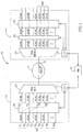
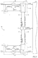
- Fig. 1 shows a schematic block-diagram of an exemplary system implementing the method according to the invention.
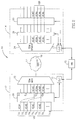
- Fig. 2 schematically illustrates the rearranged data stream and the freed time-slots ready for transmission of a new signal in the bandwidth of the original data stream, using the bloc-diagram of Fig. 1.
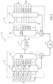
- Fig. 3 schematically illustrates transmission of a new signal together with the rearranged original data stream.
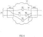
- Fig. 4 schematically illustrates rearrangement in a network for the network optimization.
- Fig. 5 illustrates a schematic block-diagram explaining the principle of delay equalization using pointers' justification.
- the present invention will further be described in more detail using an example of an SDH data stream transmission.
- the original data stream comprises a number of fragment data streams (in the frame of this application, a number of so-called basic fragments) transmitted in respective original time slots.
- Fig. 1 illustrates a schematic block-diagram of the basic embodiment 10 of the proposed system for rearrangement of data streams.
- the system comprises a 1 st node 12 connected to the 2 nd node 14 by a telecommunication path 16 in a network 17, in this embodiment the path constitutes a single transmission link. It should be noted that two or more parallel links may be provided to interconnect the nodes 12 and 14.
- the system also comprises a network manager block 15 connected to control units 11 and 13 of the first and second nodes, respectively.
- An incoming original data stream, generally marked 18, arrives to the system in the demultiplexed form.
- the original data stream carries eight fragment data streams (fragments) VC4 occupying all odd time-slots (schematically indicated as S1, S3, S5...S15) from the available sixteen time slots of the original data stream. All even slots of the data stream are-vacant (S2,...,S16).
- S1, S3, S5...S15 All even slots of the data stream are-vacant (S2,...,S16).
- S2,...,S16 All even slots of the data stream are-vacant
- the mentioned new signal needs four consequent time-slots for its transmission. Though there are eight vacant time-slots in the data stream 18, the requirement cannot be met at the present arrangement, since the vacant time-slots are "loosely spread" over the data stream.
- All the basic fragments are applied to the input stage of a cross-connect 20 of the first node 12 (i.e., the 1 st cross-connect).
- the cross-connect 20 under control of the network manager 15 via the control unit 11, copies (doubles, or "bridges") two fragments following in the time-slots S1 and S3 so that at the output stage of the cross-connect 20 two identical fragments can be found for each basic fragment.
- the 1 st cross-connect 20 performs connections so that the basic fragment VC4A appears at the output stage at a contact assigned to the time slot S1, and a copy fragment VC4a appears at a contact of the output stage, associated with the time-slot S6.
- a TDM multiplexer 22 provides multiplexing of all the fragments outgoing from the output stage of the cross-connect 20, according to their assigned time slots and transmits via the communication link 16 an intermediate data stream marked 18+ ⁇ .
- the intermediate data stream comprises all the fragments of the original data stream 18 and additional two copied fragments (VC4a and VC4b).
- a TDM demultiplexer 24 splits the intermediate data stream into the component fragments, whereupon the delay equalization is provided in block 26.
- the delay equalization is effected for the two copied pairs of fragments: VC4A relative to VC4a, and VC4B relative to VC4b.
- the delay equalizing block 26 is controlled by the control unit 13 and is capable of applying its functions to any pair of fragments indicated by the control unit.
- the fragments, which underwent the delay equalization, are marked with (') in Fig. 1.
- the control unit 13 ensures that the 2 nd cross-connect 28 takes care of all fragments except for the fragments VC4A' and VC4B' (i.e., no output contacts are created for these two fragments at the output stage of the cross-connect 28).
- Fig. 2 shows the block-diagram of Fig. 1 with changes which can be introduced upon forming the rearranged data stream 18R.
- the control unit 13 of the first node communicates with the network manager 15, and the latter instructs the control unit 11 of the first node.
- the 1 st crossconnect 20, according to a command provided by the control unit 11, drops internal connections between the incoming "n" original data fragments and the outputs assigned to their original time-slots. Consequently, the intermediate data stream becomes equal to the rearranged data stream and, beginning from the output stage of the 1 st cross-connect 20 up to the output stage of the 2 nd crossconnect 28, the first four time-slots S1 to S4 become vacant. The rearrangement is completed.
- One of the results is that the network is optimized.
- optimization of the network may be the sole object of the rearrangement operation.
- One example of rearrangement provided in order to optimize transmission of the initial data stream in the network between two reference nodes will be illustrated in Fig. 4.
- the system shown in Fig. 2 is now ready for transmitting a new signal in addition to the rearranged data stream.
- the following stage is illustrated in Fig. 3.
- Fig. 3 depicts how a new signal N consisting of four fragments (schematically depicted as four waved lines) can be applied to the system 10 and be transmitted via four consequent time-slots together with the original data stream 18.
- the step of switching the new signal "in” requires new connections to be created in the 1 st cross-connect, so it may actually replace the step of dropping the excessive connections. Indeed, creating a new connection to an output contact of the cross-connect will automatically cause dropping of any previous connection if existed at this contact.
- Fig. 4 illustrates how the rearrangement procedure can be used for network optimization.
- an original data stream 25 enters a first end-node (Network Element N1 comprising a cross-connect matrix) and is transmitted therefrom via the network 17 (say, IP) to a second end-node (Network Element N2 comprising a cross-connect matrix).
- the data is transmitted between the nodes N1 and N2 in the form of an intermediate data stream capturing two routes in the network. These two routes form together a combined transmission path 27.
- Each of the routes has an individual number of intermediate network elements NE i and, therefore, has its individual transmission properties.
- Alternative routes may exist in the network, which could be capable of providing other conditions of transmission (say, at least one of the alternative routes may be shorter and/or comprise a smaller number of intermediate network elements than one of the existing routes; for example - route 29 seems preferable than the actual route having two intermediate NE i ). If such routes are found, the data stream can be rearranged on-line, similar to that as described above.
- the network optimization can be provided for a data stream comprising at least one fragment routed via a basic route in the network between a first node and a second node, by bridging said at least one fragment at the fist node to obtain a copy of the fragment, routing said copy via an alternative preferred route in the network (for example, by using free outputs and inputs of the end-node cross-connects), performing a delay equalization operation with respect to the fragment and its copy at the second node, and abandoning said basic route while preserving said alternative preferred route.
- the second node NE2 performs a switching operation with delay equalization, so that the copy fragment precisely identical to the basic fragment will be used.
- One embodiment of the precise delay equalization means will be described below.
- Fig. 5 illustrates how the delay-equalizing step can be accomplished when performing switching or rearrangement of SDH/SONET signals.
- a unit for equalizing delays of a particular pair of bridged fragments is based on a so-called pointers justification operation, using FIFO blocks with controllable depth.
- the delay equalizing means may comprise any delay difference minimizing block fulfilled by a precise delay equalization unit such as the one illustrated.
- the most powerfill delay equalization means there are as many units as required to perform the delay equalization for all fragments outgoing from a particular DEMUX (see Figs 1 to 3).
- the simplest delay equalizing means may comprise only one such unit.
- the single unit can be used for performing errorless network optimization when one route is replaced with another; in case a number of fragments are to be rerouted (say, for a data stream rearrangement), the errorless switching will be performed step by step.
- the fragments in this patent application are called and illustrated as VC-n containers of SONET/SDH, each of them comprises pointers and thus actually comprises either an AU-n container for high order signals, or TU-container for low order ones.
- Fig 5 shows a block diagram of a single unit (marked 30) of the delay equalization means; the unit can be implemented by means of hardware & software.
- the rearrangement is provided for transferring a data stream fragment originally transmitted in one (original) time slot, to another (vacant) time slot.
- the unit is operative to take care of two fragments: VC4A transmitted in the original time-slot and VC4a (a copy fragment of VCA) transmitted in a vacant time-slot.
- two symmetric branches of the unit simultaneously take care of a pair of bridged fragments.
- the delay equalization of the fragments is preferably implemented using a so-called operation of pointers' justification.
- the operation of AU (Administrative Unit) pointers' justification is known in the theory and practice of SONET/SDH.
- Position of AU pointer bytes in the standard frame of a data stream indicates where the informational payload begins in this frame (i.e., position of the pointer indicates the floating phase and consequently, the timing of the payload).
- the operation of pointers' justification allows shifting the position of the informational payload's beginning by deliberately changing offset of its pointer bytes by stuffing.
- a positive pointer justification (so-called increment) can be applied for retarding a next frame payload of a particular fragment data stream.
- a negative justification decrement
- the proposed block-diagram of the delay equalizing unit 30 utilizes two symmetric branches 32 and 34, where each of them performs functions of a so-called adaptation layer known in the procedure of processing SONET/SDH signals.
- the branches are interconnected via a control unit, for example via the control unit 13 of the second node 14 (see Fig. 1).
- branch 32 Depending on the incoming signal which may be either a high order signal or a low order signal, and depending on the position of its pointers indicating the initial increment/decrement in the fragment's particular frame (and, consequently, the beginning of the payload therein), branch 32 (34) enables writing the current payload into a FIFO 38 (39), sets clocks of the FIFO and of the output signal, and prepares pointers' generation for a suitable outgoing signal. It should be noted that states (depths) of FIFOs in the two different branches may "historically" differ from one another due to different positions of pointers in previous frames, and may therefore result in different positions of pointers of the outgoing signals.
- the branches interact via the control unit to exchange information on the prepared outgoing pointers, so that the two fragments (i.e., standard frames thereof) serve as mutual references to one another.
- clock of the FIFO (the read clock) of one branch can be-changed to be synchronous with the clock of the other branch.
- a fragment comprising VC4A (which initially occupied one of the original time-slots) enters branch 32 of the unit 30 and its payload is ready to be fed to a FIFO memory block 38.
- a Pointer Interpreter (block 36) watches pointers of a particular frame of the fragment VC4A and transmits the information to a Pointer Generator block 40. According to the initial shift of the pointers (i.e., increment/decrement), the informational payload of the frame will be written into the FIFO 38 (see the commands "enable” and "write”). Information on the initial increment/decrement of the pointers is entered into the Pointer Generator Block 40. Information on the state of FIFO 38 is also introduced into the block 40.
- the Pointer Generator 40 Based on the pointers' initial position, the FIFO clock and the outgoing signal clock, the Pointer Generator 40 prepares pointers of the outgoing signal (actual pointers). Similar operations are performed at the branch 34 with the copy fragment VC4a (which is intended to occupy a vacant time slot). Each of the Pointer Generators 40 and 41 informs the control unit 13 about the corresponding actual pointers' position (arrows 33 and 35). Based on this information, the control unit 13 issues to at least one of the Pointer Generators an increment/decrement request (arrows 47 and/or 45), so as to synchronize the timing of the two payloads under treatment by influencing pointers of the suitable fragment's frame.
- the increment/decrement requests are introduced with the aid of software of the network manager.
- the pointer generators 40 and 41 issue suitable increment/decrement instructions (which retard or accelerate the frame) to the respective FIFO blocks 38 and 39, thereby changing depths of the FIFOs.
- the two payloads, while being read from the FIFO blocks, are accompanied by newly generated pointers, which incorporate the requested increment(s)/decrement(s).
- the two frames can then be issued from the parallel branches of the unit, as portions of synchronous fragments VC4A' and VC4a'; timing of the payloads in these frames will be identical.
- the control unit 13 only one of the fragments (namely, the copy VC4a') will be enabled by the control unit 13 to enter the 2 nd cross-connect 28.
- the 2 nd cross-connect will create internal connection only for this fragment, out of the two illustrated in Fig. 4, so as to output the copy fragment VC4a' in the combination of the rearranged data stream (not shown).
- the enabling instruction of the block 13 may be used to output from the delay equalizing unit 30 only the selected fragment while blocking the second one.
Landscapes
- Engineering & Computer Science (AREA)
- Computer Networks & Wireless Communication (AREA)
- Signal Processing (AREA)
- Computer Hardware Design (AREA)
- Time-Division Multiplex Systems (AREA)
- Detection And Prevention Of Errors In Transmission (AREA)
Applications Claiming Priority (2)
| Application Number | Priority Date | Filing Date | Title |
|---|---|---|---|
| IL13617600 | 2000-05-16 | ||
| IL13617600A IL136176A (en) | 2000-05-16 | 2000-05-16 | Rearrangement of data streams |
Publications (2)
| Publication Number | Publication Date |
|---|---|
| EP1156612A2 true EP1156612A2 (de) | 2001-11-21 |
| EP1156612A3 EP1156612A3 (de) | 2005-09-07 |
Family
ID=11074130
Family Applications (1)
| Application Number | Title | Priority Date | Filing Date |
|---|---|---|---|
| EP01201754A Withdrawn EP1156612A3 (de) | 2000-05-16 | 2001-05-11 | Fehlerloses Schalten von Datenströmen |
Country Status (4)
| Country | Link |
|---|---|
| US (1) | US7023848B2 (de) |
| EP (1) | EP1156612A3 (de) |
| CA (1) | CA2347574C (de) |
| IL (1) | IL136176A (de) |
Families Citing this family (14)
| Publication number | Priority date | Publication date | Assignee | Title |
|---|---|---|---|---|
| US7003086B1 (en) | 2001-01-18 | 2006-02-21 | Cisco Technology, Inc. | Apparatus and method for allocating call resources during a conference call |
| US7046660B2 (en) * | 2001-10-03 | 2006-05-16 | Internet Machines Corp. | Switching apparatus for high speed channels using multiple parallel lower speed channels while maintaining data rate |
| WO2003032555A2 (en) | 2001-10-05 | 2003-04-17 | Aware, Inc. | Systems and methods for multi-pair atm over dsl |
| US7292568B2 (en) * | 2002-06-27 | 2007-11-06 | Alcatel-Lucent Canada Inc. | Timeslot interchange switch |
| US7688833B2 (en) * | 2002-08-30 | 2010-03-30 | Nortel Networks Limited | Synchronous transmission network node |
| US8204085B1 (en) * | 2003-12-15 | 2012-06-19 | Ciena Corporation | Virtual concatenation for parallel data streams |
| GB0506059D0 (en) * | 2005-03-24 | 2005-05-04 | Ibm | Methods and apparatus for switching between data streams |
| US7715309B2 (en) * | 2006-05-24 | 2010-05-11 | At&T Intellectual Property I, L.P. | Method and apparatus for reliable communications in a packet network |
| US7827299B2 (en) * | 2007-09-11 | 2010-11-02 | International Business Machines Corporation | Transitioning between historical and real time data streams in the processing of data change messages |
| US8055785B2 (en) * | 2008-09-17 | 2011-11-08 | Futurewei Technologies, Inc. | Rate control for stream switching |
| EP2466803B1 (de) * | 2010-12-15 | 2013-04-17 | Siemens Aktiengesellschaft | Verfahren zur Datenübertragung in einem Automatisierungssystem unter Verwendung von Dynamic Frame Packing |
| US20130170450A1 (en) * | 2011-12-29 | 2013-07-04 | Qualcomm Incorporated | Wireless broadcast/multicast service capacity over different link budgets and overlay networks |
| US10462218B1 (en) | 2015-07-15 | 2019-10-29 | Google Llc | System and method for sending proposals within a distributed state machine replication system |
| FR3093198B1 (fr) * | 2019-02-22 | 2021-02-12 | St Microelectronics Grenoble 2 | Transmission de données liées sur bus I2C |
Family Cites Families (27)
| Publication number | Priority date | Publication date | Assignee | Title |
|---|---|---|---|---|
| US3786192A (en) * | 1972-10-11 | 1974-01-15 | Bell Telephone Labor Inc | Shift circuits with output control gated by combined control memory |
| US4417244A (en) | 1981-09-01 | 1983-11-22 | International Business Machines Corp. | Automatic path rearrangement for blocking switching matrix |
| US4754454A (en) * | 1986-11-17 | 1988-06-28 | Gte Communication Systems Corporation | Synchronization circuitry for duplex digital span equipment |
| US5119368A (en) * | 1990-04-10 | 1992-06-02 | At&T Bell Laboratories | High-speed time-division switching system |
| US5303267A (en) * | 1992-05-04 | 1994-04-12 | Dsc Communications Corporation | Multipoint data communications system |
| ATE188321T1 (de) | 1992-05-14 | 2000-01-15 | Cit Alcatel | Verfahren zur wegeauswahl in einem vermittlungsnetz |
| US5343194A (en) | 1992-05-14 | 1994-08-30 | Alcatel Network Systems, Inc. | Methods and system for immediately connecting and reswitching digital cross-connect networks |
| US5345441A (en) | 1992-10-20 | 1994-09-06 | At&T Bell Laboratories | Hierarchical path hunt for multirate connections |
| US5359601A (en) * | 1992-10-30 | 1994-10-25 | Scientific-Atlanta, Inc. | Apparatus providing dynamic virtual service selection in a multi-service communications system |
| US5482469A (en) * | 1993-07-21 | 1996-01-09 | Trimm, Inc. | Dual monitor self-contained six port digital signal cross-connect module |
| US5586264A (en) * | 1994-09-08 | 1996-12-17 | Ibm Corporation | Video optimized media streamer with cache management |
| US5497363A (en) * | 1994-09-29 | 1996-03-05 | Alcatel Network Systems, Inc. | Expansion shelf for access system and switch block therefor |
| JP3293743B2 (ja) * | 1996-07-10 | 2002-06-17 | 富士通株式会社 | 時分割信号交換システム |
| US5862135A (en) * | 1996-10-10 | 1999-01-19 | Lucent Technologies Inc. | Simplified interface to a time-division multiplexed communications medium |
| US5987027A (en) * | 1996-11-08 | 1999-11-16 | Alcatel | Cross-connect multirate/multicast SDH/SONET rearrangement procedure and cross-connect using same |
| US6018576A (en) * | 1996-12-31 | 2000-01-25 | Mci Communications Corporation | Method and apparatus for automated node-based normalization after network restoration |
| GB9719895D0 (en) * | 1997-09-18 | 1997-11-19 | British Telecomm | A method of obtaining an optical signal stream |
| GB9805860D0 (en) * | 1998-03-20 | 1998-05-13 | Philips Electronics Nv | Timing control of transmission time slot |
| US6600741B1 (en) * | 1999-03-25 | 2003-07-29 | Lucent Technologies Inc. | Large combined broadband and narrowband switch |
| US6195330B1 (en) * | 1998-11-05 | 2001-02-27 | David C. Sawey | Method and system for hit-less switching |
| JP3808647B2 (ja) * | 1998-12-09 | 2006-08-16 | 富士通株式会社 | セル交換モジュール、伝送装置及び伝送装置における現用・予備切り替え方法 |
| US6804226B1 (en) * | 1998-12-31 | 2004-10-12 | At&T Corp. | Method and apparatus for connecting local subscribers to a LAN |
| US6271946B1 (en) * | 1999-01-25 | 2001-08-07 | Telcordia Technologies, Inc. | Optical layer survivability and security system using optical label switching and high-speed optical header generation and detection |
| JP2001044961A (ja) * | 1999-08-02 | 2001-02-16 | Fujitsu Ltd | 時分割多重装置 |
| US6826201B2 (en) * | 2000-12-19 | 2004-11-30 | Nortel Networks Limited | Multiplexing SONET /SDH data streams using independent encoding schemes |
| US6768871B2 (en) * | 2001-01-30 | 2004-07-27 | The Regents Of The University Of California | Optical layer multicasting using a multicast switch to effect survivability and security |
| US7197031B2 (en) * | 2001-11-26 | 2007-03-27 | Nortel Networks Limited | Cross-connection of high bandwidth signal traffic across independent parallel shelves |
-
2000
- 2000-05-16 IL IL13617600A patent/IL136176A/en not_active IP Right Cessation
-
2001
- 2001-05-11 EP EP01201754A patent/EP1156612A3/de not_active Withdrawn
- 2001-05-15 CA CA002347574A patent/CA2347574C/en not_active Expired - Fee Related
- 2001-05-16 US US09/855,730 patent/US7023848B2/en not_active Expired - Lifetime
Also Published As
| Publication number | Publication date |
|---|---|
| US20020006128A1 (en) | 2002-01-17 |
| EP1156612A3 (de) | 2005-09-07 |
| CA2347574C (en) | 2008-11-25 |
| IL136176A (en) | 2004-02-19 |
| IL136176A0 (en) | 2001-05-20 |
| US7023848B2 (en) | 2006-04-04 |
| CA2347574A1 (en) | 2001-11-16 |
Similar Documents
| Publication | Publication Date | Title |
|---|---|---|
| US5850387A (en) | Processor device for terminating and creating synchronous transport signals | |
| EP0559090B1 (de) | Netzwerkelement mit Querverbindungsmatrix und Server | |
| US5757793A (en) | Integrated multi-rate cross-connect system | |
| CA2490792C (en) | Transparent flexible concatenation | |
| US6556593B1 (en) | Digital cross connect and add/drop multiplexing device for SDH or SONET signals | |
| JP3159862B2 (ja) | 加入者系伝送装置 | |
| US7339936B2 (en) | Switching device for telecommunication networks | |
| US5416768A (en) | Interconnecting communications networks | |
| US7023848B2 (en) | Rearrangement of data streams | |
| JPWO1993013615A1 (ja) | 通信ネットワークの相互接続 | |
| EP0505062B1 (de) | Übertragung von Multiplexdaten in einem Ring | |
| JP3429309B2 (ja) | 同期デジタル遠隔通信システムにおけるエラスティックバッファメモリの充填率を監視する方法及び装置 | |
| US7688833B2 (en) | Synchronous transmission network node | |
| US20010053146A1 (en) | Processor device for terminating and creating synchronous transport signals | |
| US6836486B2 (en) | Switching of low order data structures using a high order switch | |
| EP0957603B1 (de) | Integrierte Leitungssyteme und Cross Connect | |
| EP0638223A1 (de) | Verfahren und querverbindungsarchitektur für eine fehlerfreie umschaltung einerquerverbindungskoppelmatrix | |
| Hwu et al. | International gateway for SDH and SONET interconnection |
Legal Events
| Date | Code | Title | Description |
|---|---|---|---|
| PUAI | Public reference made under article 153(3) epc to a published international application that has entered the european phase |
Free format text: ORIGINAL CODE: 0009012 |
|
| AK | Designated contracting states |
Kind code of ref document: A2 Designated state(s): AT BE CH CY DE DK ES FI FR GB GR IE IT LI LU MC NL PT SE TR |
|
| AX | Request for extension of the european patent |
Free format text: AL;LT;LV;MK;RO;SI |
|
| RIN1 | Information on inventor provided before grant (corrected) |
Inventor name: SHAKED, EYAL Inventor name: KASPIT, IDAN Inventor name: YEHUDA, EITAN |
|
| PUAL | Search report despatched |
Free format text: ORIGINAL CODE: 0009013 |
|
| AK | Designated contracting states |
Kind code of ref document: A3 Designated state(s): AT BE CH CY DE DK ES FI FR GB GR IE IT LI LU MC NL PT SE TR |
|
| AX | Request for extension of the european patent |
Extension state: AL LT LV MK RO SI |
|
| AKX | Designation fees paid | ||
| REG | Reference to a national code |
Ref country code: DE Ref legal event code: 8566 |
|
| STAA | Information on the status of an ep patent application or granted ep patent |
Free format text: STATUS: THE APPLICATION IS DEEMED TO BE WITHDRAWN |
|
| 18D | Application deemed to be withdrawn |
Effective date: 20060308 |