EP1157246B1 - Paroi thermo-isolante - Google Patents
Paroi thermo-isolante Download PDFInfo
- Publication number
- EP1157246B1 EP1157246B1 EP00910665A EP00910665A EP1157246B1 EP 1157246 B1 EP1157246 B1 EP 1157246B1 EP 00910665 A EP00910665 A EP 00910665A EP 00910665 A EP00910665 A EP 00910665A EP 1157246 B1 EP1157246 B1 EP 1157246B1
- Authority
- EP
- European Patent Office
- Prior art keywords
- insulating wall
- profile member
- thermal insulating
- wall according
- shaped profile
- Prior art date
- Legal status (The legal status is an assumption and is not a legal conclusion. Google has not performed a legal analysis and makes no representation as to the accuracy of the status listed.)
- Expired - Lifetime
Links
- 230000001681 protective effect Effects 0.000 claims abstract description 32
- 239000000463 material Substances 0.000 claims abstract description 20
- 239000012528 membrane Substances 0.000 claims description 33
- 238000005057 refrigeration Methods 0.000 description 7
- 238000004519 manufacturing process Methods 0.000 description 6
- 239000004033 plastic Substances 0.000 description 5
- 229920003023 plastic Polymers 0.000 description 5
- 238000007789 sealing Methods 0.000 description 3
- 230000035939 shock Effects 0.000 description 3
- 229910001220 stainless steel Inorganic materials 0.000 description 3
- 239000010935 stainless steel Substances 0.000 description 3
- 239000004698 Polyethylene Substances 0.000 description 2
- 239000004020 conductor Substances 0.000 description 2
- 238000010276 construction Methods 0.000 description 2
- 238000009792 diffusion process Methods 0.000 description 2
- 230000000694 effects Effects 0.000 description 2
- 238000001746 injection moulding Methods 0.000 description 2
- 238000009413 insulation Methods 0.000 description 2
- -1 polyethylene Polymers 0.000 description 2
- 229920000573 polyethylene Polymers 0.000 description 2
- 238000004381 surface treatment Methods 0.000 description 2
- XLYOFNOQVPJJNP-UHFFFAOYSA-N water Substances O XLYOFNOQVPJJNP-UHFFFAOYSA-N 0.000 description 2
- 239000004793 Polystyrene Substances 0.000 description 1
- 238000010521 absorption reaction Methods 0.000 description 1
- 238000004873 anchoring Methods 0.000 description 1
- 238000005253 cladding Methods 0.000 description 1
- 230000005494 condensation Effects 0.000 description 1
- 238000009833 condensation Methods 0.000 description 1
- 238000013016 damping Methods 0.000 description 1
- 238000005516 engineering process Methods 0.000 description 1
- 239000006260 foam Substances 0.000 description 1
- 238000005187 foaming Methods 0.000 description 1
- 238000003780 insertion Methods 0.000 description 1
- 230000037431 insertion Effects 0.000 description 1
- 238000009434 installation Methods 0.000 description 1
- 239000011810 insulating material Substances 0.000 description 1
- 230000003993 interaction Effects 0.000 description 1
- 230000005226 mechanical processes and functions Effects 0.000 description 1
- 238000010422 painting Methods 0.000 description 1
- 229920002223 polystyrene Polymers 0.000 description 1
- 229920006327 polystyrene foam Polymers 0.000 description 1
- 238000007493 shaping process Methods 0.000 description 1
- 238000011144 upstream manufacturing Methods 0.000 description 1
Images
Classifications
-
- F—MECHANICAL ENGINEERING; LIGHTING; HEATING; WEAPONS; BLASTING
- F25—REFRIGERATION OR COOLING; COMBINED HEATING AND REFRIGERATION SYSTEMS; HEAT PUMP SYSTEMS; MANUFACTURE OR STORAGE OF ICE; LIQUEFACTION SOLIDIFICATION OF GASES
- F25D—REFRIGERATORS; COLD ROOMS; ICE-BOXES; COOLING OR FREEZING APPARATUS NOT OTHERWISE PROVIDED FOR
- F25D23/00—General constructional features
- F25D23/08—Parts formed wholly or mainly of plastics materials
- F25D23/082—Strips
- F25D23/085—Breaking strips
-
- F—MECHANICAL ENGINEERING; LIGHTING; HEATING; WEAPONS; BLASTING
- F25—REFRIGERATION OR COOLING; COMBINED HEATING AND REFRIGERATION SYSTEMS; HEAT PUMP SYSTEMS; MANUFACTURE OR STORAGE OF ICE; LIQUEFACTION SOLIDIFICATION OF GASES
- F25D—REFRIGERATORS; COLD ROOMS; ICE-BOXES; COOLING OR FREEZING APPARATUS NOT OTHERWISE PROVIDED FOR
- F25D23/00—General constructional features
- F25D23/06—Walls
- F25D23/062—Walls defining a cabinet
-
- F—MECHANICAL ENGINEERING; LIGHTING; HEATING; WEAPONS; BLASTING
- F25—REFRIGERATION OR COOLING; COMBINED HEATING AND REFRIGERATION SYSTEMS; HEAT PUMP SYSTEMS; MANUFACTURE OR STORAGE OF ICE; LIQUEFACTION SOLIDIFICATION OF GASES
- F25D—REFRIGERATORS; COLD ROOMS; ICE-BOXES; COOLING OR FREEZING APPARATUS NOT OTHERWISE PROVIDED FOR
- F25D2201/00—Insulation
- F25D2201/10—Insulation with respect to heat
- F25D2201/14—Insulation with respect to heat using subatmospheric pressure
-
- F—MECHANICAL ENGINEERING; LIGHTING; HEATING; WEAPONS; BLASTING
- F25—REFRIGERATION OR COOLING; COMBINED HEATING AND REFRIGERATION SYSTEMS; HEAT PUMP SYSTEMS; MANUFACTURE OR STORAGE OF ICE; LIQUEFACTION SOLIDIFICATION OF GASES
- F25D—REFRIGERATORS; COLD ROOMS; ICE-BOXES; COOLING OR FREEZING APPARATUS NOT OTHERWISE PROVIDED FOR
- F25D2500/00—Problems to be solved
- F25D2500/02—Geometry problems
Definitions
- the invention relates to a heat-insulating wall such as a refrigerator door, a refrigerator housing or the like, with a largely vacuum-tight outer lining, which together with a set at their free edges, made of poor thermal conductivity material vacuum-tight connection membrane and a vacuum-tight at their free edges with the connecting membrane connected interior trim encloses an evacuable, filled with evacuable support material cavity, wherein the connecting membrane is covered with a membrane formed from poor thermal conductivity material membrane cover.
- the membrane cover protects by their damping effect, the shock-sensitive thin-walled membrane and at the same time prevents heat conduction between lying at different temperature levels wall surfaces of the wall, however, the functionally little intrinsically stable, almost porous nature of the foamed material is not or if at all then only bad for anchoring functional parts as a magnetic opposite pole or the like.
- the only low-impact material under unfavorable force already with little effort to be damaged at least on the surface whereby not only the functionality of this foamed material is affected by the resulting facilitated water absorption but also the appearance of the cover is sensitive.
- a surface treatment of the cover such as a painting, as the place of their attachment, because it is directly accessible to the sight of an end user, inevitably requires, only extremely bad possible and not sustainable.
- the invention is therefore based on the object in a heat-insulating wall according to the preamble of claim 1 with simple constructive measures to avoid the disadvantages of the prior art.
- the membrane cover is preceded by a these overlapping, fixed to the inner and / or outer panel protection profile, which is provided with a magnetic opposite pole or a magnetic seal.
- the former can be specifically optimized for the tasks actually required, namely the protection of the membrane and the improvement of the heat insulation in the edge region of the heat-insulating wall, since the functions beyond that, namely the holding of a counter pole or a magnetic seal or even the generation of a visually appealing appearance of a further, for these purposes with regard to the material used and the shaping of particularly optimized component are imposed.
- the membrane cover can be made from a material having sufficient resistance to water diffusion.
- the membrane cover is additionally shielded, also by the impact loads resulting from unintentional force peaks, by the largely inherently rigid protective profile.
- the protective profile in a cost-effective manner, in particular if this is produced by plastic injection molding, shapes, which the Membrane cover functionally could not be transmitted.
- the division of the functions between the protective profile and the membrane cover still has the advantage that the latter can also be made relatively thin, since any occurring, for example, shocks or the like resulting pressure loads are intercepted by the inherently rigid protection profile.
- the function distribution between the membrane cover and the protective profile for the latter offers a wide selection of materials.
- the protection profile since it has only purely mechanical functions to take over, can be designed in a simple manner such that manufacturing tolerances of the heat-insulating wall in the wall area are easily overcome, thereby improving the manufacturability of the heat-insulating wall and thus their mass production significantly.
- two components with different requirements profile can be avoided in the application of a single component unavoidable compromise at the expense of performance of all required functions in a simple way.
- the protective profile is formed substantially in the manner of a U-profile with provided on its two legs holding means for releasable support on the inner and / or the outer panel.
- the protective profile Due to the U-shaped shape of the protective profile, this already inherently has a certain inherent rigidity and dimensional stability due to its shape.
- the protective profile can be particularly easy and quick to mount on the free edges of the outer and the inner lining due to the provided on his legs holding means.
- the holding means for holding the U-profile are formed as retaining grooves, which are connectable to the free edges of the outer and inner lining.
- the protective profile can be fixed non-positively frictionally to the free edges of the outer and inner lining.
- the magnetic opposite pole or the magnetic seal on the U-profile is provided on its base connecting the legs with the magnetic opposite pole or magnetic seal.
- the magnetic opposite pole is arranged on the leg side at the base of the U-profile.
- the U-profile has fastening means for holding the magnetic seal at its base.
- the trained in the manner of a U-profile protection profile is formed from two angle sections, of which each of the inner and / or outer panel is releasably fixable.
- the angle profiles with their legs forming the base of the U-profile form a gap in which latching means provided on the magnetic seal can be detachably fastened.
- a magnetic seal with respect to the position consisting of two angle profiles protection profile if provided according to a next advantageous embodiment of the subject invention, that each of the angle leg at its end facing the gap has a running in the direction of gap step-like recess, which together with the adjacent recess of the other profile section forms a receptacle for fixing the magnetic seal in the longitudinal direction of the U-profile.
- the longitudinal sections are particularly advantageously and expediently formed if, according to a last preferred embodiment of the subject matter of the invention, the longitudinal sections of the U-section are designed to be continuous throughout the corner regions of a refrigerator door or a refrigeration device housing.
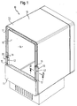
- FIG. 1 is a simplified schematic representation of a household refrigeration appliance 10 is shown with a partially shown, in the closed state door 11, which is thermally insulated in a conventional manner by foaming and which is provided at its free edges circumferentially with a magnetic seal 12.
- the door 11 is pivotally mounted on non-illustrated hinges on a vacuum-insulated refrigeration device housing 13, which receives a refrigeration equipment compartment 14 in itself.
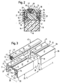
- the cold room 14 is lined by a stainless steel formed largely vacuum-tight inner lining 15, which is arranged at a distance also made of stainless steel sheet outer lining 16, at the door 11 facing edge portions retaining lugs 16.1 are provided.
- the door 11 facing edge portions of the inner panel 15 and the outer panel 16 are connected to a vacuum-tight from a thin-walled, poor heat-conducting material shaped, formed in cross-section U-shaped membrane 17.
- a thin-walled, poor heat-conducting material shaped, formed in cross-section U-shaped membrane 17 Through the membrane 17 is provided between the outer panel 16 and the inner panel 15 an evacuatable gap, which evacuatable Support material 18 such as open-cell polystyrene foam or the like for supporting the inner panel 15 and the outer panel 16 is filled.
- the membrane 17 On the outer side facing away from the support material 18, the membrane 17 is covered to protect its thin-walled base by a molded from hard tough, durable elastic polyethylene foam membrane cover 19 which has a bulk density between 70 and 100 kg per m 3 sufficient resistance to moisture diffusion, whereby the Membrane 17 is protected from condensation.
- the membrane cover 19 made of foamed material is provided to protect it in cross-section substantially U-profile-like protection profile 20, which according to a first embodiment (see Figure 2 and Figure 3) of two in cross-section substantially angularly shaped, constructed in mirror image Partial profiles composed of which a first partial profile 21 has an angle leg 22 and an angle leg 23 arranged perpendicular thereto, of which the latter is provided at its free end with a step-like recessed recess 24.
- the angle leg 23 has on its underside opposite the recess 24 a retaining wall 25 which projects back from the free end of the angle leg 22, with a holding opening 25.1 which runs parallel to the angle leg 22.
- Both the angle leg 22 and the angle leg 23 have at one of their free ends a step 27 and 28 which recesses stepwise relative to their outside, up to the beginning of which the retaining wall 25 extends.
- the protective profile 20 which is substantially U-shaped in cross-section, has a further partial profile 29 in addition to the partial profile 21, which is constructed in mirror image to the partial profile 21 and which, like this, forms a first angle leg 30 and a second one substantially perpendicularly arranged angle leg 31 has, which is provided at its free end as the angle leg 23 with a step-like recessed recess 32.
- a retaining wall 33 provided with a holding opening 33.1.
- the retaining wall 33 which springs back with its free end relative to the free end of the angle leg 30, extends at a parallel distance from the angle leg 30, whereby a retaining groove 34 is formed between it and the retaining wall 33.
- the angle legs 30 and 31 have at one of their free ends a section 35 or 36 which recesses stepwise relative to its outside, up to the beginning of which the retaining wall 33 and thus the retaining groove 34 extend.
- plug-in elements 37 and 38 are formed on the partial profile 29 and 21, respectively.
- each of the subdivided into longitudinal sections with the length L sub-profiles 21 and 29 are each provided with a plug receptacle 39 and 40, in which the plug-in elements 37 and 38 are inserted (as indicated by the arrow), whereby the individual Longitudinal sections of the sub-profiles 21 and 22 are joined together to form a continuous profile.
- the composed of individual lengths 1 to n sub-profiles 21 and 29 are fixed by means of their retaining groove 26 and 34 at the free end portions of the inner lining 15 and the outer panel 16 and thereto by a positive connection between the retaining lugs 16.1 and the holding openings 25.1 and 33.1 attached.
- the sub-profiles 21 and 29 form the U-profile-like protection profile 20.
- a gap 41 is formed between the free ends of their angle legs 23 and 31, which one through the recess 24 and the recess 32 in the assembled state
- Sub-profiles 21 and 29 formed receptacle is upstream.
- the gap 41 serves to secure a magnetic seal 42, which is equipped for this purpose with a sealing foot 43, which has a leading insertion bevel 44 and subsequently arranged undercuts 45.
- the sealing foot 43 is elastically connected to a hollow profile designed as a sealing head 46, which has a longitudinal direction of the magnetic seal 42 extending hollow chamber 47, in which a rod-shaped permanent magnet 48 is inserted.
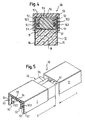
- a second embodiment of a protective profile 50 is shown, which is like the protective profile 20 in cross-section substantially U-shaped, but in contrast to this is not divided into sub-profiles.
- the protective profile 50 has arranged with a parallel distance to its U-profile legs 51 retaining walls 52 with holding openings 52.1, wherein the free end of the retaining walls 52 springs back relative to the free end of the U-profile legs. Due to the parallel spacing of the retaining walls 52 of the U-profile legs 51 a retaining groove 53 is formed between each of these and the retaining walls 52.
- the protective profile 50 produced, for example, made of plastic injection molding is provided at its base 54 with an insert, which is formed in the present case as a rod-shaped permanent magnet 55, which covers the outside of the base 54 opposite the free ends of the retaining walls 52 for its protection is.
- the protective profile 50 is like the protective profile 20 divided into individual longitudinal sections 1 to n with the length L, of which the over the corner regions of the refrigerator housing 13 away extending longitudinal sections are formed integrally continuously and of which two adjacent to each other longitudinal sections I and II via a Art plug connection are connected to each other.
- the longitudinal section I is provided at one of its free ends with a shoulder which recesses stepwise relative to its outer side, which serves as a plug element 56, while the longitudinal section II has a plug-in receptacle 57 arranged within the U-section space at its end section facing the longitudinal section I, in which the plug element 56 can be inserted in the direction of the arrow.
- the longitudinal sections 1 to n of the protective profile 50 are to facilitate the assembly individually based on their retaining grooves 53 at the free edges of the inner lining 15 and the outer panel 16 can be fixed and with their Holding openings 52.1 latched to the retaining lugs 16.1, whereby the assembled to the protective profile 50 on the basis of the plug-in elements 56 receiving receptacles 57 longitudinal sections at the free end portions of the inner lining 15 and the outer lining 16 are supported.
- the sharp-edged free edges of the inner panel 15 and the outer panel 16 and at the same time the shock-sensitive membrane cover 19 is covered protective.
Landscapes
- Engineering & Computer Science (AREA)
- Chemical & Material Sciences (AREA)
- Combustion & Propulsion (AREA)
- Physics & Mathematics (AREA)
- Mechanical Engineering (AREA)
- Thermal Sciences (AREA)
- General Engineering & Computer Science (AREA)
- Refrigerator Housings (AREA)
- Shielding Devices Or Components To Electric Or Magnetic Fields (AREA)
- Building Environments (AREA)
Claims (11)
- Paroi thermo-isolante telle que porte d'appareil frigorifique, enceinte d'appareil frigorifique ou similaire, avec un revêtement extérieur essentiellement étanche au vide lequel enferme, ensemble avec une membrane de liaison étanche au vide, immobilisée sur ses bords libres et formée d'un matériau mauvais conducteur de chaleur et un revêtement intérieur relié au niveau de ses bords libres de manière étanche au vide à ladite membrane de liaison, un creux apte à produire du vide et rempli de matériau de support apte à produire du vide, ladite membrane de liaison étant recouverte par un cache membrane formé d'un matériau mauvais conducteur de chaleur, caractérisée en ce que devant ledit cache membrane (19) est placé un profilé de protection (20, 50) recouvrant celui-ci et immobilisé sur le revêtement intérieur (15) et/ou le revêtement extérieur (16), qui est pourvu d'un pôle opposé magnétique (55) ou d'un joint magnétique (42).
- Paroi thermo-isolante selon la revendication 1, caractérisée en ce que le profilé de protection (20, 50) est réalisé essentiellement à la manière d'un profilé en U pourvu de moyens de fixation prévus sur ses deux branches (22, 30 ; 51) pour la fixation amovible sur le revêtement intérieur (15) et/ou le revêtement extérieur (16).
- Paroi thermo-isolante selon la revendication 2, caractérisée en ce que les moyens de fixation pour la fixation du profilé en U sont réalisés sous forme de rainure de fixation (26, 34 ; 53) laquelle est apte à être assemblée avec les bords libres du revêtement intérieur (15) et du revêtement extérieur (16).
- Paroi thermo-isolante selon l'une des revendications 2 à 3, caractérisée en ce que le profilé en U est pourvu sur sa base (23, 31 ; 54) reliant les branches (22, 30 ; 51) dudit pôle opposé magnétique (55) ou dudit joint magnétique (42).
- Paroi thermo-isolante selon la revendication 2 ou 4, caractérisée en ce que ledit pôle opposé magnétique (55) est disposé du côté des branches sur la base (54) du profilé en U.
- Paroi thermo-isolante selon l'une des revendications 2 à 4, caractérisée en ce que le profilé en U comprend sur sa base (23, 31) des moyens de fixation pour maintenir en place le joint magnétique (42).
- Paroi thermo-isolante selon l'une des revendications 1 à 6, caractérisée en ce que le profilé de protection (20) réalisé à la manière d'un profilé en U est formé de deux profilés en équerre (21, 29) dont chacun peut être immobilisé sur le revêtement intérieur (15) et/ou le revêtement extérieur (16).
- Paroi thermo-isolante selon la revendication 7, caractérisée en ce que les profilés en équerre (21, 29) avec leurs branches (22, 30) formant la base (23, 31) du profilé en U forment un espace (41) servant de moyen de fixation, dans lequel peuvent se fixer de manière amovible des moyens d'encliquetage (44, 45) prévus sur le joint magnétique (42).
- Paroi thermo-isolante selon la revendication 8, caractérisée en ce que chaque branche (22, 30) comporte à son extrémité tournée vers l'espace (41) un creux (24, 32) à gradin s'étendant dans le sens de l'espace, qui forme avec le creux contigu opposé (24, 32) de l'autre branche (21, 29) un logement pour la fixation du joint magnétique (42) dans le sens longitudinal du profilé en U.
- Paroi thermo-isolante selon l'une des revendications 2 à 9, caractérisée en ce que le profilé en U est divisé en différents tronçons longitudinaux (1 à n), lesquels peuvent être assemblés à la manière d'une connexion enfichable.
- Paroi thermo-isolante selon la revendication 10, caractérisée en ce que les tronçons longitudinaux (1 à n) du profilé en U sont réalisés au-delà des zones d'angle en une pièce de manière continue.
Applications Claiming Priority (3)
| Application Number | Priority Date | Filing Date | Title |
|---|---|---|---|
| DE19907182 | 1999-02-19 | ||
| DE19907182A DE19907182A1 (de) | 1999-02-19 | 1999-02-19 | Wärmeisolierende Wand |
| PCT/EP2000/001079 WO2000049352A1 (fr) | 1999-02-19 | 2000-02-10 | Paroi thermo-isolante |
Publications (2)
| Publication Number | Publication Date |
|---|---|
| EP1157246A1 EP1157246A1 (fr) | 2001-11-28 |
| EP1157246B1 true EP1157246B1 (fr) | 2006-06-14 |
Family
ID=7898178
Family Applications (1)
| Application Number | Title | Priority Date | Filing Date |
|---|---|---|---|
| EP00910665A Expired - Lifetime EP1157246B1 (fr) | 1999-02-19 | 2000-02-10 | Paroi thermo-isolante |
Country Status (8)
| Country | Link |
|---|---|
| US (1) | US6485122B2 (fr) |
| EP (1) | EP1157246B1 (fr) |
| JP (1) | JP2002537539A (fr) |
| AT (1) | ATE330192T1 (fr) |
| DE (2) | DE19907182A1 (fr) |
| ES (1) | ES2265915T3 (fr) |
| TR (1) | TR200101426T2 (fr) |
| WO (1) | WO2000049352A1 (fr) |
Cited By (1)
| Publication number | Priority date | Publication date | Assignee | Title |
|---|---|---|---|---|
| CN107850378A (zh) * | 2015-08-03 | 2018-03-27 | Lg电子株式会社 | 真空绝热体及冰箱 |
Families Citing this family (99)
| Publication number | Priority date | Publication date | Assignee | Title |
|---|---|---|---|---|
| DE19951532A1 (de) * | 1999-10-26 | 2001-05-03 | Bsh Bosch Siemens Hausgeraete | Kältegerät, wie Kühl- oder Gefrierschrank |
| ITMI20011868A1 (it) * | 2001-09-06 | 2003-03-06 | Whirlpool Co | Apparecchio refrigerante con isolamento sottovuoto |
| US6918341B1 (en) * | 2002-01-24 | 2005-07-19 | Metro Industries, Inc. | Support for securing cantilevered shelving to an insulated unit |
| EP1353135B1 (fr) * | 2002-04-08 | 2010-08-25 | Whirlpool Corporation | Réfrigérateur à vide isolant et procédé d'évacuation de la paroi étanche isolée |
| US7096640B1 (en) * | 2003-05-30 | 2006-08-29 | Traco | Thermal breaking system for construction materials and the like |
| US7752822B2 (en) * | 2003-12-09 | 2010-07-13 | Kysor Panel Systems | Composite framing member for use in an insulated panel for walk-in coolers and freezers and non-refrigerated enclosures |
| ITMI20040737A1 (it) * | 2004-04-14 | 2004-07-14 | Whirlpool Co | Apparecchio frigorifero e-o congelatore modulare |
| US20070039259A1 (en) * | 2005-06-08 | 2007-02-22 | Macdonald Douglas B | Connector strip for partition panel assembly |
| DE102005057143A1 (de) * | 2005-11-30 | 2007-06-06 | BSH Bosch und Siemens Hausgeräte GmbH | Kältegerät mit Isolationsleiste zum thermischen Entkoppeln der Seitenwände |
| US8112941B2 (en) * | 2007-05-16 | 2012-02-14 | Alcoa Commercial Windows Llc | Construction product having a moveable element with multi-functional thermal break |
| US7987633B2 (en) * | 2007-05-16 | 2011-08-02 | Alcoa Commercial Windows Llc | Construction product having a frame with multi-functional thermal break |
| DE202008005352U1 (de) * | 2008-04-17 | 2008-07-03 | BSH Bosch und Siemens Hausgeräte GmbH | Haushaltsstandgerät mit durch Befestigungsmittel verbundener Außenwand |
| AU2009250075A1 (en) * | 2008-05-23 | 2009-11-26 | Aktiebolaget Electrolux | Cold appliance |
| US8341920B2 (en) * | 2008-08-01 | 2013-01-01 | Everlast Doors Industries, Sa | Metal door |
| DE202009001784U1 (de) * | 2009-02-12 | 2009-04-16 | Gebhardt Transport- Und Lagersysteme Gmbh | Kühltransportbehälter |
| DE102010003458B4 (de) * | 2010-03-30 | 2016-12-15 | BSH Hausgeräte GmbH | Kältegerät, insbesondere Standkältegerät |
| KR101147779B1 (ko) * | 2010-10-28 | 2012-05-25 | 엘지전자 주식회사 | 진공공간부를 구비하는 냉장고 |
| KR101227516B1 (ko) | 2010-10-28 | 2013-01-31 | 엘지전자 주식회사 | 진공공간부를 구비하는 냉장고 |
| KR101898487B1 (ko) | 2010-10-28 | 2018-10-04 | 엘지전자 주식회사 | 진공공간부를 구비하는 냉장고 |
| ITRE20110010A1 (it) * | 2011-02-24 | 2012-08-25 | Guiducci Alessandro E C S A S | Telaio per l'apertura d'accesso di armadi frigoriferi |
| CN103162496B (zh) * | 2011-12-16 | 2017-05-17 | 博西华电器(江苏)有限公司 | 制冷器具 |
| US9221210B2 (en) | 2012-04-11 | 2015-12-29 | Whirlpool Corporation | Method to create vacuum insulated cabinets for refrigerators |
| US9140481B2 (en) | 2012-04-02 | 2015-09-22 | Whirlpool Corporation | Folded vacuum insulated structure |
| US9062480B2 (en) | 2012-08-14 | 2015-06-23 | Whirlpool Corporation | Gasket and flange design on a refrigerator for better energy efficiency |
| KR101565420B1 (ko) | 2012-12-13 | 2015-11-05 | 엘지전자 주식회사 | 진공공간부를 구비하는 냉장고 |
| CA2845638C (fr) * | 2013-03-15 | 2016-06-07 | Alcoa Inc. | Procede pour integrer des barrieres thermiques dans des extrusions tubulaires a l'aide de bagues de maintien |
| US10052819B2 (en) | 2014-02-24 | 2018-08-21 | Whirlpool Corporation | Vacuum packaged 3D vacuum insulated door structure and method therefor using a tooling fixture |
| US9476633B2 (en) | 2015-03-02 | 2016-10-25 | Whirlpool Corporation | 3D vacuum panel and a folding approach to create the 3D vacuum panel from a 2D vacuum panel of non-uniform thickness |
| US10161669B2 (en) | 2015-03-05 | 2018-12-25 | Whirlpool Corporation | Attachment arrangement for vacuum insulated door |
| US9897370B2 (en) | 2015-03-11 | 2018-02-20 | Whirlpool Corporation | Self-contained pantry box system for insertion into an appliance |
| US9441779B1 (en) | 2015-07-01 | 2016-09-13 | Whirlpool Corporation | Split hybrid insulation structure for an appliance |
| KR20170016188A (ko) | 2015-08-03 | 2017-02-13 | 엘지전자 주식회사 | 진공단열체 및 냉장고 |
| KR102498210B1 (ko) | 2015-08-03 | 2023-02-09 | 엘지전자 주식회사 | 진공단열체 및 냉장고 |
| KR102529853B1 (ko) | 2015-08-03 | 2023-05-08 | 엘지전자 주식회사 | 진공단열체, 진공단열체의 제조방법, 다공성물질패키지, 및 냉장고 |
| KR102456642B1 (ko) * | 2015-08-03 | 2022-10-19 | 엘지전자 주식회사 | 진공단열체 및 냉장고 |
| KR102497139B1 (ko) * | 2015-08-03 | 2023-02-07 | 엘지전자 주식회사 | 진공단열체 |
| KR102447245B1 (ko) | 2015-08-03 | 2022-09-27 | 엘지전자 주식회사 | 진공단열체 및 냉장고 |
| KR102525551B1 (ko) | 2015-08-03 | 2023-04-25 | 엘지전자 주식회사 | 진공단열체 및 냉장고 |
| KR102442973B1 (ko) * | 2015-08-03 | 2022-09-14 | 엘지전자 주식회사 | 진공단열체 및 냉장고 |
| KR102502160B1 (ko) | 2015-08-03 | 2023-02-21 | 엘지전자 주식회사 | 진공단열체 및 냉장고 |
| KR102529852B1 (ko) | 2015-08-03 | 2023-05-08 | 엘지전자 주식회사 | 진공단열체 및 냉장고 |
| WO2017023094A1 (fr) | 2015-08-03 | 2017-02-09 | Lg Electronics Inc. | Corps adiabatique sous vide et réfrigérateur |
| KR102525550B1 (ko) | 2015-08-03 | 2023-04-25 | 엘지전자 주식회사 | 진공단열체 및 냉장고 |
| KR102466470B1 (ko) | 2015-08-04 | 2022-11-11 | 엘지전자 주식회사 | 진공단열체 및 냉장고 |
| US10222116B2 (en) | 2015-12-08 | 2019-03-05 | Whirlpool Corporation | Method and apparatus for forming a vacuum insulated structure for an appliance having a pressing mechanism incorporated within an insulation delivery system |
| US12508751B2 (en) | 2015-12-08 | 2025-12-30 | Whirlpool Corporation | Insulation compaction device and method for forming an insulated structure for an appliance |
| US11052579B2 (en) | 2015-12-08 | 2021-07-06 | Whirlpool Corporation | Method for preparing a densified insulation material for use in appliance insulated structure |
| US10041724B2 (en) | 2015-12-08 | 2018-08-07 | Whirlpool Corporation | Methods for dispensing and compacting insulation materials into a vacuum sealed structure |
| US10422573B2 (en) | 2015-12-08 | 2019-09-24 | Whirlpool Corporation | Insulation structure for an appliance having a uniformly mixed multi-component insulation material, and a method for even distribution of material combinations therein |
| US10429125B2 (en) | 2015-12-08 | 2019-10-01 | Whirlpool Corporation | Insulation structure for an appliance having a uniformly mixed multi-component insulation material, and a method for even distribution of material combinations therein |
| US11994336B2 (en) | 2015-12-09 | 2024-05-28 | Whirlpool Corporation | Vacuum insulated structure with thermal bridge breaker with heat loop |
| US10808987B2 (en) | 2015-12-09 | 2020-10-20 | Whirlpool Corporation | Vacuum insulation structures with multiple insulators |
| US20240271859A1 (en) * | 2015-12-09 | 2024-08-15 | Whirlpool Corporation | Vacuum insulated structure with thermal bridge breaker with heat loop |
| US10422569B2 (en) | 2015-12-21 | 2019-09-24 | Whirlpool Corporation | Vacuum insulated door construction |
| US10018406B2 (en) | 2015-12-28 | 2018-07-10 | Whirlpool Corporation | Multi-layer gas barrier materials for vacuum insulated structure |
| US10610985B2 (en) | 2015-12-28 | 2020-04-07 | Whirlpool Corporation | Multilayer barrier materials with PVD or plasma coating for vacuum insulated structure |
| US10807298B2 (en) | 2015-12-29 | 2020-10-20 | Whirlpool Corporation | Molded gas barrier parts for vacuum insulated structure |
| US11247369B2 (en) | 2015-12-30 | 2022-02-15 | Whirlpool Corporation | Method of fabricating 3D vacuum insulated refrigerator structure having core material |
| US10712080B2 (en) | 2016-04-15 | 2020-07-14 | Whirlpool Corporation | Vacuum insulated refrigerator cabinet |
| EP3443284B1 (fr) | 2016-04-15 | 2020-11-18 | Whirlpool Corporation | Structure de réfrigérateur à isolation sous vide, dotée de caractéristiques tridimensionnelles |
| US11320193B2 (en) * | 2016-07-26 | 2022-05-03 | Whirlpool Corporation | Vacuum insulated structure trim breaker |
| WO2018022009A1 (fr) | 2016-07-26 | 2018-02-01 | Whirlpool Corporation | Coupe-pont thermique et caractéristiques d'étanchéité dans une structure à isolation sous vide à paroi mince |
| WO2018034665A1 (fr) | 2016-08-18 | 2018-02-22 | Whirlpool Corporation | Compartiment de machine pour une structure isolée sous vide |
| EP3507554B1 (fr) * | 2016-08-30 | 2023-08-02 | Whirlpool Corporation | Procédé pour la fabrication d'un disjoncteur à pont thermique en plastique surmoulé scellé hermétiquement avec doublure et enveloppe pour une structure isolée sous vide |
| EP3516285B1 (fr) | 2016-09-26 | 2022-05-18 | Whirlpool Corporation | Appareil comprenant une structure isolée sous vide |
| EP3519746B1 (fr) | 2016-10-03 | 2022-10-26 | Whirlpool Corporation | Système d'encapsulation pour relier un élément de rupture de pont thermique à un revêtement métallique |
| EP3526531A4 (fr) | 2016-10-11 | 2020-06-17 | Whirlpool Corporation | Armoire structurale pour appareil incorporant des boîtes métalliques unitaires |
| US10352613B2 (en) | 2016-12-05 | 2019-07-16 | Whirlpool Corporation | Pigmented monolayer liner for appliances and methods of making the same |
| KR102737516B1 (ko) * | 2016-12-23 | 2024-12-04 | 삼성전자주식회사 | 냉장고 |
| WO2018151705A1 (fr) | 2017-02-14 | 2018-08-23 | Whirlpool Corporation | Système d'encapsulation multicouche pour scellement étanche d'armoires isolées sous vide |
| KR102459784B1 (ko) | 2017-08-01 | 2022-10-28 | 엘지전자 주식회사 | 진공단열체 및 냉장고 |
| KR102449175B1 (ko) | 2017-08-01 | 2022-09-29 | 엘지전자 주식회사 | 진공단열체 및 냉장고 |
| KR102449177B1 (ko) | 2017-08-01 | 2022-09-29 | 엘지전자 주식회사 | 진공단열체 및 냉장고 |
| KR102427466B1 (ko) | 2017-08-01 | 2022-08-01 | 엘지전자 주식회사 | 차량, 차량용 냉장고, 및 차량용 냉장고의 제어방법 |
| KR102529116B1 (ko) * | 2017-08-01 | 2023-05-08 | 엘지전자 주식회사 | 진공단열체, 진공단열체의 제작방법, 및 그 진공단열체로 단열하는 냉온장고 |
| KR102459786B1 (ko) | 2017-08-16 | 2022-10-28 | 엘지전자 주식회사 | 진공단열체 및 냉장고 |
| KR102511095B1 (ko) | 2017-12-13 | 2023-03-16 | 엘지전자 주식회사 | 진공단열체 및 냉장고 |
| KR102466446B1 (ko) | 2017-12-13 | 2022-11-11 | 엘지전자 주식회사 | 진공단열체 및 냉장고 |
| KR102568737B1 (ko) | 2017-12-13 | 2023-08-21 | 엘지전자 주식회사 | 진공단열체 및 냉장고 |
| KR102466448B1 (ko) * | 2017-12-13 | 2022-11-11 | 엘지전자 주식회사 | 진공단열체 및 냉장고 |
| KR102530909B1 (ko) | 2017-12-13 | 2023-05-11 | 엘지전자 주식회사 | 진공단열체 및 냉장고 |
| US10907888B2 (en) | 2018-06-25 | 2021-02-02 | Whirlpool Corporation | Hybrid pigmented hot stitched color liner system |
| KR102617454B1 (ko) * | 2018-06-27 | 2023-12-26 | 엘지전자 주식회사 | 진공단열체, 및 냉장고 |
| US10697699B2 (en) * | 2018-11-05 | 2020-06-30 | Whirlpool Corporation | Cabinet assembly of an appliance |
| US10801773B2 (en) * | 2018-12-29 | 2020-10-13 | Whirlpool Corporation | Metallic trim breaker for a refrigerating appliance having a thermal bridge geometry |
| US10907891B2 (en) * | 2019-02-18 | 2021-02-02 | Whirlpool Corporation | Trim breaker for a structural cabinet that incorporates a structural glass contact surface |
| US11320194B2 (en) | 2019-04-30 | 2022-05-03 | Whirlpool Corporation | Barrier layer for insulated structures |
| DE102019209959A1 (de) * | 2019-07-05 | 2021-01-07 | BSH Hausgeräte GmbH | Haushaltsgerätevorrichtung |
| KR102896110B1 (ko) * | 2019-07-09 | 2025-12-05 | 엘지전자 주식회사 | 진공단열체 및 냉장고 |
| KR20210006717A (ko) * | 2019-07-09 | 2021-01-19 | 엘지전자 주식회사 | 진공단열모듈, 및 냉장고 |
| KR102896112B1 (ko) * | 2019-07-09 | 2025-12-05 | 엘지전자 주식회사 | 진공단열체 및 냉장고 |
| US11346596B2 (en) | 2019-12-30 | 2022-05-31 | Whirpool Corporation | Trim breaker for an insulated appliance |
| US10914514B1 (en) | 2020-01-17 | 2021-02-09 | Whirlpool Corporation | Illuminated trim assembly for appliance |
| EP3926269A1 (fr) * | 2020-06-15 | 2021-12-22 | Horeca Engineering B.V. | Réfrigérateur |
| US12070924B2 (en) | 2020-07-27 | 2024-08-27 | Whirlpool Corporation | Appliance liner having natural fibers |
| US11709013B2 (en) | 2021-01-20 | 2023-07-25 | Whirlpool Corporation | Appliance trim breaker |
| US11340008B1 (en) | 2021-01-20 | 2022-05-24 | Whirlpool Corporation | Appliance trim breaker assembly |
| US11858235B2 (en) | 2021-09-16 | 2024-01-02 | Whirlpool Corporation | Trim breaker having metallic insert for decreased gas permeation |
| JP7833688B2 (ja) * | 2023-06-19 | 2026-03-23 | パナソニックIpマネジメント株式会社 | 貯蔵庫 |
Family Cites Families (13)
| Publication number | Priority date | Publication date | Assignee | Title |
|---|---|---|---|---|
| US2518673A (en) * | 1945-05-14 | 1950-08-15 | Seeger Refrigerator Co | Breaker strip construction |
| US2644605A (en) * | 1950-02-28 | 1953-07-07 | Int Harvester Co | Breaker strip construction |
| US2809764A (en) * | 1955-12-27 | 1957-10-15 | Whirlpool Seeger Corp | Duo-plastic molded breaker strip |
| US2855636A (en) * | 1957-02-18 | 1958-10-14 | Ben Hur Mfg Company | Edge dovetail insulated wall construction |
| DE1105893B (de) * | 1959-07-11 | 1961-05-04 | Bosch Gmbh Robert | Kuehl-, insbesondere Gefrierschrank mit einem Heizwiderstand zur Erwaermung des Tuerrahmens und mit einer Anzeigelampe |
| US3353321A (en) * | 1965-09-15 | 1967-11-21 | Star Metal Corp | Thermal breaker strip |
| US3380615A (en) * | 1965-11-17 | 1968-04-30 | Westinghouse Electric Corp | Refrigeration apparatus cabinet construction |
| IT1000250B (it) * | 1973-12-07 | 1976-03-30 | Ire Ind Ruinite | Cornice per mobile frigorifero |
| US4330310A (en) * | 1980-08-22 | 1982-05-18 | Whirlpool Corporation | Plastic mullion rail assembly for refrigerator |
| NL8401588A (nl) * | 1984-05-17 | 1985-12-16 | Ie Pe Ge B V | Raamwerk van tochtband voor meubelstukken, zoals koelkasten en dergelijke. |
| US4732432A (en) * | 1986-12-29 | 1988-03-22 | Whirlpool Corporation | Breaker strip for a refrigerator cabinet |
| DE4342948A1 (de) | 1993-12-16 | 1995-06-22 | Licentia Gmbh | Wärmeisolationselement |
| DE19745825A1 (de) * | 1997-10-16 | 1999-04-22 | Bosch Siemens Hausgeraete | Wärmeisolierende Wandung |
-
1999
- 1999-02-19 DE DE19907182A patent/DE19907182A1/de not_active Withdrawn
-
2000
- 2000-02-10 JP JP2000600048A patent/JP2002537539A/ja active Pending
- 2000-02-10 EP EP00910665A patent/EP1157246B1/fr not_active Expired - Lifetime
- 2000-02-10 DE DE50012984T patent/DE50012984D1/de not_active Expired - Lifetime
- 2000-02-10 ES ES00910665T patent/ES2265915T3/es not_active Expired - Lifetime
- 2000-02-10 AT AT00910665T patent/ATE330192T1/de not_active IP Right Cessation
- 2000-02-10 TR TR2001/01426T patent/TR200101426T2/xx unknown
- 2000-02-10 WO PCT/EP2000/001079 patent/WO2000049352A1/fr not_active Ceased
-
2001
- 2001-08-20 US US09/933,046 patent/US6485122B2/en not_active Expired - Lifetime
Cited By (2)
| Publication number | Priority date | Publication date | Assignee | Title |
|---|---|---|---|---|
| CN107850378A (zh) * | 2015-08-03 | 2018-03-27 | Lg电子株式会社 | 真空绝热体及冰箱 |
| CN107850378B (zh) * | 2015-08-03 | 2021-07-16 | Lg电子株式会社 | 真空绝热体及冰箱 |
Also Published As
| Publication number | Publication date |
|---|---|
| JP2002537539A (ja) | 2002-11-05 |
| DE50012984D1 (de) | 2006-07-27 |
| ES2265915T3 (es) | 2007-03-01 |
| EP1157246A1 (fr) | 2001-11-28 |
| WO2000049352A1 (fr) | 2000-08-24 |
| DE19907182A1 (de) | 2000-08-24 |
| ATE330192T1 (de) | 2006-07-15 |
| US20020041134A1 (en) | 2002-04-11 |
| US6485122B2 (en) | 2002-11-26 |
| TR200101426T2 (tr) | 2001-12-21 |
Similar Documents
| Publication | Publication Date | Title |
|---|---|---|
| EP1157246B1 (fr) | Paroi thermo-isolante | |
| DE10355137A1 (de) | Kältegerätegehäuse | |
| DE19948361A1 (de) | Kältegerät | |
| DE4334761A1 (de) | Haushaltsgerät zum Einbau in eine Möbelnische einer Küchenzeile oder dergleichen | |
| EP2464926B1 (fr) | Balconnet pour un appareil de froid | |
| DE4342948A1 (de) | Wärmeisolationselement | |
| DE102004014464A1 (de) | Befestigungsanordnung und Verfahren zur Befestigung von Elementen an der Innenverkleidung von Kühl- und/oder Gefriergeräten und Verfahren zur Herstellung einer solchen Befestigungsanordnung | |
| DE102019205875A1 (de) | Haushaltskältegerät und Verfahren zum Herstellen eines Haushaltskältegerätes | |
| EP2499445A2 (fr) | Appareil frigorifique muni d'un balconnet de porte et d'un dispositif d'arrêt à montage flottant | |
| EP1023563B1 (fr) | Paroi calorifuge | |
| DE102017205089A1 (de) | Haushaltskältegerät mit einer Innenverkleidung mit mehreren separaten Verkleidungswänden sowie Verfahren zum Herstellen eines Haushaltskältegeräts | |
| DE102008019261A1 (de) | Haushalts-Kältegerät mit mindestens einem Abstellbehältnis | |
| EP0582781B1 (fr) | Appareil frigorifique comprenant des éléments porteurs pour étagères à introduire dans l'espace intérieur de l'appareil | |
| WO1999020965A1 (fr) | Paroi calorifuge | |
| EP2258994A2 (fr) | Appareil de refroidissement ménager doté d'au moins un rail de renforcement | |
| DE19856093A1 (de) | Kältegerätetür | |
| EP0387494A2 (fr) | Tiroir de soubassement | |
| DE19907147A1 (de) | Kältegerätetür | |
| WO2012065850A2 (fr) | Porte d'appareil de froid | |
| EP1110045B1 (fr) | Porte de refrigerateur ou de congelateur avec un joint | |
| EP0582780A1 (fr) | Elément porteur pour plancher intermédiaire à introduire dans un espace intérieur d'un meuble | |
| DE3503552A1 (de) | Kaeltemaschine, vorzugsweise kuehlschrank | |
| EP3546860B1 (fr) | Appareil électroménager doté d'un contour d'ajustement formé sur un élément mural | |
| DE102014206948A1 (de) | Haushaltskältegerät | |
| EP0886749B1 (fr) | Contenant muni d'une zone limite thermique continue |
Legal Events
| Date | Code | Title | Description |
|---|---|---|---|
| PUAI | Public reference made under article 153(3) epc to a published international application that has entered the european phase |
Free format text: ORIGINAL CODE: 0009012 |
|
| 17P | Request for examination filed |
Effective date: 20010919 |
|
| AK | Designated contracting states |
Kind code of ref document: A1 Designated state(s): AT BE CH CY DE DK ES FI FR GB GR IE IT LI LU MC NL PT SE |
|
| AX | Request for extension of the european patent |
Free format text: SI PAYMENT 20010919 |
|
| RAP1 | Party data changed (applicant data changed or rights of an application transferred) |
Owner name: BSH BOSCH UND SIEMENS HAUSGERAETE GMBH |
|
| 17Q | First examination report despatched |
Effective date: 20040415 |
|
| GRAP | Despatch of communication of intention to grant a patent |
Free format text: ORIGINAL CODE: EPIDOSNIGR1 |
|
| GRAS | Grant fee paid |
Free format text: ORIGINAL CODE: EPIDOSNIGR3 |
|
| GRAA | (expected) grant |
Free format text: ORIGINAL CODE: 0009210 |
|
| AK | Designated contracting states |
Kind code of ref document: B1 Designated state(s): AT BE CH CY DE DK ES FI FR GB GR IE IT LI LU MC NL PT SE |
|
| AX | Request for extension of the european patent |
Extension state: SI |
|
| PG25 | Lapsed in a contracting state [announced via postgrant information from national office to epo] |
Ref country code: IT Free format text: LAPSE BECAUSE OF FAILURE TO SUBMIT A TRANSLATION OF THE DESCRIPTION OR TO PAY THE FEE WITHIN THE PRESCRIBED TIME-LIMIT;WARNING: LAPSES OF ITALIAN PATENTS WITH EFFECTIVE DATE BEFORE 2007 MAY HAVE OCCURRED AT ANY TIME BEFORE 2007. THE CORRECT EFFECTIVE DATE MAY BE DIFFERENT FROM THE ONE RECORDED. Effective date: 20060614 Ref country code: FI Free format text: LAPSE BECAUSE OF FAILURE TO SUBMIT A TRANSLATION OF THE DESCRIPTION OR TO PAY THE FEE WITHIN THE PRESCRIBED TIME-LIMIT Effective date: 20060614 Ref country code: IE Free format text: LAPSE BECAUSE OF FAILURE TO SUBMIT A TRANSLATION OF THE DESCRIPTION OR TO PAY THE FEE WITHIN THE PRESCRIBED TIME-LIMIT Effective date: 20060614 Ref country code: NL Free format text: LAPSE BECAUSE OF FAILURE TO SUBMIT A TRANSLATION OF THE DESCRIPTION OR TO PAY THE FEE WITHIN THE PRESCRIBED TIME-LIMIT Effective date: 20060614 |
|
| REG | Reference to a national code |
Ref country code: GB Ref legal event code: FG4D Free format text: NOT ENGLISH |
|
| REG | Reference to a national code |
Ref country code: CH Ref legal event code: EP |
|
| GBT | Gb: translation of ep patent filed (gb section 77(6)(a)/1977) |
Effective date: 20060620 |
|
| REG | Reference to a national code |
Ref country code: IE Ref legal event code: FG4D Free format text: LANGUAGE OF EP DOCUMENT: GERMAN |
|
| REF | Corresponds to: |
Ref document number: 50012984 Country of ref document: DE Date of ref document: 20060727 Kind code of ref document: P |
|
| PG25 | Lapsed in a contracting state [announced via postgrant information from national office to epo] |
Ref country code: DK Free format text: LAPSE BECAUSE OF FAILURE TO SUBMIT A TRANSLATION OF THE DESCRIPTION OR TO PAY THE FEE WITHIN THE PRESCRIBED TIME-LIMIT Effective date: 20060914 Ref country code: SE Free format text: LAPSE BECAUSE OF FAILURE TO SUBMIT A TRANSLATION OF THE DESCRIPTION OR TO PAY THE FEE WITHIN THE PRESCRIBED TIME-LIMIT Effective date: 20060914 |
|
| PG25 | Lapsed in a contracting state [announced via postgrant information from national office to epo] |
Ref country code: PT Free format text: LAPSE BECAUSE OF FAILURE TO SUBMIT A TRANSLATION OF THE DESCRIPTION OR TO PAY THE FEE WITHIN THE PRESCRIBED TIME-LIMIT Effective date: 20061114 |
|
| NLV1 | Nl: lapsed or annulled due to failure to fulfill the requirements of art. 29p and 29m of the patents act | ||
| REG | Reference to a national code |
Ref country code: IE Ref legal event code: FD4D |
|
| ET | Fr: translation filed | ||
| PG25 | Lapsed in a contracting state [announced via postgrant information from national office to epo] |
Ref country code: LI Free format text: LAPSE BECAUSE OF NON-PAYMENT OF DUE FEES Effective date: 20070228 Ref country code: CH Free format text: LAPSE BECAUSE OF NON-PAYMENT OF DUE FEES Effective date: 20070228 Ref country code: MC Free format text: LAPSE BECAUSE OF NON-PAYMENT OF DUE FEES Effective date: 20070228 |
|
| REG | Reference to a national code |
Ref country code: ES Ref legal event code: FG2A Ref document number: 2265915 Country of ref document: ES Kind code of ref document: T3 |
|
| PLBE | No opposition filed within time limit |
Free format text: ORIGINAL CODE: 0009261 |
|
| STAA | Information on the status of an ep patent application or granted ep patent |
Free format text: STATUS: NO OPPOSITION FILED WITHIN TIME LIMIT |
|
| 26N | No opposition filed |
Effective date: 20070315 |
|
| REG | Reference to a national code |
Ref country code: CH Ref legal event code: PL |
|
| BERE | Be: lapsed |
Owner name: BSH BOSCH UND SIEMENS HAUSGERATE G.M.B.H. Effective date: 20070228 |
|
| PG25 | Lapsed in a contracting state [announced via postgrant information from national office to epo] |
Ref country code: BE Free format text: LAPSE BECAUSE OF NON-PAYMENT OF DUE FEES Effective date: 20070228 |
|
| PG25 | Lapsed in a contracting state [announced via postgrant information from national office to epo] |
Ref country code: GR Free format text: LAPSE BECAUSE OF FAILURE TO SUBMIT A TRANSLATION OF THE DESCRIPTION OR TO PAY THE FEE WITHIN THE PRESCRIBED TIME-LIMIT Effective date: 20060915 |
|
| PG25 | Lapsed in a contracting state [announced via postgrant information from national office to epo] |
Ref country code: AT Free format text: LAPSE BECAUSE OF NON-PAYMENT OF DUE FEES Effective date: 20070210 |
|
| PG25 | Lapsed in a contracting state [announced via postgrant information from national office to epo] |
Ref country code: LU Free format text: LAPSE BECAUSE OF NON-PAYMENT OF DUE FEES Effective date: 20070210 Ref country code: CY Free format text: LAPSE BECAUSE OF FAILURE TO SUBMIT A TRANSLATION OF THE DESCRIPTION OR TO PAY THE FEE WITHIN THE PRESCRIBED TIME-LIMIT Effective date: 20060614 |
|
| PGFP | Annual fee paid to national office [announced via postgrant information from national office to epo] |
Ref country code: DE Payment date: 20130228 Year of fee payment: 14 |
|
| PGFP | Annual fee paid to national office [announced via postgrant information from national office to epo] |
Ref country code: IT Payment date: 20140224 Year of fee payment: 15 Ref country code: ES Payment date: 20140220 Year of fee payment: 15 Ref country code: FR Payment date: 20140218 Year of fee payment: 15 |
|
| PGFP | Annual fee paid to national office [announced via postgrant information from national office to epo] |
Ref country code: GB Payment date: 20140220 Year of fee payment: 15 |
|
| REG | Reference to a national code |
Ref country code: DE Ref legal event code: R119 Ref document number: 50012984 Country of ref document: DE |
|
| REG | Reference to a national code |
Ref country code: DE Ref legal event code: R119 Ref document number: 50012984 Country of ref document: DE Effective date: 20140902 |
|
| PG25 | Lapsed in a contracting state [announced via postgrant information from national office to epo] |
Ref country code: DE Free format text: LAPSE BECAUSE OF NON-PAYMENT OF DUE FEES Effective date: 20140902 |
|
| GBPC | Gb: european patent ceased through non-payment of renewal fee |
Effective date: 20150210 |
|
| REG | Reference to a national code |
Ref country code: FR Ref legal event code: ST Effective date: 20151030 |
|
| PG25 | Lapsed in a contracting state [announced via postgrant information from national office to epo] |
Ref country code: IT Free format text: LAPSE BECAUSE OF NON-PAYMENT OF DUE FEES Effective date: 20150210 |
|
| PG25 | Lapsed in a contracting state [announced via postgrant information from national office to epo] |
Ref country code: GB Free format text: LAPSE BECAUSE OF NON-PAYMENT OF DUE FEES Effective date: 20150210 |
|
| PG25 | Lapsed in a contracting state [announced via postgrant information from national office to epo] |
Ref country code: FR Free format text: LAPSE BECAUSE OF NON-PAYMENT OF DUE FEES Effective date: 20150302 |
|
| REG | Reference to a national code |
Ref country code: ES Ref legal event code: FD2A Effective date: 20160329 |
|
| PG25 | Lapsed in a contracting state [announced via postgrant information from national office to epo] |
Ref country code: ES Free format text: LAPSE BECAUSE OF NON-PAYMENT OF DUE FEES Effective date: 20150211 |