EP1157746B1 - Segmentierter, stapelbarer Düsenkopf - Google Patents
Segmentierter, stapelbarer Düsenkopf Download PDFInfo
- Publication number
- EP1157746B1 EP1157746B1 EP20010109639 EP01109639A EP1157746B1 EP 1157746 B1 EP1157746 B1 EP 1157746B1 EP 20010109639 EP20010109639 EP 20010109639 EP 01109639 A EP01109639 A EP 01109639A EP 1157746 B1 EP1157746 B1 EP 1157746B1
- Authority
- EP
- European Patent Office
- Prior art keywords
- service block
- assemblage
- fluid dispensing
- block
- dispensing head
- Prior art date
- Legal status (The legal status is an assumption and is not a legal conclusion. Google has not performed a legal analysis and makes no representation as to the accuracy of the status listed.)
- Expired - Lifetime
Links
- 239000000463 material Substances 0.000 claims description 20
- 239000004831 Hot glue Substances 0.000 claims description 13
- 230000037431 insertion Effects 0.000 claims 1
- 238000003780 insertion Methods 0.000 claims 1
- 239000012530 fluid Substances 0.000 description 86
- 230000000712 assembly Effects 0.000 description 19
- 238000000429 assembly Methods 0.000 description 19
- 230000008021 deposition Effects 0.000 description 16
- 239000000853 adhesive Substances 0.000 description 12
- 230000001070 adhesive effect Effects 0.000 description 12
- 230000000694 effects Effects 0.000 description 6
- 239000012943 hotmelt Substances 0.000 description 6
- 238000004519 manufacturing process Methods 0.000 description 4
- 230000007246 mechanism Effects 0.000 description 3
- 238000012986 modification Methods 0.000 description 2
- 230000004048 modification Effects 0.000 description 2
- 229920000642 polymer Polymers 0.000 description 2
- 230000004323 axial length Effects 0.000 description 1
- 230000008859 change Effects 0.000 description 1
- 239000002131 composite material Substances 0.000 description 1
- 239000008341 cosmetic lotion Substances 0.000 description 1
- -1 for example Substances 0.000 description 1
- 238000010438 heat treatment Methods 0.000 description 1
- 238000010348 incorporation Methods 0.000 description 1
- 239000000155 melt Substances 0.000 description 1
- 238000000034 method Methods 0.000 description 1
- 239000002245 particle Substances 0.000 description 1
- 230000008569 process Effects 0.000 description 1
- 239000000758 substrate Substances 0.000 description 1
Images
Classifications
-
- F—MECHANICAL ENGINEERING; LIGHTING; HEATING; WEAPONS; BLASTING
- F16—ENGINEERING ELEMENTS AND UNITS; GENERAL MEASURES FOR PRODUCING AND MAINTAINING EFFECTIVE FUNCTIONING OF MACHINES OR INSTALLATIONS; THERMAL INSULATION IN GENERAL
- F16K—VALVES; TAPS; COCKS; ACTUATING-FLOATS; DEVICES FOR VENTING OR AERATING
- F16K27/00—Construction of housing; Use of materials therefor
- F16K27/003—Housing formed from a plurality of the same valve elements
-
- B—PERFORMING OPERATIONS; TRANSPORTING
- B05—SPRAYING OR ATOMISING IN GENERAL; APPLYING FLUENT MATERIALS TO SURFACES, IN GENERAL
- B05C—APPARATUS FOR APPLYING FLUENT MATERIALS TO SURFACES, IN GENERAL
- B05C5/00—Apparatus in which liquid or other fluent material is projected, poured or allowed to flow on to the surface of the work
- B05C5/02—Apparatus in which liquid or other fluent material is projected, poured or allowed to flow on to the surface of the work the liquid or other fluent material being discharged through an outlet orifice by pressure, e.g. from an outlet device in contact or almost in contact, with the work
- B05C5/027—Coating heads with several outlets, e.g. aligned transversally to the moving direction of a web to be coated
- B05C5/0275—Coating heads with several outlets, e.g. aligned transversally to the moving direction of a web to be coated flow controlled, e.g. by a valve
- B05C5/0279—Coating heads with several outlets, e.g. aligned transversally to the moving direction of a web to be coated flow controlled, e.g. by a valve independently, e.g. individually, flow controlled
-
- Y—GENERAL TAGGING OF NEW TECHNOLOGICAL DEVELOPMENTS; GENERAL TAGGING OF CROSS-SECTIONAL TECHNOLOGIES SPANNING OVER SEVERAL SECTIONS OF THE IPC; TECHNICAL SUBJECTS COVERED BY FORMER USPC CROSS-REFERENCE ART COLLECTIONS [XRACs] AND DIGESTS
- Y10—TECHNICAL SUBJECTS COVERED BY FORMER USPC
- Y10T—TECHNICAL SUBJECTS COVERED BY FORMER US CLASSIFICATION
- Y10T137/00—Fluid handling
- Y10T137/8593—Systems
- Y10T137/877—With flow control means for branched passages
- Y10T137/87885—Sectional block structure
Definitions
- the present invention relates generally to fluid dispensing head assemblies, and more particularly to a new and improved fluid dispensing head segment or modular unit assembly which enables a plurality of fluid dispensing head segment or modular unit assemblies to be secured together so as to in effect customize the fabrication of a composite fluid dispensing head assembly such that the resulting assembly is optimally sized so as to be especially adapted for particularly desired or required customer applications.
- such other fluid dispensing head assemblies must in effect be customized or fabricated in a custom-made manner so as to in fact comprise a greater number of dispensing valves whereby such customized or custom-made fluid dispensing head assemblies would then be suitable for accomplishing the desired dispensing or deposition operations.
- the customized or custom-made fabrication of such other fluid dispensing head assemblies is quite time-consuming, whereby production of such other fluid dispensing head assemblies requires a considerable amount of time to achieve with the result that customer orders unfortunately require a considerable amount of time to fill.
- fluid dispensing head assemblies of predetermined sizes can in effect be rapidly fabricated or manufactured in order to readily meet customer's requirements for such predeterminedly sized fluid dispensing head assemblies without the need for customizing or custom-making such assemblies as original single integral assemblies having the desired or required sized dimensions.
- WO 99/67027 A shows a device for application of a unit system comprising units of at least two hollow members for different components.
- the hollow members can either have a common nozzle plate as shown in fig. 1- 3 of WO 99/67027 A or can be moved to change the sideway distance between two members.
- This document does not show a modular unit for connection with another modular unit having a service block and a predetermined number of dispensing valves mounted upon the service block. No modular concept is described in this document.
- WO 99/46057 discloses a segmented die assembly comprising a plurality of side-by-side and separate units. Each unit includes a manifold segment and a die module mounted thereon. The units are sandwiched between end plates, one of which provides an inlet port for a polymer melt while the other provides an inlet port for process air. The inlet port for the polymer melt moreover provides a filter cartridge. It is disadvantageous that the disclosed head assembly provides a common inlet port for the melt and a common filter cartridge, since this makes the die assembly vulnerable to damages of the filter/inlet port in which case none of the units is usable properly.
- a further object of the present invention is to provide a new and improved assemblage which enables a plurality of such fluid dispensing head assembly modular units to be secured together so as to readily meet customer fluid deposition or dispensing application or operation requirements.
- each fluid dispensing head assembly modular unit is fabricated so as to mount a predetermined number of dispensing valve components, such as, for example, six (6) dispensing valves, eight (8) dispensing valves, or ten (10) dispensing valves.
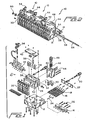
- FIGURE 1 is an exploded view of a new and improved fluid dispensing head assembly modular unit which has been constructed for use in accordance with the principles and teachings of the present invention, and which is generally indicated by the reference character 10, it is initially noted that the primary or major components of the new and improved fluid dispensing head assembly modular unit 10 which has been constructed for use in accordance with the principles and teachings of the present invention are substantially the same as, or virtually identical to, corresponding components of conventionally known fluid dispensing head assemblies, and consequently, such components will only be identified and briefly discussed but will not be discussed or described in detail in view of the fact that such components are well known and are not relevant to the specific characteristics or features of the present invention. Subsequently, the new features characteristic of the present invention comprising, for example, modifications to the existing or conventionally known components, will of course be disclosed and discussed in detail.
- the new and improved fluid dispensing head assembly modular unit 10 is, for example, particularly adapted for use in connection with the dispensing or deposition of hot melt adhesive, however, it is to be understood that the fluid dispensing head assembly modular unit 10 can be used, or can be adapted or modified, for the dispensing of fluids other than hot melt adhesives, such as, for example, cosmetic lotions, plastic materials, or the like. Accordingly, while such apparatus may be used to dispense or deposit any one of a plurality of different fluid materials, the following description will be oriented toward the dispensing or deposition of hot melt adhesive materials.
- a temperature sensor 24 is provided for controlling the energization of the cartridge heaters 18 so as to in turn control the temperature of the incoming air.
- Incoming air is supplied to the air distribution block 14 by means of an air hose connector 26 which is fluidically connected to a suitable air regulator, not shown.
- a service block 28 is adapted to be mounted atop the air heater block 12, and the service block 28 has operatively associated therewith, and mounted upon the front face thereof, a plurality of adhesive dispensing valves 30.
- the width dimension of the service block 28 is such as to accommodate, house, or mount six (6) adhesive dispensing valves 30 upon the front face thereof.
- the fabrication of the service block 28 wherein the service block 28 has the predetermined width dimension so as to be able to accommodate, house, or mount six (6) adhesive dispensing valves 30 upon the front face thereof is noted to be exemplary only in that the service block 28 can be provided with any other desirable predetermined width dimension such that, in turn, any desirable number of dispensing valves 30 can be mounted upon the front face thereof, such as, for example, eight (8), ten (10), or the like dispensing valves 30.
- An electrical connector 40 is also adapted to be operatively mounted upon the service block 28 so as to provide electrical power to the adhesive material heaters 36 as well as to the temperature sensor mechanism 38.
- a head or service block cover plate 42 is also mounted upon the upper surface of the service block 28 so as to close and seal the upper region of the service block 28.
- the air manifold 32 and the head or service block cover plate 42 both have predetermined width dimensions which match that of the service block 28, and that the service block 28 has a predetermined width dimension which matches that of the air heater block 12.
- the air manifold 32 and head or service block cover plate 42 are mounted upon the service block 28, and in turn, when the service block 28 is mounted upon the air heater block 12, all components have substantially the same width dimension whereby the overall width dimension of the particular fluid dispensing head assembly modular unit 10 is predetermined in accordance with the desired number of adhesive dispensing valves 30 which are to be mounted upon or incorporated within the fluid dispensing head assembly modular unit 10.
- a filter block 44 is mounted upon a rear or back surface portion of the service block 28, and the filter block 44 is provided with a basket-type filter component 46 as well as a threaded plug or nut 48 which is threadedly engaged within the filter block 44 so as to retain the filter component 46 therewithin.
- the filter component 46 serves to filter any debris or particles which may be contained within the incoming adhesive material which is conducted into the filter block 44 through means of a suitable port, not shown, provided within a rear surface portion of the filter block 44.
- a mounting plate or bracket 50 is also adapted to be fixedly secured to a side wall 52 of the service block 28.
- the mounting plate or bracket 50 also serves to thermally isolate the endmost one of the fluid dispensing head assembly modular units 10 from the adhesive dispensing or deposition machine, not shown.
- a plurality of the fluid dispensing head assembly modular units 10 is serially disposed in a side-by-side secured array so as to in effect readily and easily fabricate an extended array of fluid dispensing head assembly modular units 10 which comprises an increased number of adhesive material dispensing valves 30 so as to satisfy particular dispensing or deposition requirements attendant a particular dispensing or deposition operation or application.
- each one of the fluid dispensing head assembly modular units 10 is illustrated as comprising, for example, six hot melt material dispensing valves 30, in accordance with the principles and teachings of the present invention, each one of the fluid dispensing head assembly modular units 10 can alternatively comprise, for example, eight, ten, or the like, hot melt material dispensing valves 30.
- FIGURE 2 discloses three fluid dispensing head assembly modular units 10 which therefore comprise three sets of hot melt material dispensing valves 30 wherein each set of hot melt material dispensing valves 30 comprises six dispensing valves 30.
- the assemblage of fluid dispensing head assembly modular units 10 shown in FIGURE 2 comprises eighteen dispensing valves 30.
- the assemblage of fluid dispensing head assembly modular units can comprise two fluid dispensing head assembly modular units 10 wherein the total number of dispensing valves 30 disposed within the assemblage of fluid dispensing head assembly modular units 10 comprises twelve dispensing valves 30.
- a particular fluid dispensing head assembly modular unit 10 comprises eight dispensing valves 30, then when such modular unit 10 is combined or adjoined to a modular unit 10 comprising six dispensing valves 30, then the total number of dispensing valves comprising the assemblage of fluid dispensing head assembly modular units 10 comprises fourteen dispensing valves 30.
- each one of the service blocks 28 of each fluid dispensing head assembly modular unit 10 is provided with an axially extending throughbore 54.
- a threaded rod 56 having a predetermined axial length, is adapted to be disposed or inserted through the throughbores 54 of each service block 28 of each modular unit 10.
- a pair of dowel pins 58 are provided within, for example, each right side wall 52 of each service block 28 so as to be disposed within suitable apertures formed within, for example, each left side wall 52 of each service block 28.
- suitable washer and nut fastener components 60 may be threadedly secured upon the opposite ends of the threaded rod 56 whereby the plurality modular units 10 are now fixedly locked together.
Landscapes
- Engineering & Computer Science (AREA)
- General Engineering & Computer Science (AREA)
- Mechanical Engineering (AREA)
- Coating Apparatus (AREA)
- Feeding, Discharge, Calcimining, Fusing, And Gas-Generation Devices (AREA)
- Valve Housings (AREA)
- Nozzles (AREA)
- Branch Pipes, Bends, And The Like (AREA)
- Pipeline Systems (AREA)
Claims (7)
- Baugruppe aus modularen Schmelzklebstoff-Ausgabekopfanordnungs-Einheiten (10), jeweils zur Verbindung mit wenigstens einer anderen ähnlichen modularen Schmelzklebstoff-Ausgabekopfanordnungs-Einheit (10), wobei die Baugruppe Folgendes umfasst:eine erste und wenigstens eine zweite modulare Einheit (10),wobei die erste modulare Einheit Folgendes umfasst:gekennzeichnet durcheinen ersten Betriebsblock (28) zum Befördern von auszugebendem Schmelzklebstoffmaterial dadurch und der eine erste und eine gegenüberliegende zweite Seitenwand (52, 54) und einen hinteren oder Rückseitenabschnitt aufweist;eine erste vorgegebene Anzahl von Ausgabeventilen (30), die an dem ersten Betriebsblock (28) angebracht sind, um das durch den ersten Betriebsblock beförderte Material zu empfangen und auszugeben;
einen ersten Filterblock (44), der an dem hinteren oder Rückseitenabschnitt des ersten Betriebsblocks (28) angebracht ist, der einen Anschluss für das ankommende Schmelzklebstoffmaterial bereitstellt; und
wobei jede der wenigstens einen zweiten modularen Einheiten Folgendes umfasst:
einen zweiten Betriebsblock (28) zum Befördern von auszugebendem Schmelzklebstoffmaterial dadurch, wobei der zweite Betriebsblock (28) ähnlich dem ersten Betriebsblock (28) ist und eine dritte und eine gegenüberliegende vierte Seitenwand und einen hinteren oder Rückseitenabschnitt des zweiten Betriebsblocks aufweist;
eine zweite vorgegebene Anzahl von Ausgabeventilen (30), die an dem zweiten Betriebsblock (28) angebracht sind, um das durch den zweiten Betriebsblock beförderte Material zu empfangen und auszugeben;
einen zweiten Filterblock (44), der an dem hinteren oder Rückseitenabschnitt des zweiten Betriebsblocks angebracht ist, der einen Anschluss für das ankommende Schmelzklebstoffmaterial bereitstellt; und
Mittel (54, 56), die an dem ersten und an dem zweiten Betriebsblock angebracht sind, wobei der erste Betriebsblock (28) mit diesen Mitteln in einer nebeneinander befestigten Anordnung in der Weise mit dem zweiten Betriebsblock (28) der zweiten modularen Einheit (10) fest verbunden ist, dass die erste und die zweite modulare Einheit fest miteinander verbunden sind, wodurch die Baugruppe erzeugt ist. - Baugruppe nach Anspruch 1, wobei:die erste oder die zweite vorgegebene Anzahl von Ausgabeventilen sechs Ausgabeventile (30) umfasst.
- Baugruppe nach Anspruch 1, wobei:die erste oder die zweite vorgegebene Anzahl von Ausgabeventilen (30) aus einer Gruppe ausgewählt sind, die sechs, acht und zehn Ausgabeventile umfasst.
- Baugruppe nach Anspruch 1, wobei die an dem ersten und an dem zweiten Betriebsblock (28) angebrachten Mittel Folgendes umfassen:eine Gewindestange (56), die durch innerhalb der Betriebsblöcke (28) ausgebildete Durchgangsbohrungen (54) angeordnet ist, wodurch die modularen Einheiten miteinander verbinden sind.
- Baugruppe nach Anspruch 1, die ferner Folgendes umfasst:Passstifte (58), die an wenigstens einer Seitenwand (52) des ersten oder des zweiten Betriebsblocks (28) für die Einführung in in dem anderen des ersten und des zweiten Betriebsblocks (28) vorgesehene Öffnungen in der Weise vorgesehen sind, dass mehrere modulare Einheiten in Bezug aufeinander in einer Nebeneinanderanordnung ausgerichtet werden können.
- Baugruppe nach Anspruch 1, wobei:die Ausgabeventile Schmelzklebstoff-Ausgabeventile sind.
- Baugruppe nach Anspruch 1, wobei:die Baugruppe modularer Einheiten (10) mehr als zwei modulare Einheiten umfasst.
Applications Claiming Priority (2)
| Application Number | Priority Date | Filing Date | Title |
|---|---|---|---|
| US576556 | 2000-05-24 | ||
| US09/576,556 US6260583B1 (en) | 2000-05-24 | 2000-05-24 | Segmented stackable head design |
Publications (3)
| Publication Number | Publication Date |
|---|---|
| EP1157746A2 EP1157746A2 (de) | 2001-11-28 |
| EP1157746A3 EP1157746A3 (de) | 2003-05-28 |
| EP1157746B1 true EP1157746B1 (de) | 2012-08-08 |
Family
ID=24304917
Family Applications (1)
| Application Number | Title | Priority Date | Filing Date |
|---|---|---|---|
| EP20010109639 Expired - Lifetime EP1157746B1 (de) | 2000-05-24 | 2001-04-19 | Segmentierter, stapelbarer Düsenkopf |
Country Status (11)
| Country | Link |
|---|---|
| US (2) | US6260583B1 (de) |
| EP (1) | EP1157746B1 (de) |
| JP (2) | JP2001336657A (de) |
| KR (1) | KR100778464B1 (de) |
| CN (1) | CN1102714C (de) |
| AU (1) | AU746740B2 (de) |
| BR (1) | BR0101563A (de) |
| CA (1) | CA2344895C (de) |
| ES (1) | ES2391630T3 (de) |
| HK (1) | HK1043075A1 (de) |
| TW (1) | TW514597B (de) |
Families Citing this family (34)
| Publication number | Priority date | Publication date | Assignee | Title |
|---|---|---|---|---|
| US6220843B1 (en) | 1998-03-13 | 2001-04-24 | Nordson Corporation | Segmented die for applying hot melt adhesives or other polymer melts |
| US6906292B2 (en) * | 1998-10-29 | 2005-06-14 | Applera Corporation | Sample tray heater module |
| AUPQ528300A0 (en) * | 2000-01-27 | 2000-02-17 | Mebberson, Nicholas Barson | Fluid distribution device |
| US6499631B2 (en) * | 2001-01-26 | 2002-12-31 | Illinois Tool Works Inc. | Hot melt adhesive applicator |
| US6601741B2 (en) * | 2001-11-28 | 2003-08-05 | Illinois Tool Works Inc. | Laminated distribution manifold plate system |
| US7617951B2 (en) * | 2002-01-28 | 2009-11-17 | Nordson Corporation | Compact heated air manifolds for adhesive application |
| US6874708B2 (en) * | 2003-02-13 | 2005-04-05 | Illinois Tool Works Inc. | Automatic air-assisted manifold mounted gun |
| US7296706B2 (en) * | 2004-02-24 | 2007-11-20 | Nordson Corporation | Method and system for supporting and/or aligning components of a liquid dispensing system |
| USD536421S1 (en) | 2004-04-02 | 2007-02-06 | Nordson Corporation | Intake portion of a liquid dispensing valve |
| DE102004018597B3 (de) * | 2004-04-16 | 2005-12-01 | Dürr Systems GmbH | Applikationskopf zur Erzeugung einer Flüssigfolie |
| US7082262B2 (en) * | 2004-04-22 | 2006-07-25 | Nordson Corporation | Integral manifold for liquid material dispensing systems |
| US20050242108A1 (en) | 2004-04-30 | 2005-11-03 | Nordson Corporation | Liquid dispenser having individualized process air control |
| US20050284338A1 (en) * | 2004-06-01 | 2005-12-29 | Dwyer Patrick A | Hot melt adhesive |
| US7278550B2 (en) * | 2004-11-11 | 2007-10-09 | Nordson Corporation | Method and system for aligning components of a liquid dispensing system |
| US7631442B2 (en) | 2005-03-01 | 2009-12-15 | Louis Berkman Winter Products Company | Modular hydraulic power mechanism |
| KR100613780B1 (ko) * | 2005-03-09 | 2006-08-21 | 장동원 | 다노즐 액체정량밸브 |
| US7332692B2 (en) * | 2005-05-06 | 2008-02-19 | Illinois Tool Works Inc. | Redundant control circuit for hot melt adhesive assembly heater circuits and temperature sensors |
| US7351937B2 (en) * | 2005-05-06 | 2008-04-01 | Illinois Tool Works Inc. | Control circuits for hot melt adhesive heater circuits and applicator heads |
| ES2559003T3 (es) * | 2006-01-06 | 2016-02-10 | Nordson Corporation | Dispensador de líquidos con control individualizado de aire de proceso |
| EP2212600B1 (de) | 2008-03-28 | 2012-02-22 | FESTO AG & Co. KG | Ventilbatterie mit mehreren elektrisch betätigbaren fluidischen ventilen |
| KR101045003B1 (ko) | 2008-11-03 | 2011-06-29 | 장동원 | 다노즐 밸브어셈블리 |
| CN102261489A (zh) * | 2010-05-24 | 2011-11-30 | 浙江工正科技发展有限公司 | 耐溶剂带开闭功能的三通阀装置 |
| WO2013063294A1 (en) | 2011-10-27 | 2013-05-02 | Graco Minnesota Inc. | Melter cartridge |
| IN2014DN03195A (de) | 2011-10-27 | 2015-05-22 | Graco Minnesota Inc | |
| US9480996B2 (en) * | 2012-09-18 | 2016-11-01 | Ilinois Tool Works Inc. | Fluid dispensing system with nozzle heater |
| US8939330B2 (en) | 2013-03-13 | 2015-01-27 | Graco Minnesota Inc. | Removable module service seat |
| US9796492B2 (en) | 2015-03-12 | 2017-10-24 | Graco Minnesota Inc. | Manual check valve for priming a collapsible fluid liner for a sprayer |
| CN104819328B (zh) * | 2015-04-24 | 2017-06-13 | 南通华东油压科技有限公司 | 泵送阀铸造阀体 |
| DE112017002691T5 (de) * | 2016-05-27 | 2019-02-14 | Universal Instruments Corporation | Bestückungskopf mit einer Düsenheizvorrichtung, System und Verfahren zu ihrer Verwendung |
| KR101803748B1 (ko) * | 2017-04-07 | 2017-12-01 | 김보경 | 자동차 부품용 실러 토출 장치 |
| CN106976323A (zh) * | 2017-04-21 | 2017-07-25 | 汤振华 | 一种打印机模组安装调节机构 |
| ES3035649T3 (en) * | 2017-10-31 | 2025-09-05 | Nordson Corp | Liquid material dispensing system having a sleeve heater |
| JP7548936B2 (ja) * | 2019-04-05 | 2024-09-10 | ノードソン コーポレーション | アプリケータの空気マニホールド |
| TWI855085B (zh) | 2019-05-31 | 2024-09-11 | 美商葛萊兒明尼蘇達股份有限公司 | 手持式流體噴霧器 |
Citations (1)
| Publication number | Priority date | Publication date | Assignee | Title |
|---|---|---|---|---|
| WO1999046057A1 (en) * | 1998-03-13 | 1999-09-16 | Nordson Corporation | Segmented die for applying hot melt adhesives or other polymer melts |
Family Cites Families (29)
| Publication number | Priority date | Publication date | Assignee | Title |
|---|---|---|---|---|
| US3115282A (en) * | 1959-09-22 | 1963-12-24 | Walker Mfg Co | Forced feed dispensing system |
| JPS46614Y1 (de) * | 1966-09-14 | 1971-01-11 | ||
| JPS4911453Y1 (de) * | 1967-09-11 | 1974-03-19 | ||
| US3817269A (en) * | 1969-08-22 | 1974-06-18 | Int Basic Economy Corp | Integrated manifold circuits |
| US3886898A (en) * | 1973-12-19 | 1975-06-03 | Burroughs Corp | Multiple, contiguous stripe, extrusion coating apparatus |
| US4082324A (en) * | 1976-10-04 | 1978-04-04 | Obrecht Robert E | Connection arrangement for manifold blocks |
| US4079864A (en) * | 1976-12-15 | 1978-03-21 | Cox James R | Manifold for liquid dispensing apparatus |
| US4874014A (en) * | 1987-12-21 | 1989-10-17 | Fsi International, Inc. | Flow control manifold |
| JPH02261983A (ja) * | 1989-03-31 | 1990-10-24 | Ishikawajima Harima Heavy Ind Co Ltd | サイクル式分配弁 |
| JPH0741976Y2 (ja) * | 1989-08-01 | 1995-09-27 | エスエムシー株式会社 | 弁の取付装置 |
| JP3124287B2 (ja) * | 1990-11-27 | 2001-01-15 | エスエムシー株式会社 | マニホールド |
| JP2554686Y2 (ja) * | 1991-12-03 | 1997-11-17 | 太陽鉄工株式会社 | マニホルドブロック |
| DE4312730A1 (de) * | 1993-04-20 | 1994-10-27 | Festo Kg | Ventilstation |
| JP3275665B2 (ja) * | 1995-11-08 | 2002-04-15 | ダイキン工業株式会社 | 分配弁のスタック構造 |
| US5672269A (en) * | 1996-02-29 | 1997-09-30 | Illinois Tool Works Inc. | Filter/pressure relief assembly for an adhesive supply unit |
| US5605720A (en) * | 1996-04-04 | 1997-02-25 | J & M Laboratories Inc. | Method of continuously formulating and applying a hot melt adhesive |
| US5730174A (en) * | 1996-07-01 | 1998-03-24 | Lubriquip, Inc. | Solenoid valve cartridge for lubrication divider valves |
| US5806720A (en) | 1996-07-19 | 1998-09-15 | Illinois Tool Works Inc. | Multi position palletizer head for adhesive supply unit |
| US5802720A (en) * | 1996-10-04 | 1998-09-08 | Pribe; Christopher A. | Shaving cloth |
| JP3616475B2 (ja) * | 1997-05-23 | 2005-02-02 | 株式会社クボタ | バルブシステム |
| US6025729A (en) * | 1997-09-11 | 2000-02-15 | Delaware Capital Formation, Inc. | Floating spring probe wireless test fixture |
| JPH11294615A (ja) * | 1998-04-10 | 1999-10-29 | Ckd Corp | 集積弁 |
| US5934562A (en) * | 1998-04-15 | 1999-08-10 | Illinois Tool Works Inc. | Hot melt adhesive dispensing system with laminated air heater |
| US6422428B1 (en) * | 1998-04-20 | 2002-07-23 | Nordson Corporation | Segmented applicator for hot melt adhesives or other thermoplastic materials |
| JPH11325291A (ja) * | 1998-05-14 | 1999-11-26 | Smc Corp | 切換弁用マニホールド |
| CZ296370B6 (cs) * | 1998-06-22 | 2006-02-15 | Akzo Nobel N. V. | Zarízení a zpusob nanásení lepidla |
| JP2000070818A (ja) * | 1998-09-03 | 2000-03-07 | San Tool:Kk | ホットメルト接着剤スプレー塗布装置における加熱装置 |
| US6089413A (en) * | 1998-09-15 | 2000-07-18 | Nordson Corporation | Liquid dispensing and recirculating module |
| US6814310B2 (en) * | 2002-11-26 | 2004-11-09 | Nordson Corporation | Metered liquid dispensing system |
-
2000
- 2000-05-24 US US09/576,556 patent/US6260583B1/en not_active Expired - Lifetime
-
2001
- 2001-01-29 US US09/770,182 patent/US6286551B1/en not_active Expired - Lifetime
- 2001-03-14 JP JP2001072775A patent/JP2001336657A/ja active Pending
- 2001-03-28 KR KR1020010016222A patent/KR100778464B1/ko not_active Expired - Lifetime
- 2001-04-19 ES ES01109639T patent/ES2391630T3/es not_active Expired - Lifetime
- 2001-04-19 EP EP20010109639 patent/EP1157746B1/de not_active Expired - Lifetime
- 2001-04-23 CA CA 2344895 patent/CA2344895C/en not_active Expired - Fee Related
- 2001-04-24 BR BR0101563A patent/BR0101563A/pt active IP Right Grant
- 2001-04-27 CN CN01115538A patent/CN1102714C/zh not_active Expired - Lifetime
- 2001-05-17 AU AU46018/01A patent/AU746740B2/en not_active Ceased
- 2001-06-15 TW TW90110702A patent/TW514597B/zh not_active IP Right Cessation
-
2002
- 2002-05-21 HK HK02103800.2A patent/HK1043075A1/en unknown
-
2012
- 2012-03-13 JP JP2012055999A patent/JP5363602B2/ja not_active Expired - Lifetime
Patent Citations (1)
| Publication number | Priority date | Publication date | Assignee | Title |
|---|---|---|---|---|
| WO1999046057A1 (en) * | 1998-03-13 | 1999-09-16 | Nordson Corporation | Segmented die for applying hot melt adhesives or other polymer melts |
Also Published As
| Publication number | Publication date |
|---|---|
| CA2344895C (en) | 2003-11-25 |
| KR20010107541A (ko) | 2001-12-07 |
| ES2391630T3 (es) | 2012-11-28 |
| JP5363602B2 (ja) | 2013-12-11 |
| AU4601801A (en) | 2001-12-13 |
| JP2012137186A (ja) | 2012-07-19 |
| CA2344895A1 (en) | 2001-11-24 |
| US6286551B1 (en) | 2001-09-11 |
| EP1157746A2 (de) | 2001-11-28 |
| CN1324995A (zh) | 2001-12-05 |
| CN1102714C (zh) | 2003-03-05 |
| EP1157746A3 (de) | 2003-05-28 |
| BR0101563A (pt) | 2002-01-02 |
| US6260583B1 (en) | 2001-07-17 |
| JP2001336657A (ja) | 2001-12-07 |
| HK1043075A1 (en) | 2002-09-06 |
| AU746740B2 (en) | 2002-05-02 |
| KR100778464B1 (ko) | 2007-11-21 |
| TW514597B (en) | 2002-12-21 |
Similar Documents
| Publication | Publication Date | Title |
|---|---|---|
| US6260583B1 (en) | Segmented stackable head design | |
| US10155241B2 (en) | Liquid dispenser having individualized process air control | |
| US6601741B2 (en) | Laminated distribution manifold plate system | |
| US6422428B1 (en) | Segmented applicator for hot melt adhesives or other thermoplastic materials | |
| US6814310B2 (en) | Metered liquid dispensing system | |
| EP1588771B1 (de) | Integrales Verteilerrohr für eine Flüssigkeitsabgabesystem | |
| EP1166890A2 (de) | Klebstoffdüse mit einem geteilten Auslass | |
| EP1331040A3 (de) | Kompakter Verteiler für Heissluft zum Auftragen von Klebstoff | |
| US7723647B2 (en) | Information communication systems between components of a hot melt adhesive material dispensing system | |
| AU713576B2 (en) | Hot melt adhesive dispensing system with laminated air heater | |
| US5370319A (en) | Slot nozzle for edge banding | |
| MXPA01005143A (en) | Segmented stackable head design |
Legal Events
| Date | Code | Title | Description |
|---|---|---|---|
| PUAI | Public reference made under article 153(3) epc to a published international application that has entered the european phase |
Free format text: ORIGINAL CODE: 0009012 |
|
| AK | Designated contracting states |
Kind code of ref document: A2 Designated state(s): AT BE CH CY DE DK ES FI FR GB GR IE IT LI LU MC NL PT SE TR |
|
| AX | Request for extension of the european patent |
Free format text: AL;LT;LV;MK;RO;SI |
|
| PUAL | Search report despatched |
Free format text: ORIGINAL CODE: 0009013 |
|
| AK | Designated contracting states |
Designated state(s): AT BE CH CY DE DK ES FI FR GB GR IE IT LI LU MC NL PT SE TR |
|
| AX | Request for extension of the european patent |
Extension state: AL LT LV MK RO SI |
|
| 17P | Request for examination filed |
Effective date: 20031110 |
|
| AKX | Designation fees paid |
Designated state(s): AT BE CH CY DE DK ES FI FR GB GR IE IT LI LU MC NL PT SE TR |
|
| 17Q | First examination report despatched |
Effective date: 20061130 |
|
| REG | Reference to a national code |
Ref country code: DE Ref legal event code: R079 Ref document number: 60146937 Country of ref document: DE Free format text: PREVIOUS MAIN CLASS: B05C0005020000 Ipc: F16K0027000000 |
|
| GRAP | Despatch of communication of intention to grant a patent |
Free format text: ORIGINAL CODE: EPIDOSNIGR1 |
|
| RIC1 | Information provided on ipc code assigned before grant |
Ipc: B05C 5/02 20060101ALI20120130BHEP Ipc: F16K 27/00 20060101AFI20120130BHEP |
|
| GRAS | Grant fee paid |
Free format text: ORIGINAL CODE: EPIDOSNIGR3 |
|
| GRAA | (expected) grant |
Free format text: ORIGINAL CODE: 0009210 |
|
| AK | Designated contracting states |
Kind code of ref document: B1 Designated state(s): AT BE CH CY DE DK ES FI FR GB GR IE IT LI LU MC NL PT SE TR |
|
| REG | Reference to a national code |
Ref country code: GB Ref legal event code: FG4D |
|
| REG | Reference to a national code |
Ref country code: CH Ref legal event code: EP Ref country code: AT Ref legal event code: REF Ref document number: 569960 Country of ref document: AT Kind code of ref document: T Effective date: 20120815 |
|
| REG | Reference to a national code |
Ref country code: IE Ref legal event code: FG4D |
|
| REG | Reference to a national code |
Ref country code: DE Ref legal event code: R096 Ref document number: 60146937 Country of ref document: DE Effective date: 20121011 |
|
| REG | Reference to a national code |
Ref country code: SE Ref legal event code: TRGR |
|
| REG | Reference to a national code |
Ref country code: ES Ref legal event code: FG2A Ref document number: 2391630 Country of ref document: ES Kind code of ref document: T3 Effective date: 20121128 |
|
| REG | Reference to a national code |
Ref country code: NL Ref legal event code: VDEP Effective date: 20120808 |
|
| REG | Reference to a national code |
Ref country code: AT Ref legal event code: MK05 Ref document number: 569960 Country of ref document: AT Kind code of ref document: T Effective date: 20120808 |
|
| PG25 | Lapsed in a contracting state [announced via postgrant information from national office to epo] |
Ref country code: AT Free format text: LAPSE BECAUSE OF FAILURE TO SUBMIT A TRANSLATION OF THE DESCRIPTION OR TO PAY THE FEE WITHIN THE PRESCRIBED TIME-LIMIT Effective date: 20120808 Ref country code: CY Free format text: LAPSE BECAUSE OF FAILURE TO SUBMIT A TRANSLATION OF THE DESCRIPTION OR TO PAY THE FEE WITHIN THE PRESCRIBED TIME-LIMIT Effective date: 20120808 Ref country code: FI Free format text: LAPSE BECAUSE OF FAILURE TO SUBMIT A TRANSLATION OF THE DESCRIPTION OR TO PAY THE FEE WITHIN THE PRESCRIBED TIME-LIMIT Effective date: 20120808 |
|
| PG25 | Lapsed in a contracting state [announced via postgrant information from national office to epo] |
Ref country code: BE Free format text: LAPSE BECAUSE OF FAILURE TO SUBMIT A TRANSLATION OF THE DESCRIPTION OR TO PAY THE FEE WITHIN THE PRESCRIBED TIME-LIMIT Effective date: 20120808 Ref country code: PT Free format text: LAPSE BECAUSE OF FAILURE TO SUBMIT A TRANSLATION OF THE DESCRIPTION OR TO PAY THE FEE WITHIN THE PRESCRIBED TIME-LIMIT Effective date: 20121210 Ref country code: GR Free format text: LAPSE BECAUSE OF FAILURE TO SUBMIT A TRANSLATION OF THE DESCRIPTION OR TO PAY THE FEE WITHIN THE PRESCRIBED TIME-LIMIT Effective date: 20121109 |
|
| PG25 | Lapsed in a contracting state [announced via postgrant information from national office to epo] |
Ref country code: NL Free format text: LAPSE BECAUSE OF FAILURE TO SUBMIT A TRANSLATION OF THE DESCRIPTION OR TO PAY THE FEE WITHIN THE PRESCRIBED TIME-LIMIT Effective date: 20120808 |
|
| PG25 | Lapsed in a contracting state [announced via postgrant information from national office to epo] |
Ref country code: DK Free format text: LAPSE BECAUSE OF FAILURE TO SUBMIT A TRANSLATION OF THE DESCRIPTION OR TO PAY THE FEE WITHIN THE PRESCRIBED TIME-LIMIT Effective date: 20120808 |
|
| PLBE | No opposition filed within time limit |
Free format text: ORIGINAL CODE: 0009261 |
|
| STAA | Information on the status of an ep patent application or granted ep patent |
Free format text: STATUS: NO OPPOSITION FILED WITHIN TIME LIMIT |
|
| 26N | No opposition filed |
Effective date: 20130510 |
|
| REG | Reference to a national code |
Ref country code: DE Ref legal event code: R097 Ref document number: 60146937 Country of ref document: DE Effective date: 20130510 |
|
| PG25 | Lapsed in a contracting state [announced via postgrant information from national office to epo] |
Ref country code: MC Free format text: LAPSE BECAUSE OF FAILURE TO SUBMIT A TRANSLATION OF THE DESCRIPTION OR TO PAY THE FEE WITHIN THE PRESCRIBED TIME-LIMIT Effective date: 20120808 |
|
| REG | Reference to a national code |
Ref country code: CH Ref legal event code: PL |
|
| REG | Reference to a national code |
Ref country code: IE Ref legal event code: MM4A |
|
| PG25 | Lapsed in a contracting state [announced via postgrant information from national office to epo] |
Ref country code: CH Free format text: LAPSE BECAUSE OF NON-PAYMENT OF DUE FEES Effective date: 20130430 Ref country code: LI Free format text: LAPSE BECAUSE OF NON-PAYMENT OF DUE FEES Effective date: 20130430 |
|
| PG25 | Lapsed in a contracting state [announced via postgrant information from national office to epo] |
Ref country code: IE Free format text: LAPSE BECAUSE OF NON-PAYMENT OF DUE FEES Effective date: 20130419 |
|
| PG25 | Lapsed in a contracting state [announced via postgrant information from national office to epo] |
Ref country code: LU Free format text: LAPSE BECAUSE OF NON-PAYMENT OF DUE FEES Effective date: 20130419 |
|
| REG | Reference to a national code |
Ref country code: FR Ref legal event code: PLFP Year of fee payment: 16 |
|
| REG | Reference to a national code |
Ref country code: FR Ref legal event code: PLFP Year of fee payment: 17 |
|
| REG | Reference to a national code |
Ref country code: FR Ref legal event code: PLFP Year of fee payment: 18 |
|
| PGFP | Annual fee paid to national office [announced via postgrant information from national office to epo] |
Ref country code: ES Payment date: 20190701 Year of fee payment: 14 |
|
| PGFP | Annual fee paid to national office [announced via postgrant information from national office to epo] |
Ref country code: SE Payment date: 20190429 Year of fee payment: 19 |
|
| PGFP | Annual fee paid to national office [announced via postgrant information from national office to epo] |
Ref country code: TR Payment date: 20200331 Year of fee payment: 20 |
|
| PGFP | Annual fee paid to national office [announced via postgrant information from national office to epo] |
Ref country code: DE Payment date: 20200429 Year of fee payment: 20 Ref country code: FR Payment date: 20200427 Year of fee payment: 20 |
|
| PGFP | Annual fee paid to national office [announced via postgrant information from national office to epo] |
Ref country code: IT Payment date: 20200423 Year of fee payment: 20 Ref country code: GB Payment date: 20200427 Year of fee payment: 20 |
|
| PG25 | Lapsed in a contracting state [announced via postgrant information from national office to epo] |
Ref country code: SE Free format text: LAPSE BECAUSE OF NON-PAYMENT OF DUE FEES Effective date: 20200420 |
|
| REG | Reference to a national code |
Ref country code: DE Ref legal event code: R071 Ref document number: 60146937 Country of ref document: DE |
|
| REG | Reference to a national code |
Ref country code: GB Ref legal event code: PE20 Expiry date: 20210418 |
|
| PG25 | Lapsed in a contracting state [announced via postgrant information from national office to epo] |
Ref country code: GB Free format text: LAPSE BECAUSE OF EXPIRATION OF PROTECTION Effective date: 20210418 |
|
| REG | Reference to a national code |
Ref country code: ES Ref legal event code: FD2A Effective date: 20210903 |
|
| REG | Reference to a national code |
Ref country code: HK Ref legal event code: WD Ref document number: 1043075 Country of ref document: HK |
|
| PG25 | Lapsed in a contracting state [announced via postgrant information from national office to epo] |
Ref country code: ES Free format text: LAPSE BECAUSE OF NON-PAYMENT OF DUE FEES Effective date: 20200420 |