EP1157763B1 - Verfahren und Vorrichtung zum Herstellen von Akkumulatorplatten - Google Patents
Verfahren und Vorrichtung zum Herstellen von Akkumulatorplatten Download PDFInfo
- Publication number
- EP1157763B1 EP1157763B1 EP01112358A EP01112358A EP1157763B1 EP 1157763 B1 EP1157763 B1 EP 1157763B1 EP 01112358 A EP01112358 A EP 01112358A EP 01112358 A EP01112358 A EP 01112358A EP 1157763 B1 EP1157763 B1 EP 1157763B1
- Authority
- EP
- European Patent Office
- Prior art keywords
- strip
- expansion
- tool
- lugs
- meshes
- Prior art date
- Legal status (The legal status is an assumption and is not a legal conclusion. Google has not performed a legal analysis and makes no representation as to the accuracy of the status listed.)
- Expired - Lifetime
Links
Images



Classifications
-
- B—PERFORMING OPERATIONS; TRANSPORTING
- B21—MECHANICAL METAL-WORKING WITHOUT ESSENTIALLY REMOVING MATERIAL; PUNCHING METAL
- B21D—WORKING OR PROCESSING OF SHEET METAL OR METAL TUBES, RODS OR PROFILES WITHOUT ESSENTIALLY REMOVING MATERIAL; PUNCHING METAL
- B21D31/00—Other methods for working sheet metal, metal tubes, metal profiles
- B21D31/04—Expanding other than provided for in groups B21D1/00 - B21D28/00, e.g. for making expanded metal
- B21D31/043—Making use of slitting discs or punch cutters
-
- Y—GENERAL TAGGING OF NEW TECHNOLOGICAL DEVELOPMENTS; GENERAL TAGGING OF CROSS-SECTIONAL TECHNOLOGIES SPANNING OVER SEVERAL SECTIONS OF THE IPC; TECHNICAL SUBJECTS COVERED BY FORMER USPC CROSS-REFERENCE ART COLLECTIONS [XRACs] AND DIGESTS
- Y02—TECHNOLOGIES OR APPLICATIONS FOR MITIGATION OR ADAPTATION AGAINST CLIMATE CHANGE
- Y02E—REDUCTION OF GREENHOUSE GAS [GHG] EMISSIONS, RELATED TO ENERGY GENERATION, TRANSMISSION OR DISTRIBUTION
- Y02E60/00—Enabling technologies; Technologies with a potential or indirect contribution to GHG emissions mitigation
- Y02E60/10—Energy storage using batteries
-
- Y—GENERAL TAGGING OF NEW TECHNOLOGICAL DEVELOPMENTS; GENERAL TAGGING OF CROSS-SECTIONAL TECHNOLOGIES SPANNING OVER SEVERAL SECTIONS OF THE IPC; TECHNICAL SUBJECTS COVERED BY FORMER USPC CROSS-REFERENCE ART COLLECTIONS [XRACs] AND DIGESTS
- Y10—TECHNICAL SUBJECTS COVERED BY FORMER USPC
- Y10T—TECHNICAL SUBJECTS COVERED BY FORMER US CLASSIFICATION
- Y10T29/00—Metal working
- Y10T29/10—Battery-grid making
-
- Y—GENERAL TAGGING OF NEW TECHNOLOGICAL DEVELOPMENTS; GENERAL TAGGING OF CROSS-SECTIONAL TECHNOLOGIES SPANNING OVER SEVERAL SECTIONS OF THE IPC; TECHNICAL SUBJECTS COVERED BY FORMER USPC CROSS-REFERENCE ART COLLECTIONS [XRACs] AND DIGESTS
- Y10—TECHNICAL SUBJECTS COVERED BY FORMER USPC
- Y10T—TECHNICAL SUBJECTS COVERED BY FORMER US CLASSIFICATION
- Y10T29/00—Metal working
- Y10T29/18—Expanded metal making
-
- Y—GENERAL TAGGING OF NEW TECHNOLOGICAL DEVELOPMENTS; GENERAL TAGGING OF CROSS-SECTIONAL TECHNOLOGIES SPANNING OVER SEVERAL SECTIONS OF THE IPC; TECHNICAL SUBJECTS COVERED BY FORMER USPC CROSS-REFERENCE ART COLLECTIONS [XRACs] AND DIGESTS
- Y10—TECHNICAL SUBJECTS COVERED BY FORMER USPC
- Y10T—TECHNICAL SUBJECTS COVERED BY FORMER US CLASSIFICATION
- Y10T29/00—Metal working
- Y10T29/18—Expanded metal making
- Y10T29/185—Expanded metal making by use of reciprocating perforator
-
- Y—GENERAL TAGGING OF NEW TECHNOLOGICAL DEVELOPMENTS; GENERAL TAGGING OF CROSS-SECTIONAL TECHNOLOGIES SPANNING OVER SEVERAL SECTIONS OF THE IPC; TECHNICAL SUBJECTS COVERED BY FORMER USPC CROSS-REFERENCE ART COLLECTIONS [XRACs] AND DIGESTS
- Y10—TECHNICAL SUBJECTS COVERED BY FORMER USPC
- Y10T—TECHNICAL SUBJECTS COVERED BY FORMER US CLASSIFICATION
- Y10T29/00—Metal working
- Y10T29/49—Method of mechanical manufacture
- Y10T29/49394—Accumulator making
-
- Y—GENERAL TAGGING OF NEW TECHNOLOGICAL DEVELOPMENTS; GENERAL TAGGING OF CROSS-SECTIONAL TECHNOLOGIES SPANNING OVER SEVERAL SECTIONS OF THE IPC; TECHNICAL SUBJECTS COVERED BY FORMER USPC CROSS-REFERENCE ART COLLECTIONS [XRACs] AND DIGESTS
- Y10—TECHNICAL SUBJECTS COVERED BY FORMER USPC
- Y10T—TECHNICAL SUBJECTS COVERED BY FORMER US CLASSIFICATION
- Y10T29/00—Metal working
- Y10T29/49—Method of mechanical manufacture
- Y10T29/496—Multiperforated metal article making
Definitions
- the present invention relates to a method of producing accumulator plates according to the preamble of claim 1 and an expansion machine for the production of accumulator plates according to the preamble of claim 4.
- a method and a machine of this type are known, for example, from US-A-4 220 030.
- connection appendages or lugs of the individual plates a plurality of openings or windows, separated by transverse bridges which are to form the connection appendages or lugs, is formed in the non-expanded, central portion of the grid strip, downstream of the expansion machine, in a scrap removal and sizing machine.
- Expansion machines for producing grid strips in which the strip is supplied by means of a pulling device disposed downstream of the expansion punching tool and pulling the strip along with continuous motion have been proposed.
- the expansion punching tool is subjected to two combined movements, that is: a vertical oscillatory movement for the cutting of the strip and a horizontal oscillatory movement parallel to the direction of movement of the strip so that the meshes are cut with zero relative velocity between the tool and the strip.
- a rotary cutter is also installed downstream of the expansion tool and punches the windows in the central portion or band of the grid strip.
- the strip can be fed through the expansion machine by means of an indexed pulling wheel having a plurality of peripheral projections which engage in the holes pre-formed in the strip, bringing about a stepped movement thereof.
- a device similar to the indexed wheel is used for feeding the strip so that the windows are always formed in the desired positions relative to the meshes of the grid portion of the plates. This method is in fact quite complex and does not generally permit good productivity.
- An object of the present invention is therefore to propose a method and a machine which prevent the disadvantages of the solutions outlined above.
- Figure 1 shows schematically and partially, a plant for the production of accumulator grid plates.
- the plant comprises a reel 1 supported for rotation about a horizontal axis by a support 2.
- a continuous strip of rolled metal, for example lead alloy, is wound on the reel.
- the strip 3 Downstream of the reel 1, the strip 3 reaches an expansion machine, generally indicated 4.
- This machine comprises a base 5 which supports, on the input side, a thrust device 6 for causing the strip 3 to advance in steps.
- the device 6 is, for example, a so-called intermittent feeder, driven by an electric motor or by a mechanical device.
- the machine 4 Downstream of the feeder 6 the machine 4 has an expansion section, generally indicated 7 in Figure 1, downstream of which in turn there is a pulling device 8 of known type which, in operation, can keep the strip 3 permanently subjected to a slight tension in the direction of advance of the strip, indicated by the arrows F.
- the expansion section 7 of the machine 4 comprises a base plate 9 which is fixed to the base 5 and to which a matrix or complementary expansion tool 11 of known type in turn is fixed.
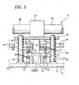
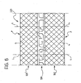
- the matrix 11 comprises a generally elongate support 10 tapered in the direction of advance of the strip 3 and carrying, on top of its side portions, two sets of fixed blades 12 and 12' for cooperating with corresponding punches 13 and 13' of an expansion tool, generally indicated 14 (see also Figures 4 and 5).
- the punches 13, 13' of the expansion tool 14 are fixed to the two sides of an elongate support bar 15 tapered in steps in the direction of advance F of the strip ( Figure 5).
- the expansion tool 14 is fixed to the lower face of a substantially horizontal plate 16 which is movable vertically in known manner, for example, by means of one or more motor-driven horizontal shafts arranged transverse the direction of advance of the strip and having respective cams or eccentric elements cooperating with the plate.
- Vertical compression springs are associated with the plate 16 in a known manner, not shown in Figure 3, and tend to keep the plate in the raised position shown in that drawing.
- the expansion section as described up to now is of a known type, for example, of the type described in detail in the US patent cited above.
- the expansion tool 14 is intended to be lowered and raised cyclically in operation, in synchronism with the intermittent advance of the strip 3 so as to bring about a progressive expansion of the longitudinal and lateral portions of the strip 3 by successive incisions and plastic deformations thereof.
- a grid strip, indicated 103 in Figure 2 is thus formed, in known manner, and has a non-expanded central portion or band 104 between two longitudinal grid portions 105 and 105'.
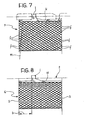
- the grid strip 103 is intended to permit the production of accumulator plates P each having, as can be seen, for example, in Figures 7 and 8, a grid portion G with a head portion H which is not formed as a grid and which forms a connection appendage or lug I.
- the production of the plates P from the grid strip 103 involves the shearing of the strip along transverse lines such as those indicated L in that drawing, as well as the formation of a plurality of openings or windows O, O' (identical or different) in the central portion or band 104 of the strip and the blanking of the appendages or lugs along the lines indicated 1 in Figure 6.
- the openings or windows O, O' are advantageously formed in the expansion section 7 of the machine 4, as will be described further below.
- the shearing and separation of the plates P along the lines L and 1 of Figure 6, however, are performed in a cutting station of known type, indicated 18 in Figure 1, disposed downstream of a station 17 for pasting of the grid strip 103.
- Openings 23 are correspondingly formed in the base support 10 of the complementary tool or matrix 11 ( Figure 3) for receiving the punches 20, 20' when the plate 19 is lowered in order to punch a series of openings O, O'.
- the plate 19 is supported for sliding vertically relative to guide pillars 24 fixed to the base plate 9, around which helical compression springs 25, which tend to keep the plate 19 in a raised position, are arranged.
- the lowering of the plate 19 and of the associated punches 20, 20' can be controlled by means of a horizontal motor-driven shaft 26 having at least one drive eccentric or cam 27 which cooperates with the plate.
- the expansion section 7 of the expansion machine 4 as described above thus enables openings or windows O, O' to be produced in phase with the operation of the expansion punching tool 14. This makes it possible to ensure that the connection appendages or lugs I of the plates P are always positioned in the desired manner relative to the transverse rows or lines of nodes of the meshes of the plates.
- connection appendage or lug I should be positioned, relative to the end edges S of a plate P, substantially in the manner shown in Figure 8, that is, at a predetermined distance D from one of the two borders or edges S of the plate. Moreover, these edges S ideally extend in the region of transverse lines of nodes of the meshes of the grid portion G of the plate, as can be seen in Figure 8.
- the lines along which the nodes of the meshes of the grid portion of a plate are aligned transversely may not be exactly perpendicular to the axis of the head H but may be slightly inclined, as indicated by the line of nodes indicated m in Figure 7.
- This fault in the alignment of the nodes leads to the disadvantage that, at the edges S, the grid portion G of the plate of Figure 7 has free limbs or ends f which may subsequently cause undesired contact between plates with different polarities in an accumulator.
- the expansion punching tool 14 of the machine 4 is advantageously formed with punches 13 of the type shown in Figures 9 and 10.
- the first tooth 40a of each punch 13 (13') is a mesh-reshaping tooth and is followed by n-1 cutting teeth 40b.
- the feed device 6 and the associated pulling device 8 which are associated with the expansion machine 4 are arranged to feed the strip 3 in jumps or steps of a magnitude substantially corresponding to the overall longitudinal extent of the n-1 cutting teeth 40b, each time.
- the arrangement as a whole is such that, after the strip has advanced by one step, the reshaping tooth 40a of each punch 13 (13') engages in the mesh previously cut in the strip 3 by the last of the cutting teeth 40b, that is, by the tooth situated farthest to the left as seen in Figures 9 and 10.
- the invention is not limited to the embodiment described in which the punches 20 (20') are operable separately from the expansion punching tool 14.
Landscapes
- Engineering & Computer Science (AREA)
- Mechanical Engineering (AREA)
- Cell Electrode Carriers And Collectors (AREA)
- Punching Or Piercing (AREA)
- Supply Devices, Intensifiers, Converters, And Telemotors (AREA)
Claims (4)
- Verfahren für die Herstellung von Akkumulatorenplatten (P), die entsprechende Verbindungsansätze oder Verbindungslaschen (I) besitzen, aus einem unbearbeiteten Streifen (3),
wobei das Verfahren folgende Schritte enthält:dadurch gekennzeichnet, dass die Öffnungen oder Fenster (O, O') in der Expansionsmaschine (4) von Stempeln (20, 20') ausgebildet werden, die synchron mit dem Betrieb des Expansions-Stanzwerkzeugs (14) betrieben werden, wodurch die Verbindungsansätze oder Verbindungslaschen (I) in der Expansionsmaschine (4) an vorgegebenen Stellen relativ zu den Querreihen der Knotenpunkte der Maschen der in Längsrichtung verlaufenden Gitterteile (105, 105') ausgebildet werden.Bewegen eines Streifens (3) durch eine Expansionsmaschine (4), die zumindest ein Expansions-Stanzwerkzeug (14) sowie ein zugeordnetes komplementäres Werkzeug oder Matrize (11) besitzt,Veranlassen, dass die Expansionsmaschine (4, 7) synchron mit der Bewegung des Streifens (3) betrieben wird, um einen Gitterstreifen (103) auszubilden, der ein nicht expandiertes Mittelband oder Mittelteil (104) sowie neben dem Mittelband oder Mittelteil (104) zwei in Längsrichtung verlaufende Gitterteile (105, 105') besitzt, die Maschen mit Querreihen von Knotenpunkten bilden, undAusbilden im nicht expandierten Mittelband (104) von einer Vielzahl von Öffnungen oder Fenstern (O, O'), die durch querliegende Brücken getrennt sind, die dazu dienen, um die Verbindungsansätze oder Verbindungslaschen (I) der Platten (P) zu bilden; - Verfahren gemäß Anspruch 1, wobei der unbearbeitete Streifen (3) zur Expansionsmaschine (4) schrittweise von einer im Schritt geschalteten Vorschubeinrichtung (6), die stromaufwärts des Expansionswerkzeugs (14) angeordnet ist, sowie einer zugeordneten, auf Zug arbeitenden Einrichtung (8) vorgeschoben wird, die stromabwärts des Expansionswerkzeugs (14) angeordnet ist.
- Verfahren gemäß Anspruch 1 oder Anspruch 2, wobei das Expansions-Stanzwerkzeug (14) eine Vielzahl von Stempeln (13, 13') enthält, von denen jeder n (n ≥ 2) Zähne (40a, 40b) besitzt, von denen der erste Zahn (40a) ein Zahn zum Neuformen der Maschen ist und die anderen n-1 Zähne Schneidezähne (40b) sind, wobei die Schneidezähne (40b) in den Streifen immer dann n-1 Maschen schneiden können, wenn das Expansions-Stanzwerkzeug (14) in den Streifen (3) eingreift, wobei der Streifen (3) bei jedem Schritt um einen Abstand vorgeschoben wird, der im Wesentlichen der gesamten Ausdehnung in Längsrichtung der Schneidezähne (40b) eines Stempels (13, 13') entspricht, so dass bei jedem Schritt des Streifens (3, 103) der Zahn für die Neuformung der Maschen (40a) in jene Masche eingreift, die vorher mit dem letzten der Schneidezähne (40b) des selben Stempels (13, 13') geschnitten wurde.
- Expansionsmaschine (4) für die Herstellung von Akkumulatorenplatten (P), die entsprechende Verbindungsansätze oder Verbindungslaschen (I) besitzen, aus einem unbearbeiteten Streifen (3), wobei die Maschine enthält:wobei die Expansionsmaschine (4) dadurch gekennzeichnet ist, dass sie eine Stanzeinrichtung (20, 20') enthält, die synchron mit dem Expansionswerkzeug (14) betrieben werden kann, um im Mittelband (104) eine Vielzahl von Öffnungen oder Fenstern (O, O') auszubilden, die durch Brücken getrennt sind, die dazu vorgesehen sind, um die Verbindungsansätze oder Verbindungslaschen (I) der Platten (P) zu bilden, wodurch die Verbindungsansätze oder Verbindungslaschen (I) an vorgegebenen Stellen relativ zu den Querreihen der Knotenpunkte der Maschen der in Längsrichtung verlaufenden Gitterteile (105, 105') ausgebildet werden.zumindest ein Expansions-Stanzwerkzeug (14), das relativ zu einem zugeordneten komplementären Werkzeug oder Matrize (11) bewegbar ist und synchron mit dem Vorschub eines zugeführten, unbearbeiteten Streifens (3) betrieben wird, um im Betrieb einen Gitterstreifen (103) mit einem nicht expandierten Mittelteil oder Mittelband (104) sowie neben dem Mittelband (104) zwei seitliche Gitterteile (105, 105') auszubilden, die Maschen mit Querreihen von Knotenpunkten bilden,
Applications Claiming Priority (2)
| Application Number | Priority Date | Filing Date | Title |
|---|---|---|---|
| IT2000TO000467A IT1320358B1 (it) | 2000-05-23 | 2000-05-23 | Procedimento e macchina per la realizzazione di piastre peraccumulatori. |
| ITTO000467 | 2000-05-23 |
Publications (2)
| Publication Number | Publication Date |
|---|---|
| EP1157763A1 EP1157763A1 (de) | 2001-11-28 |
| EP1157763B1 true EP1157763B1 (de) | 2005-10-05 |
Family
ID=11457742
Family Applications (1)
| Application Number | Title | Priority Date | Filing Date |
|---|---|---|---|
| EP01112358A Expired - Lifetime EP1157763B1 (de) | 2000-05-23 | 2001-05-21 | Verfahren und Vorrichtung zum Herstellen von Akkumulatorplatten |
Country Status (5)
| Country | Link |
|---|---|
| US (1) | US6425181B2 (de) |
| EP (1) | EP1157763B1 (de) |
| DE (1) | DE60113764T2 (de) |
| ES (1) | ES2249351T3 (de) |
| IT (1) | IT1320358B1 (de) |
Families Citing this family (4)
| Publication number | Priority date | Publication date | Assignee | Title |
|---|---|---|---|---|
| FR2792231B1 (fr) * | 1999-04-16 | 2001-06-15 | Andreas Kogler | Materiau de garnissage |
| CN104206976A (zh) * | 2014-08-05 | 2014-12-17 | 杨慧 | 改善微循环型补钙猪皮味玉米糁及其制备方法 |
| CN116830321A (zh) * | 2021-02-12 | 2023-09-29 | 松下知识产权经营株式会社 | 非水电解质电池 |
| CN114558936B (zh) * | 2022-03-03 | 2023-08-04 | 浙江省浦江宏达有限公司 | 净水设备金属滤网生产用冲压设备及使用方法 |
Family Cites Families (13)
| Publication number | Priority date | Publication date | Assignee | Title |
|---|---|---|---|---|
| US4305187A (en) * | 1978-05-09 | 1981-12-15 | Yuasa Battery Company Limited | Method and apparatus for making continuous grids for lead acid batteries |
| US4220030A (en) * | 1978-10-10 | 1980-09-02 | Ball Corporation | Orienting and sizing battery grids and articles formed thereby |
| CA1114241A (en) * | 1978-10-31 | 1981-12-15 | Cominco Ltd. | Forming expanded mesh sheet from deformable strip |
| US4534091A (en) * | 1980-08-20 | 1985-08-13 | General Motors Corporation | Battery grid and method of making same |
| US4486927A (en) * | 1982-05-19 | 1984-12-11 | Rondo Building Services Pty. Limited | Production of expanded metal parts |
| US4649607A (en) * | 1985-06-28 | 1987-03-17 | Fmc Corporation | Apparatus for making expanded metal |
| IT209004Z2 (it) | 1986-12-30 | 1988-09-02 | Magneti Marelli Spa | Macchina per la realizzazione di un nastro grigliato di lega di metallo o di materia plastica utilizzabile per la fabbricazione di piastre per accumulatori |
| JP2891495B2 (ja) * | 1990-01-16 | 1999-05-17 | 住金物産株式会社 | リブラスの製造方法 |
| FR2697765B1 (fr) * | 1992-11-09 | 1995-01-20 | Rigolot Philippe | Poutrelles à âme perforée déployée. |
| DE59307889D1 (de) * | 1992-11-24 | 1998-02-05 | Kuehni Ag | Verfahren und Vorrichtung zur Herstellung von Streckgittern |
| JP3210924B2 (ja) | 1994-08-30 | 2001-09-25 | 株式会社味仙 | 漬物装置 |
| JP3474405B2 (ja) * | 1997-09-25 | 2003-12-08 | 松下電器産業株式会社 | 鉛蓄電池用極板の製造装置 |
| US6202271B1 (en) * | 1998-03-13 | 2001-03-20 | Matsushita Electric Industrial Co., Ltd. | Method and apparatus for manufacturing expanded mesh sheet and battery using this expanded mesh sheet |
-
2000
- 2000-05-23 IT IT2000TO000467A patent/IT1320358B1/it active
-
2001
- 2001-05-21 ES ES01112358T patent/ES2249351T3/es not_active Expired - Lifetime
- 2001-05-21 EP EP01112358A patent/EP1157763B1/de not_active Expired - Lifetime
- 2001-05-21 DE DE60113764T patent/DE60113764T2/de not_active Expired - Lifetime
- 2001-05-23 US US09/862,498 patent/US6425181B2/en not_active Expired - Fee Related
Also Published As
| Publication number | Publication date |
|---|---|
| DE60113764T2 (de) | 2006-03-16 |
| ES2249351T3 (es) | 2006-04-01 |
| DE60113764D1 (de) | 2005-11-10 |
| US6425181B2 (en) | 2002-07-30 |
| EP1157763A1 (de) | 2001-11-28 |
| ITTO20000467A1 (it) | 2001-11-23 |
| IT1320358B1 (it) | 2003-11-26 |
| ITTO20000467A0 (it) | 2000-05-23 |
| US20010044993A1 (en) | 2001-11-29 |
Similar Documents
| Publication | Publication Date | Title |
|---|---|---|
| US4291443A (en) | Forming expanded mesh sheet from deformable strip | |
| CN101402123B (zh) | 冲压铆接成型方法及模具 | |
| US3589221A (en) | Method for cutting scrap metal having staggered rows of substantially circular openings | |
| EP1483070B1 (de) | Einstufenverfahren zum rotationsformen von uniformen streckmetall | |
| EP1157763B1 (de) | Verfahren und Vorrichtung zum Herstellen von Akkumulatorplatten | |
| CN115156384A (zh) | 一种空调辅助生产装置 | |
| JP3149217B2 (ja) | 積層鉄心用薄板の多列打抜き方法 | |
| CN201860024U (zh) | 电气插座用插片加工专用模具 | |
| SU685391A1 (ru) | Способ получени круглых листов из широкорулонного материала | |
| US4736610A (en) | Method and apparatus for making grain bin flooring | |
| WO1998053930A1 (en) | Apparatus for gripping, guiding and transporting the side edges of a slit strip in a machine for forming an expanded mesh sheet | |
| US20040074356A1 (en) | Coil stock stress relief | |
| CN206747407U (zh) | 汽车加强板总成连续模 | |
| US3813743A (en) | Method of expanding metal | |
| CN118002691B (zh) | 折弯拉伸类产品的冲压方法及模具 | |
| GB2200069A (en) | A machine for producing a strip of metal-alloy or plastics grating for use in the manufacture of accumulator plates | |
| CN101958501A (zh) | 电气插座用插片的加工方法及专用模具 | |
| EP0514099B1 (de) | Stanzvorrichtung und Verfahren | |
| JP2521234B2 (ja) | 半導体装置用リ―ドフレ―ムの製造方法及びその装置 | |
| US4448055A (en) | Method to manufacture pole pieces for dynamo electric machine, and so-made pole piece | |
| KR101185779B1 (ko) | 거푸집용 간격유지구의 제조방법 및 제조장치 | |
| US6678926B2 (en) | Method and apparatus for manufacturing battery plates | |
| CN104416043A (zh) | 一种锯片的多孔冲裁无碎料处理成型方法 | |
| JP2006118304A (ja) | 金属製型枠パネルの製造装置 | |
| US4598569A (en) | Method and apparatus for making grain bin flooring |
Legal Events
| Date | Code | Title | Description |
|---|---|---|---|
| PUAI | Public reference made under article 153(3) epc to a published international application that has entered the european phase |
Free format text: ORIGINAL CODE: 0009012 |
|
| AK | Designated contracting states |
Kind code of ref document: A1 Designated state(s): DE ES FR GB SE Kind code of ref document: A1 Designated state(s): AT BE CH CY DE DK ES FI FR GB GR IE IT LI LU MC NL PT SE TR |
|
| AX | Request for extension of the european patent |
Free format text: AL;LT;LV;MK;RO;SI |
|
| RAP1 | Party data changed (applicant data changed or rights of an application transferred) |
Owner name: SOCIETA'INDUSTRIALE ACCUMULATORI S.P.A. |
|
| RIN1 | Information on inventor provided before grant (corrected) |
Inventor name: GHIZZONI, GIULIO Inventor name: CUCCHI, LUIGI |
|
| 17P | Request for examination filed |
Effective date: 20020523 |
|
| AKX | Designation fees paid |
Free format text: DE ES FR GB SE |
|
| 17Q | First examination report despatched |
Effective date: 20040309 |
|
| GRAP | Despatch of communication of intention to grant a patent |
Free format text: ORIGINAL CODE: EPIDOSNIGR1 |
|
| GRAS | Grant fee paid |
Free format text: ORIGINAL CODE: EPIDOSNIGR3 |
|
| RAP1 | Party data changed (applicant data changed or rights of an application transferred) |
Owner name: EXIDE ITALIA S.R.L. |
|
| GRAA | (expected) grant |
Free format text: ORIGINAL CODE: 0009210 |
|
| AK | Designated contracting states |
Kind code of ref document: B1 Designated state(s): DE ES FR GB SE |
|
| REG | Reference to a national code |
Ref country code: GB Ref legal event code: FG4D |
|
| REF | Corresponds to: |
Ref document number: 60113764 Country of ref document: DE Date of ref document: 20051110 Kind code of ref document: P |
|
| PG25 | Lapsed in a contracting state [announced via postgrant information from national office to epo] |
Ref country code: SE Free format text: LAPSE BECAUSE OF FAILURE TO SUBMIT A TRANSLATION OF THE DESCRIPTION OR TO PAY THE FEE WITHIN THE PRESCRIBED TIME-LIMIT Effective date: 20060105 |
|
| REG | Reference to a national code |
Ref country code: ES Ref legal event code: FG2A Ref document number: 2249351 Country of ref document: ES Kind code of ref document: T3 |
|
| PGFP | Annual fee paid to national office [announced via postgrant information from national office to epo] |
Ref country code: GB Payment date: 20060412 Year of fee payment: 6 |
|
| ET | Fr: translation filed | ||
| PLBE | No opposition filed within time limit |
Free format text: ORIGINAL CODE: 0009261 |
|
| STAA | Information on the status of an ep patent application or granted ep patent |
Free format text: STATUS: NO OPPOSITION FILED WITHIN TIME LIMIT |
|
| 26N | No opposition filed |
Effective date: 20060706 |
|
| GBPC | Gb: european patent ceased through non-payment of renewal fee |
Effective date: 20070521 |
|
| PG25 | Lapsed in a contracting state [announced via postgrant information from national office to epo] |
Ref country code: GB Free format text: LAPSE BECAUSE OF NON-PAYMENT OF DUE FEES Effective date: 20070521 |
|
| PGFP | Annual fee paid to national office [announced via postgrant information from national office to epo] |
Ref country code: DE Payment date: 20120516 Year of fee payment: 12 |
|
| PGFP | Annual fee paid to national office [announced via postgrant information from national office to epo] |
Ref country code: FR Payment date: 20120608 Year of fee payment: 12 |
|
| PGFP | Annual fee paid to national office [announced via postgrant information from national office to epo] |
Ref country code: ES Payment date: 20120607 Year of fee payment: 12 |
|
| PG25 | Lapsed in a contracting state [announced via postgrant information from national office to epo] |
Ref country code: DE Free format text: LAPSE BECAUSE OF NON-PAYMENT OF DUE FEES Effective date: 20131203 |
|
| REG | Reference to a national code |
Ref country code: DE Ref legal event code: R119 Ref document number: 60113764 Country of ref document: DE Effective date: 20131203 |
|
| REG | Reference to a national code |
Ref country code: FR Ref legal event code: ST Effective date: 20140131 |
|
| PG25 | Lapsed in a contracting state [announced via postgrant information from national office to epo] |
Ref country code: FR Free format text: LAPSE BECAUSE OF NON-PAYMENT OF DUE FEES Effective date: 20130531 |
|
| REG | Reference to a national code |
Ref country code: ES Ref legal event code: FD2A Effective date: 20140714 |
|
| PG25 | Lapsed in a contracting state [announced via postgrant information from national office to epo] |
Ref country code: ES Free format text: LAPSE BECAUSE OF NON-PAYMENT OF DUE FEES Effective date: 20130522 |