EP1157860A2 - Appareil de briseur de talons d'une machine de démontage de pneumatiques, et machine de démontage de pneumatiques équipée avec celui-ci - Google Patents
Appareil de briseur de talons d'une machine de démontage de pneumatiques, et machine de démontage de pneumatiques équipée avec celui-ci Download PDFInfo
- Publication number
- EP1157860A2 EP1157860A2 EP01201385A EP01201385A EP1157860A2 EP 1157860 A2 EP1157860 A2 EP 1157860A2 EP 01201385 A EP01201385 A EP 01201385A EP 01201385 A EP01201385 A EP 01201385A EP 1157860 A2 EP1157860 A2 EP 1157860A2
- Authority
- EP
- European Patent Office
- Prior art keywords
- shaft
- wheel rim
- tyre
- axis
- tool
- Prior art date
- Legal status (The legal status is an assumption and is not a legal conclusion. Google has not performed a legal analysis and makes no representation as to the accuracy of the status listed.)
- Granted
Links
- 239000011324 bead Substances 0.000 title claims abstract description 41
- 230000000284 resting effect Effects 0.000 description 1
- 239000011435 rock Substances 0.000 description 1
Images



Classifications
-
- B—PERFORMING OPERATIONS; TRANSPORTING
- B60—VEHICLES IN GENERAL
- B60C—VEHICLE TYRES; TYRE INFLATION; TYRE CHANGING; CONNECTING VALVES TO INFLATABLE ELASTIC BODIES IN GENERAL; DEVICES OR ARRANGEMENTS RELATED TO TYRES
- B60C25/00—Apparatus or tools adapted for mounting, removing or inspecting tyres
- B60C25/01—Apparatus or tools adapted for mounting, removing or inspecting tyres for removing tyres from or mounting tyres on wheels
- B60C25/05—Machines
- B60C25/053—Support of wheel parts during machine operation
- B60C25/0545—Support of wheel parts during machine operation with rotary motion of tool or tyre support, e.g. turntables
-
- B—PERFORMING OPERATIONS; TRANSPORTING
- B60—VEHICLES IN GENERAL
- B60C—VEHICLE TYRES; TYRE INFLATION; TYRE CHANGING; CONNECTING VALVES TO INFLATABLE ELASTIC BODIES IN GENERAL; DEVICES OR ARRANGEMENTS RELATED TO TYRES
- B60C25/00—Apparatus or tools adapted for mounting, removing or inspecting tyres
- B60C25/01—Apparatus or tools adapted for mounting, removing or inspecting tyres for removing tyres from or mounting tyres on wheels
- B60C25/05—Machines
- B60C25/125—Machines for only breaking the beads
- B60C25/13—Machines for only breaking the beads acting axially on a part of the bead or side wall only at localised regions of the bead or side wall
-
- B—PERFORMING OPERATIONS; TRANSPORTING
- B60—VEHICLES IN GENERAL
- B60C—VEHICLE TYRES; TYRE INFLATION; TYRE CHANGING; CONNECTING VALVES TO INFLATABLE ELASTIC BODIES IN GENERAL; DEVICES OR ARRANGEMENTS RELATED TO TYRES
- B60C25/00—Apparatus or tools adapted for mounting, removing or inspecting tyres
- B60C25/01—Apparatus or tools adapted for mounting, removing or inspecting tyres for removing tyres from or mounting tyres on wheels
- B60C25/05—Machines
- B60C25/132—Machines for removing and mounting tyres
-
- B—PERFORMING OPERATIONS; TRANSPORTING
- B60—VEHICLES IN GENERAL
- B60C—VEHICLE TYRES; TYRE INFLATION; TYRE CHANGING; CONNECTING VALVES TO INFLATABLE ELASTIC BODIES IN GENERAL; DEVICES OR ARRANGEMENTS RELATED TO TYRES
- B60C25/00—Apparatus or tools adapted for mounting, removing or inspecting tyres
- B60C25/01—Apparatus or tools adapted for mounting, removing or inspecting tyres for removing tyres from or mounting tyres on wheels
- B60C25/05—Machines
- B60C25/132—Machines for removing and mounting tyres
- B60C25/135—Machines for removing and mounting tyres having a tyre support or a tool, movable along wheel axis
- B60C25/138—Machines for removing and mounting tyres having a tyre support or a tool, movable along wheel axis with rotary motion of tool or tyre support
-
- B—PERFORMING OPERATIONS; TRANSPORTING
- B60—VEHICLES IN GENERAL
- B60C—VEHICLE TYRES; TYRE INFLATION; TYRE CHANGING; CONNECTING VALVES TO INFLATABLE ELASTIC BODIES IN GENERAL; DEVICES OR ARRANGEMENTS RELATED TO TYRES
- B60C25/00—Apparatus or tools adapted for mounting, removing or inspecting tyres
- B60C25/01—Apparatus or tools adapted for mounting, removing or inspecting tyres for removing tyres from or mounting tyres on wheels
- B60C25/05—Machines
- B60C25/0527—Adapting to different wheel diameters, i.e. distance between support and tool
Definitions
- This invention concerns bead release devices used for detaching the tyre bead from the bead retaining flange of the wheel rim.
- the known art teaches that to remove a tyre from the wheel rim the first operation to be carried out is to detach the tyre bead from the bead retaining flange of the wheel rim. Said operation is effected by devices, known as bead release tools, usually installed on tyre removal machines.
- Said devices are generally positioned to the side of the machine casing, and comprise a horizontal arm, one end of which is hinged to said base on a vertical axis, its opposite end carrying a bead release tool in the form of a curved blade.
- Said arm is associated with a pad mounted on said casing, against which the wheel, comprising the wheel rim and tyre, rests during the bead release operation.
- a pneumatic cylinder-piston unit provided to move said arm towards the machine casing in order to accomplish the bead release.
- a further drawback is the physical force which the operator has to apply to maintain the wheel at rest during bead release, and to rotate it to repeat the operation along different sectors of the tyre edge.
- the object of the present invention is to overcome the drawbacks of the known art within the framework of a rational and reliable solution which enables the operator to dispense with the need to intervene actively during the operation.
- the invention attains said object by virtue of a bead release device which, associated with rotary support means for the complete wheel rim of the tyre, acts on at least one side thereof while rotating, without any intervention by the operator.
- the device is associated with means for positioning the flange of the wheel rim in a fixed position relative to the tool of the bead release device, by virtue of the fact that the wheel rim support device can translate parallel to itself towards and away from the bead release device, or vice versa.
- the bead release device is fixed in position, whereas the wheel rim support means move towards and away from it.
- the wheel rim support means are preferably such as to leave both flanges of the wheel rim free, so that the bead release device can act simultaneously on both.
- the combination of the bead release device with said rotary support means for the wheel rim results in an assembly which can be easily provided with tools, of known type, for mounting and/or removing the tyre bead onto or from the flange of the wheel rim, so resulting in a complete tyre removal machine.
- Figure 1 is a perspective view of the invention.
- Figure 2 is a side view of Figure 1.
- Figure 3 is a section on the line III-III of Figure 2.
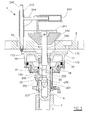
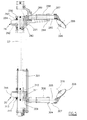
- Figure 4 is a partially interrupted view of the bead release device used by the invention.
- Figure 5 is a vertical section through Figure 4.
- FIGS. 1 and 2 show the tyre removal machine 1, which comprises a lower base 2, from the upper surface of which there projects a shell 3 containing a vertical shaft 16 carrying the means 4 for supporting and locking in position the wheel 5, inclusive of the wheel rim 6 and tyre 7, as shown in Figure 2.
- a vertical column 8 carrying both the support and positioning means for the usual tyre mounting and removal tool 14, known per se, and the bead release device 15 with which the invention is provided.
- the shaft 16 is a rotary shaft supported by a lower moving assembly, not shown, which can translate horizontally within the vertical plane comprising the axis of the tool 14.
- the means 4 for locking the wheel rim 6 comprise a hollow upper-end portion of the shaft 16 with its internal cavity of hexagonal cross-section, to the upper end of which there is fixed a circular plate 17 on which the wheel rim 6 is rested.
- the plate 17 is provided with upper radial grooves 172 and with a lower cylindrical skirt 170, to the free end of which there is fixed a cover 18 which, together with said skirt, defines a chamber 19.
- annular piston 20 provided with a hollow rod 200 sealedly mounted about the shaft 16.
- conduit 201 which feeds compressed air onto the piston 20.
- the rod 200 of the piston 20 supports an external U-shaped pawl 22 which embraces the rod and comprises a central tooth 220.
- the pawl rocks about two projecting pins 23 positioned on the same diametrical axis, and is provided with a tooth 220 which enters into the interior of said hollow shaft 16 via apertures 202 and 160.
- the interior of said hollow shaft 16 receives the bar 240, also of hexagonal cross-section, of a device 24 provided for locking the wheel rim 6 in the working position.
- Said device 24 comprises said bar 240, which is fixed to an upper member 241 to which there is also fixed a locking cone 242, which is mounted about the bar 240.
- the member 241 also comprises an internally hollow handle 243 within which there slides a bar 244, the free end of which carries a vertical sleeve 245 within which a second bar 246 slides.
- the bar 240 is inserted into the hollow shaft 16, and said second bar 246 is positioned in one of the holes 60 intended to receive the bolts by which the wheel rim is fixed to the vehicle.
- the hexagonal cross-section of the bar 240 ensures that when the device 24 is inserted, the lower end of the bar 246 always encounters and becomes inserted in one of the radial grooves 172 present in the circular plate 17.
- the bar 240 comprises annular projections 250 which are upperly flat and lowerly conical, so that when the bar is inserted into the hollow shaft 16 the conical part of the projections causes the pawl 22 to rotate against the action of a leaf spring 25, while at the same time the bar is unable to be withdrawn because the leaf spring maintains the pawl 22 above the upper flat surface of said projections 250.
- the bar 240 is inserted into the hollow shaft 16 until the cone 242 encounters the outer surface of the central hub 61 of the wheel rim 6. At this point by feeding compressed air through the conduit 201 the piston 20 descends against the action of the spring 21. The descent of the piston also determines the lowering of the pawl 22, the tooth 220 of which rests against the flat upper surface of the annular projections 250, and remains locked in position by the action exerted by the leaf spring 25. In this manner the wheel rim 6 becomes locked in the working position.
- the wheel rim is released by simply releasing the compressed air from the operating chamber 19. In this manner the spring 21 causes the piston 20 and the pawl 22 to rise, this latter, by its rotation, disengaging from the annular projection 250.
- the bead release device comprises a vertical shaft 27, of square or otherwise non-circular cross-section, supported between the plates 80 and 81, which are rigid with the column 8 and with the machine base respectively.
- the shaft 27 can rotate about its axis, being driven by an actuator, not shown but of known type.
- the upper unit 28 comprises a frame 282 having a lateral plate 283 from which there branch two blocks 284 provided with axial holes within which there slides a bar 285 of non-circular cross-section.
- the bar 285 rotatably carries the bead release disc 286, which is idle about its axis 296 and is maintained in position by a spring, its rotation being measured by the feeler 287.
- the bar is maintained urged inwards (towards the left in Figure 5) by the spring 288 and carries at its opposite end a roller 289 which rests against a profiled block 290, above a projecting cam 291.
- the profiled block 290 is slidable on the shaft 27 and maintained resting against the frame 28 by the spring 292, and can be locked on the shaft 27 by the strangling plate 293 rotated by the air piston 294.
- the air piston 294 is controlled by the feeler 287, which measures the rotation of the bead release disc 286 when this rests against the tyre bead.
- the unit 30 is identical to the unit 28, and is disposed inverted thereto at the lower end of the shaft 27.
- the components of the unit 30 are identified by the numbers from 301 to 316, corresponding to the numbers from 281 to 296 of the corresponding components of the unit 28.
- the units 28 and 30 are maintained at their respective ends of the shaft 27 by the cylinder-piston units 281 and 301 respectively.
- the support and positioning means 11 for the usual tool 14 comprise a horizontal guide sleeve 9, which is fixed to the plate 80 rigid with the column 8, and to the interior of which the profiled bar 10 is fixed. It should be noted that the horizontal axis of the bar 10 intersects the central vertical axis of said means 4 for supporting the wheel 5 and locking it in position.
- a programmed electronic processor unit coordinates the movement of certain of the aforedescribed devices as will be apparent hereinafter.
- the operator places the wheel rim 6 complete with tyre 7 on the plate 17 in an approximately centered position.
- the locking bar is arranged to rotate the wheel rim, which remains secured both upperly and lowerly.
- the operator feeds the wheel rim dimensions to the processor, which then causes the shaft 16 to translate until it reaches a zero position in which the bead release discs 286 and 306 lie just outside the flange on the wheel rim.
- the processor causes the shaft 27 to rotate such that the axes 296 and 316 of rotation of the bead release discs 286 and 306 cut the axis of the shaft 16.
- the machine is thus ready to release the bead and possibly remove the tyre in a completely automatic manner.
- the operator has only to feed compressed air to the two cylinder-piston units 281 and 301, which cause the units 28 and 30 to approach the wheel from both sides of it.
- the rear roller 289 of the profiled bar 285 rises along the cam 291 to compel the bar to slide slightly forwards to insert the disc 286 slightly below the wheel rim flange, and act exactly on the wheel tyre.
- the tyre is removed in the normal manner by the tool 14, which is lowered manually into position and locked with usual means by the operator.
Landscapes
- Engineering & Computer Science (AREA)
- Mechanical Engineering (AREA)
- Testing Of Balance (AREA)
- Tyre Moulding (AREA)
- Moulds For Moulding Plastics Or The Like (AREA)
Priority Applications (2)
| Application Number | Priority Date | Filing Date | Title |
|---|---|---|---|
| DE20121433U DE20121433U1 (de) | 2000-05-22 | 2001-04-17 | Automatische Wulstabdrückvorrichtung für Reifenabziehmaschinen und damit ausgestattete Reifenabziehmaschinen |
| DE60129375.4T DE60129375T3 (de) | 2000-05-22 | 2001-04-17 | Reifenabdrückvorrichtung für ein Raddemontiergerät, und Raddemontiergerät mit einer solchen Vorrichtung |
Applications Claiming Priority (2)
| Application Number | Priority Date | Filing Date | Title |
|---|---|---|---|
| ITRE000052 | 2000-05-22 | ||
| IT2000RE000052A IT1319468B1 (it) | 2000-05-22 | 2000-05-22 | Dispositivo stallonatore automatico per macchine smontagomme, emacchine smontagomme cosi' attrezzate |
Publications (4)
| Publication Number | Publication Date |
|---|---|
| EP1157860A2 true EP1157860A2 (fr) | 2001-11-28 |
| EP1157860A3 EP1157860A3 (fr) | 2002-12-18 |
| EP1157860B1 EP1157860B1 (fr) | 2007-07-18 |
| EP1157860B2 EP1157860B2 (fr) | 2013-11-13 |
Family
ID=11453927
Family Applications (1)
| Application Number | Title | Priority Date | Filing Date |
|---|---|---|---|
| EP01201385.0A Expired - Lifetime EP1157860B2 (fr) | 2000-05-22 | 2001-04-17 | Appareil de briseur de talons d'une machine de démontage de pneumatiques, et machine de démontage de pneumatiques équipée avec celui-ci |
Country Status (6)
| Country | Link |
|---|---|
| US (1) | US6527032B2 (fr) |
| EP (1) | EP1157860B2 (fr) |
| JP (1) | JP2002029231A (fr) |
| DE (1) | DE60129375T3 (fr) |
| ES (1) | ES2287068T5 (fr) |
| IT (1) | IT1319468B1 (fr) |
Cited By (17)
| Publication number | Priority date | Publication date | Assignee | Title |
|---|---|---|---|---|
| EP1366933A3 (fr) * | 2002-05-29 | 2004-05-26 | BUTLER ENGINEERING & MARKETING S.r.l. | Machine de montage de pneumatiques et de décoincement des bourrelets |
| EP1607247A1 (fr) * | 2004-06-15 | 2005-12-21 | CORGHI S.p.A. | Dispositif décoinceur de talons |
| EP1946946A1 (fr) * | 2007-01-18 | 2008-07-23 | Societa' Italiana Costruzioni Elettromeccaniche- S.I.C.E.-S.p.A. | Machine de montage/démontage de pneu |
| EP2484541A1 (fr) | 2011-02-08 | 2012-08-08 | CORGHI S.p.A. | Appareil de changement de pneus et procédé pour enlever un pneu d'une jante de roue correspondante |
| ITBI20120002A1 (it) * | 2012-03-03 | 2013-09-04 | S C S R L | Macchina per il montaggio e lo smontaggio di pneumatici di ruote per veicoli |
| EP2634016A1 (fr) * | 2010-02-17 | 2013-09-04 | Snap-on Equipment Srl a unico socio | Démonte-pneu et procédé de mesure des variations de force agissant entre la surface périphérique dýun ensemble roue/pneu et d'un roulement |
| CN104228494A (zh) * | 2014-09-04 | 2014-12-24 | 营口天辅铝业有限公司 | 一种摩托车轮胎拆装机的免大盘旋转三爪气动夹紧装置 |
| ITMO20130275A1 (it) * | 2013-09-30 | 2015-03-31 | Sicam Srl | Macchina smontagomme |
| CN105150782A (zh) * | 2015-09-30 | 2015-12-16 | 池学建 | 拆胎机及其拆胎方法 |
| EP3000628A1 (fr) * | 2014-09-26 | 2016-03-30 | Bright Technology Co., Ltd. | Bras d'assistant pour changeur de pneus d'automobile et procédé de fabrication de pièces principales du bras auxiliaire |
| CN106042795A (zh) * | 2015-04-03 | 2016-10-26 | 古丽亚诺集团股份公司 | 用于安装和拆卸车辆的车轮轮胎的机器 |
| IT201900005728A1 (it) | 2019-04-12 | 2020-10-12 | Nexion Spa | Apparato smontagomme |
| IT202100001235A1 (it) | 2021-01-25 | 2022-07-25 | Snap On Equip Srl Unico Socio | Apparato smontagomme con utensile a basculamento automatico |
| IT202100001238A1 (it) | 2021-01-25 | 2022-07-25 | Snap On Equip Srl Unico Socio | Apparato smontagomme |
| KR20220107739A (ko) * | 2021-01-26 | 2022-08-02 | 조영진 | 타이어 탈착용 고정장치 |
| IT202100005828A1 (it) * | 2021-03-12 | 2022-09-12 | Butler Eng And Marketing S P A Abbreviabile In Butler S P A | Apparecchiatura smontagomme e procedimento per il montaggio e smontaggio di pneumatici |
| US11712932B2 (en) | 2020-02-13 | 2023-08-01 | Butler Engineering and Marketing S.p.A. (Butler S.p.A.) | Apparatus and process for the assembly and disassembly of tires |
Families Citing this family (40)
| Publication number | Priority date | Publication date | Assignee | Title |
|---|---|---|---|---|
| IT1319475B1 (it) * | 2000-08-03 | 2003-10-10 | Corghi Spa | Dispositivo automatico per lo smontaggio ed il montaggio deipneumatici, e macchine smontagomme cosi' attrezzate |
| US20040140059A1 (en) * | 2003-01-17 | 2004-07-22 | John Lewis Wagner | Portable tire bead breaker |
| ITVR20050059A1 (it) * | 2005-05-16 | 2006-11-17 | Butler Eng & Marketing | Gruppo di supporto e rotazione di un cerchione in particolare per una macchina monta-smontagomme. |
| ITRE20050016U1 (it) * | 2005-05-17 | 2006-11-18 | Corghi Spa | Attrezzo perfezionato per agevolare il montaggio del pneumatico sul cerchione |
| US20080289772A1 (en) * | 2005-06-06 | 2008-11-27 | Reeves Jr William Manning | Method and Apparatus For Mounting a Tire |
| ITRE20050079A1 (it) * | 2005-07-11 | 2007-01-12 | Corghi Spa | Metodo e dispositivo per lo smontaggio di pneumatici autoportanti |
| US7621311B2 (en) * | 2005-10-05 | 2009-11-24 | Android Industries Llc | Tire-wheel assembly adjuster |
| US7343955B2 (en) | 2005-12-28 | 2008-03-18 | Hennessy Industries, Inc. | Tire changing machine |
| US7438109B2 (en) * | 2005-12-30 | 2008-10-21 | Hennessy Industries, Inc. | Tire changer |
| EP1996518B1 (fr) | 2006-03-20 | 2011-09-14 | Council of Scientific & Industrial Research | Appareil de filtration et de désinfection d'eau de mer/de ballast de navire et procédé s'y rapportant |
| USD614679S1 (en) * | 2006-04-26 | 2010-04-27 | Corghi S.P.A. | Tire dismounter |
| ITMO20060398A1 (it) * | 2006-12-04 | 2008-06-05 | Gino Ferrari | Apparato per macchine smontagomme |
| DE102007057484B3 (de) * | 2007-11-29 | 2009-06-18 | Snap-On Equipment S.R.L A Unico Socio, Correggio | Reifenmontiermaschine |
| US8770254B1 (en) | 2008-07-17 | 2014-07-08 | Hunter Engineering Company | Tire changer with rotational position and tracking control |
| US8613303B1 (en) * | 2008-07-17 | 2013-12-24 | Hunter Engineering Company | Tire changing machine with force detection and control methods |
| US8985178B1 (en) | 2010-04-23 | 2015-03-24 | Hunter Engineering Company | Tire bead breaker device and methods for automated tire changer machine |
| US8307874B1 (en) | 2008-01-25 | 2012-11-13 | Hunter Engineering Company | Tire changing method and machine with angularly positionable drive axis |
| JP5563742B2 (ja) * | 2008-03-19 | 2014-07-30 | 小野谷機工株式会社 | タイヤ着脱装置のマウントプレス装置 |
| ES2356039T3 (es) * | 2008-04-17 | 2011-04-04 | Snap-On Equipment Srl A Unico Socio | Procedimiento y aparato para montar y desmontar un neumático de vehículo a motor. |
| US9073394B1 (en) | 2008-07-17 | 2015-07-07 | Hunter Engineering Company | Tire changing machine with force detection and control methods |
| IT1394417B1 (it) * | 2009-05-18 | 2012-06-15 | Teco Srl | Utensile per macchine smontagomme |
| IT1395311B1 (it) * | 2009-05-19 | 2012-09-05 | Butler Eng & Marketing | Gruppo stallonatore per macchina monta-smontagomme |
| IT1395185B1 (it) * | 2009-08-07 | 2012-09-05 | Giuliano S P A Ora Giuliano Group S P A | Gruppo per la stallonatura di pneumatici in macchine smontagomme o simili |
| US8443865B2 (en) * | 2009-08-21 | 2013-05-21 | Hennessy Industries, Inc. | Wheel clamping apparatus and method |
| US8573918B2 (en) * | 2009-08-26 | 2013-11-05 | Android Industries Llc | Dual mode end effector |
| ATE551212T1 (de) * | 2010-01-20 | 2012-04-15 | Snap On Equip Srl Unico Socio | Verfahren zur befestigung eines reifen an einer felge zum erhalten eines fahrzeugrades und verfahren zur demontage eines reifens von einer felge sowie vorrichtung dafür |
| US20130192768A1 (en) * | 2012-01-31 | 2013-08-01 | Chih-Liang Peng | Structure of tire changer |
| CN102910043B (zh) * | 2012-11-05 | 2015-07-29 | 张立安 | 一种全自动扒胎装胎机 |
| US9061555B2 (en) * | 2013-01-25 | 2015-06-23 | Dominion Technologies Group, Inc. | Method and machine for automated tire and wheel assembly |
| JP2015212110A (ja) * | 2014-05-01 | 2015-11-26 | 株式会社オルタライフ | タイヤ支持機構及びタイヤチェンジャ |
| EP3501862B1 (fr) | 2014-05-30 | 2022-08-03 | Snap-on Equipment Srl a unico socio | Procédé de montage et de démontage d'un pneumatique sur une jante de roue |
| EP2965927B1 (fr) * | 2014-07-03 | 2016-07-20 | CORGHI S.p.A. | Machine et procédé pour le montage et le démontage d'un pneumatique |
| ES2616537T3 (es) * | 2014-07-03 | 2017-06-13 | Corghi S.P.A. | Máquina y método para montar y desmontar un neumático |
| CN105329051B (zh) * | 2014-07-07 | 2017-05-17 | 营口光明科技有限公司 | 一种轮胎分离机构及拆胎机 |
| ES2620974T3 (es) * | 2015-03-12 | 2017-06-30 | Corghi S.P.A. | Máquina de servicio de ruedas y método para bloquear una rueda a una unidad de soporte de ruedas |
| IT201600071778A1 (it) * | 2016-07-08 | 2018-01-08 | Butler Eng And Marketing S P A | Gruppo di stallonamento di una ruota gommata e/o di spinta di una porzione di un pneumatico di una ruota gommata |
| CN107856482B (zh) * | 2017-11-16 | 2023-06-06 | 营口大力汽保设备科技有限公司 | 一种拆胎机 |
| CN111823793B (zh) * | 2020-06-30 | 2022-05-17 | 广州赫力汽车维修设备有限公司 | 一种轮胎拆装机构及轮胎拆装机 |
| CN114179572B (zh) * | 2021-12-27 | 2022-08-23 | 伺轮智能机器人(南京)有限公司 | 用于锁定轮辋或车轮的锁紧头和快速锁紧装置 |
| US12220950B2 (en) * | 2022-06-07 | 2025-02-11 | Xiamen Lenco Co., Ltd. | Tire mounting apparatus |
Family Cites Families (11)
| Publication number | Priority date | Publication date | Assignee | Title |
|---|---|---|---|---|
| US3168130A (en) † | 1963-08-20 | 1965-02-02 | Eugene W Turpin | Wheel supporting and tire dismounting apparatus |
| DE2529343C3 (de) † | 1975-07-01 | 1981-07-09 | Gebr. Hofmann Gmbh & Co Kg Maschinenfabrik, 6100 Darmstadt | Vorrichtung zum Montieren und Demontieren von Kraftfahrzeugreifen, insbesondere für Lastkraftwagen |
| JPS5373703A (en) * | 1976-12-10 | 1978-06-30 | Sugiyasu Kikai Kougiyou Kk | Tire replacing apparatus for vehicle wheel |
| DE3168448D1 (en) † | 1980-06-12 | 1985-03-07 | Gs Srl | A machine for the removal and fitting of pneumatic tyres |
| IT1243660B (it) * | 1990-10-22 | 1994-06-16 | Corghi Spa | Macchina smontagomme con autrocentrante reclinabile. |
| US5226465A (en) * | 1991-02-19 | 1993-07-13 | Stahlgruber Otto Gruber Gmbh & Co. | Mounting device for motor vehicle tires |
| EP0499825B1 (fr) * | 1991-02-19 | 1994-04-13 | STAHLGRUBER Otto Gruber GmbH & Co. | Dispositif de démontage de pneumatique de véhicules automobiles |
| IT230998Y1 (it) * | 1993-05-21 | 1999-07-05 | Corghi Spa | dispositivo stallonatore per macchine smontagomme. |
| WO1999042309A1 (fr) * | 1998-02-20 | 1999-08-26 | Aim Automotive Integrated Manufacturing, Inc. | Robot et procede d'assemblage d'un pneu a une jante |
| US6176288B1 (en) * | 1998-07-22 | 2001-01-23 | Aim Automotive Integrated Manufacturing, Inc. | Passive angular orientation inflation head for inflating a tire mounted on a wheel |
| IT1309353B1 (it) * | 1999-04-02 | 2002-01-22 | Butler Eng & Marketing | Macchina monta-smontagomme per ruote di veicoli industriali. |
-
2000
- 2000-05-22 IT IT2000RE000052A patent/IT1319468B1/it active
-
2001
- 2001-04-17 DE DE60129375.4T patent/DE60129375T3/de not_active Expired - Lifetime
- 2001-04-17 EP EP01201385.0A patent/EP1157860B2/fr not_active Expired - Lifetime
- 2001-04-17 ES ES01201385.0T patent/ES2287068T5/es not_active Expired - Lifetime
- 2001-04-30 US US09/843,697 patent/US6527032B2/en not_active Expired - Lifetime
- 2001-05-22 JP JP2001152367A patent/JP2002029231A/ja active Pending
Non-Patent Citations (1)
| Title |
|---|
| None |
Cited By (36)
| Publication number | Priority date | Publication date | Assignee | Title |
|---|---|---|---|---|
| EP1366933A3 (fr) * | 2002-05-29 | 2004-05-26 | BUTLER ENGINEERING & MARKETING S.r.l. | Machine de montage de pneumatiques et de décoincement des bourrelets |
| US6886619B2 (en) | 2002-05-29 | 2005-05-03 | Butler Engineering & Marketing Srl | Tire assembling-release machine |
| EP1607247A1 (fr) * | 2004-06-15 | 2005-12-21 | CORGHI S.p.A. | Dispositif décoinceur de talons |
| JP2006001538A (ja) * | 2004-06-15 | 2006-01-05 | Corghi Spa | ビードブレーカー装置 |
| US7108035B2 (en) | 2004-06-15 | 2006-09-19 | Corghi S.P.A. | Bead breaker device |
| EP1946946A1 (fr) * | 2007-01-18 | 2008-07-23 | Societa' Italiana Costruzioni Elettromeccaniche- S.I.C.E.-S.p.A. | Machine de montage/démontage de pneu |
| US7703497B2 (en) | 2007-01-18 | 2010-04-27 | Societa Italiana Costruzioni Elettromeccaniche S.I.C.E. S.P.A. | Tyre mounting/dismounting machine |
| CN101224696B (zh) * | 2007-01-18 | 2011-06-08 | 意大利电气机械建筑协会股份公司 | 轮胎安装/拆卸设备 |
| US9834047B2 (en) | 2010-02-17 | 2017-12-05 | Snap-On Equipment Srl A Unico Socio | Tire changer and method of measuring force variations |
| EP2634016A1 (fr) * | 2010-02-17 | 2013-09-04 | Snap-on Equipment Srl a unico socio | Démonte-pneu et procédé de mesure des variations de force agissant entre la surface périphérique dýun ensemble roue/pneu et d'un roulement |
| US9114676B2 (en) | 2010-02-17 | 2015-08-25 | Snap-On Equipment Srl A Unico Socio | Tire changer and method of measuring force variations |
| ITBO20110054A1 (it) * | 2011-02-08 | 2012-08-09 | Corghi Spa | Apparato e metodo per lo smontaggio di uno pneumatico da un corrispondente cerchione di una ruota. |
| EP2484541A1 (fr) | 2011-02-08 | 2012-08-08 | CORGHI S.p.A. | Appareil de changement de pneus et procédé pour enlever un pneu d'une jante de roue correspondante |
| US9662946B2 (en) | 2011-02-08 | 2017-05-30 | Corghi S.P.A. | Tyre changing apparatus and method for removing a tyre from a corresponding wheel rim |
| ITBI20120002A1 (it) * | 2012-03-03 | 2013-09-04 | S C S R L | Macchina per il montaggio e lo smontaggio di pneumatici di ruote per veicoli |
| ITMO20130275A1 (it) * | 2013-09-30 | 2015-03-31 | Sicam Srl | Macchina smontagomme |
| WO2015044920A1 (fr) * | 2013-09-30 | 2015-04-02 | Sicam S.R.L. | Machine de changement de pneu |
| CN104228494B (zh) * | 2014-09-04 | 2016-09-07 | 营口天辅铝业有限公司 | 一种摩托车轮胎拆装机的免大盘旋转三爪气动夹紧装置 |
| CN104228494A (zh) * | 2014-09-04 | 2014-12-24 | 营口天辅铝业有限公司 | 一种摩托车轮胎拆装机的免大盘旋转三爪气动夹紧装置 |
| EP3000628A1 (fr) * | 2014-09-26 | 2016-03-30 | Bright Technology Co., Ltd. | Bras d'assistant pour changeur de pneus d'automobile et procédé de fabrication de pièces principales du bras auxiliaire |
| US9802448B2 (en) | 2014-09-26 | 2017-10-31 | Corwei (Yingkou) Industrial Co., Ltd. | Assistant arm for automobile tire changer and method for manufacturing principal parts of the assistant arm |
| CN106042795A (zh) * | 2015-04-03 | 2016-10-26 | 古丽亚诺集团股份公司 | 用于安装和拆卸车辆的车轮轮胎的机器 |
| CN105150782A (zh) * | 2015-09-30 | 2015-12-16 | 池学建 | 拆胎机及其拆胎方法 |
| IT201900005728A1 (it) | 2019-04-12 | 2020-10-12 | Nexion Spa | Apparato smontagomme |
| US12337623B2 (en) | 2019-04-12 | 2025-06-24 | Nexion S.P.A. | Tyre changing apparatus |
| US11712932B2 (en) | 2020-02-13 | 2023-08-01 | Butler Engineering and Marketing S.p.A. (Butler S.p.A.) | Apparatus and process for the assembly and disassembly of tires |
| EP4032730A1 (fr) | 2021-01-25 | 2022-07-27 | Snap-on Equipment Srl a unico socio | Appareil à démontage de pneumatique |
| EP4032729A1 (fr) | 2021-01-25 | 2022-07-27 | Snap-on Equipment Srl a unico socio | Appareil de démontage de pneu doté d'un outil à pivotement automatique |
| IT202100001238A1 (it) | 2021-01-25 | 2022-07-25 | Snap On Equip Srl Unico Socio | Apparato smontagomme |
| US12070973B2 (en) | 2021-01-25 | 2024-08-27 | Snap-On Equipment Srl A Unico Socio | Tyre-removal apparatus |
| US12233673B2 (en) | 2021-01-25 | 2025-02-25 | Snap-On Equipment Srl A Unico Socio | Tyre-removal apparatus with automatically pivoting tool |
| IT202100001235A1 (it) | 2021-01-25 | 2022-07-25 | Snap On Equip Srl Unico Socio | Apparato smontagomme con utensile a basculamento automatico |
| KR20220107739A (ko) * | 2021-01-26 | 2022-08-02 | 조영진 | 타이어 탈착용 고정장치 |
| IT202100005828A1 (it) * | 2021-03-12 | 2022-09-12 | Butler Eng And Marketing S P A Abbreviabile In Butler S P A | Apparecchiatura smontagomme e procedimento per il montaggio e smontaggio di pneumatici |
| EP4067121A1 (fr) | 2021-03-12 | 2022-10-05 | Butler Engineering and Marketing S.p.A. Abbreviabile in "Butler S.p.A." | Appareil de changement de pneus et procédé de montage et de démontage de pneus |
| US12172474B2 (en) | 2021-03-12 | 2024-12-24 | Vehicle Service Group Italy S.R.L. | Tire changer apparatus |
Also Published As
| Publication number | Publication date |
|---|---|
| DE60129375T2 (de) | 2008-04-17 |
| EP1157860B1 (fr) | 2007-07-18 |
| DE60129375T3 (de) | 2014-04-10 |
| IT1319468B1 (it) | 2003-10-10 |
| EP1157860B2 (fr) | 2013-11-13 |
| JP2002029231A (ja) | 2002-01-29 |
| US20010042601A1 (en) | 2001-11-22 |
| DE60129375D1 (de) | 2007-08-30 |
| ES2287068T5 (es) | 2014-02-24 |
| ITRE20000052A1 (it) | 2001-11-22 |
| US6527032B2 (en) | 2003-03-04 |
| EP1157860A3 (fr) | 2002-12-18 |
| ES2287068T3 (es) | 2007-12-16 |
Similar Documents
| Publication | Publication Date | Title |
|---|---|---|
| US6527032B2 (en) | Automatic bead release device for tire removal machines, and tire removal machines equipped therewith | |
| US6619362B2 (en) | Automatic tyre removal and mounting device and tyre removal machines equipped therewith | |
| EP1157861B1 (fr) | Dispositif de verrouillage de jante de roue pour une machine de démontage de pneus | |
| EP1314584B1 (fr) | Tête de décoincement et de démontage du bourrelet pour machine de montage de pneumatiques | |
| EP2629992B1 (fr) | Machine de démontage de pneu | |
| US4173245A (en) | Apparatus for mounting and dismounting vehicle tires | |
| EP1459913B1 (fr) | Dispositif de montage et démontage de pneumatiques | |
| EP2524819B1 (fr) | Unité de démonte-talons pour machines de changement de pneus | |
| US3255800A (en) | Tire changing stand | |
| US5088539A (en) | Tire changing apparatus | |
| US5836368A (en) | Machine for mounting and removing tires onto and from respective wheel rims | |
| US3877505A (en) | Upper bead breaker mechanism | |
| EP1844959B1 (fr) | Procédé et machine pour enlever un pneu équipé d'un anneau de roulage à plat interne rigide | |
| EP0015102A1 (fr) | Dispositif dégage-talon pour une machine à changer les pneumatiques | |
| CN105984294B (zh) | 一种用于轮胎拆装机的操作头 | |
| EP2756969B1 (fr) | Machine destinée à démonter des pneus de jantes de véhicules ou destinée à monter des pneus sur une jante de véhicule | |
| EP0624486A1 (fr) | Machine pour monter un pneu sur une roue | |
| CN213766541U (zh) | 一种用于珍珠制品的打孔装置 | |
| EP1724129B1 (fr) | Dispositif de décoincement du talon d'un pneumatique d'une roue montée sur le plateau tournant d'une machine de démontage de pneumatiques. | |
| EP1236589A2 (fr) | Dispositif amélioré pour le montage et le démontage de pneus avec appui de sécurité du type "system pax" et similaires | |
| JP2518503Y2 (ja) | ブレーキシューストリッパーのフィクスチュア装置 | |
| WO2022269499A1 (fr) | Machine à changer les pneus, en particulier pour grandes roues | |
| JPH06198380A (ja) | ブレーキシューストリッパー |
Legal Events
| Date | Code | Title | Description |
|---|---|---|---|
| PUAI | Public reference made under article 153(3) epc to a published international application that has entered the european phase |
Free format text: ORIGINAL CODE: 0009012 |
|
| AK | Designated contracting states |
Kind code of ref document: A2 Designated state(s): AT BE CH CY DE DK ES FI FR GB GR IE IT LI LU MC NL PT SE TR |
|
| AX | Request for extension of the european patent |
Free format text: AL;LT;LV;MK;RO;SI |
|
| PUAL | Search report despatched |
Free format text: ORIGINAL CODE: 0009013 |
|
| AK | Designated contracting states |
Kind code of ref document: A3 Designated state(s): AT BE CH CY DE DK ES FI FR GB GR IE IT LI LU MC NL PT SE TR |
|
| AX | Request for extension of the european patent |
Free format text: AL;LT;LV;MK;RO;SI |
|
| RIC1 | Information provided on ipc code assigned before grant |
Free format text: 7B 60C 25/13 A, 7B 60C 25/132 B, 7B 60C 25/138 B |
|
| 17P | Request for examination filed |
Effective date: 20030321 |
|
| AKX | Designation fees paid |
Designated state(s): DE ES FR IT |
|
| GRAP | Despatch of communication of intention to grant a patent |
Free format text: ORIGINAL CODE: EPIDOSNIGR1 |
|
| GRAS | Grant fee paid |
Free format text: ORIGINAL CODE: EPIDOSNIGR3 |
|
| GRAA | (expected) grant |
Free format text: ORIGINAL CODE: 0009210 |
|
| AK | Designated contracting states |
Kind code of ref document: B1 Designated state(s): DE ES FR IT |
|
| REF | Corresponds to: |
Ref document number: 60129375 Country of ref document: DE Date of ref document: 20070830 Kind code of ref document: P |
|
| ET | Fr: translation filed | ||
| REG | Reference to a national code |
Ref country code: ES Ref legal event code: FG2A Ref document number: 2287068 Country of ref document: ES Kind code of ref document: T3 |
|
| PLBI | Opposition filed |
Free format text: ORIGINAL CODE: 0009260 |
|
| 26 | Opposition filed |
Opponent name: SNAP-ON EQUIPMENT GMBH Effective date: 20080418 |
|
| PLAX | Notice of opposition and request to file observation + time limit sent |
Free format text: ORIGINAL CODE: EPIDOSNOBS2 |
|
| PLBB | Reply of patent proprietor to notice(s) of opposition received |
Free format text: ORIGINAL CODE: EPIDOSNOBS3 |
|
| APAH | Appeal reference modified |
Free format text: ORIGINAL CODE: EPIDOSCREFNO |
|
| APBM | Appeal reference recorded |
Free format text: ORIGINAL CODE: EPIDOSNREFNO |
|
| APBP | Date of receipt of notice of appeal recorded |
Free format text: ORIGINAL CODE: EPIDOSNNOA2O |
|
| APBM | Appeal reference recorded |
Free format text: ORIGINAL CODE: EPIDOSNREFNO |
|
| APBP | Date of receipt of notice of appeal recorded |
Free format text: ORIGINAL CODE: EPIDOSNNOA2O |
|
| APBQ | Date of receipt of statement of grounds of appeal recorded |
Free format text: ORIGINAL CODE: EPIDOSNNOA3O |
|
| REG | Reference to a national code |
Ref country code: DE Ref legal event code: R082 Ref document number: 60129375 Country of ref document: DE Representative=s name: VON ROHR PATENTANWAELTE PARTNERSCHAFT MBB, DE Ref country code: DE Ref legal event code: R082 Ref document number: 60129375 Country of ref document: DE Representative=s name: VON ROHR PATENTANWAELTE PARTNERSCHAFT, DE |
|
| APBU | Appeal procedure closed |
Free format text: ORIGINAL CODE: EPIDOSNNOA9O |
|
| PUAH | Patent maintained in amended form |
Free format text: ORIGINAL CODE: 0009272 |
|
| STAA | Information on the status of an ep patent application or granted ep patent |
Free format text: STATUS: PATENT MAINTAINED AS AMENDED |
|
| 27A | Patent maintained in amended form |
Effective date: 20131113 |
|
| AK | Designated contracting states |
Kind code of ref document: B2 Designated state(s): DE ES FR IT |
|
| REG | Reference to a national code |
Ref country code: DE Ref legal event code: R102 Ref document number: 60129375 Country of ref document: DE Effective date: 20131113 |
|
| REG | Reference to a national code |
Ref country code: ES Ref legal event code: DC2A Ref document number: 2287068 Country of ref document: ES Kind code of ref document: T5 Effective date: 20140224 |
|
| REG | Reference to a national code |
Ref country code: FR Ref legal event code: PLFP Year of fee payment: 16 |
|
| REG | Reference to a national code |
Ref country code: FR Ref legal event code: PLFP Year of fee payment: 17 |
|
| REG | Reference to a national code |
Ref country code: DE Ref legal event code: R082 Ref document number: 60129375 Country of ref document: DE Representative=s name: VON ROHR PATENTANWAELTE PARTNERSCHAFT MBB, DE Ref country code: DE Ref legal event code: R081 Ref document number: 60129375 Country of ref document: DE Owner name: NEXION S.P.A., IT Free format text: FORMER OWNER: CORGHI S.P.A., CORREGGIO, REGGIO EMILIA, IT |
|
| REG | Reference to a national code |
Ref country code: FR Ref legal event code: PLFP Year of fee payment: 18 |
|
| REG | Reference to a national code |
Ref country code: ES Ref legal event code: PC2A Owner name: NEXION S.P.A. Effective date: 20180529 Ref country code: ES Ref legal event code: PC2A Effective date: 20180529 |
|
| REG | Reference to a national code |
Ref country code: FR Ref legal event code: CD Owner name: NEXION S.P.A., IT Effective date: 20180620 |
|
| PGFP | Annual fee paid to national office [announced via postgrant information from national office to epo] |
Ref country code: ES Payment date: 20200511 Year of fee payment: 20 Ref country code: FR Payment date: 20200429 Year of fee payment: 20 Ref country code: DE Payment date: 20200430 Year of fee payment: 20 |
|
| PGFP | Annual fee paid to national office [announced via postgrant information from national office to epo] |
Ref country code: IT Payment date: 20200420 Year of fee payment: 20 |
|
| REG | Reference to a national code |
Ref country code: DE Ref legal event code: R071 Ref document number: 60129375 Country of ref document: DE |
|
| REG | Reference to a national code |
Ref country code: ES Ref legal event code: FD2A Effective date: 20210726 |
|
| PG25 | Lapsed in a contracting state [announced via postgrant information from national office to epo] |
Ref country code: ES Free format text: LAPSE BECAUSE OF EXPIRATION OF PROTECTION Effective date: 20210418 |