EP1158187A1 - Mutter mit Federvorrichtung - Google Patents
Mutter mit Federvorrichtung Download PDFInfo
- Publication number
- EP1158187A1 EP1158187A1 EP01120005A EP01120005A EP1158187A1 EP 1158187 A1 EP1158187 A1 EP 1158187A1 EP 01120005 A EP01120005 A EP 01120005A EP 01120005 A EP01120005 A EP 01120005A EP 1158187 A1 EP1158187 A1 EP 1158187A1
- Authority
- EP
- European Patent Office
- Prior art keywords
- nut
- bore
- fitting piece
- bolt
- nut body
- Prior art date
- Legal status (The legal status is an assumption and is not a legal conclusion. Google has not performed a legal analysis and makes no representation as to the accuracy of the status listed.)
- Withdrawn
Links
- 238000003780 insertion Methods 0.000 claims abstract description 17
- 230000037431 insertion Effects 0.000 claims abstract description 17
- 238000003466 welding Methods 0.000 claims description 4
- 239000000853 adhesive Substances 0.000 claims description 2
- 230000001070 adhesive effect Effects 0.000 claims description 2
- 239000000463 material Substances 0.000 claims description 2
- 229920003002 synthetic resin Polymers 0.000 claims description 2
- 239000000057 synthetic resin Substances 0.000 claims description 2
- 230000008602 contraction Effects 0.000 description 1
- 238000007796 conventional method Methods 0.000 description 1
- 238000009434 installation Methods 0.000 description 1
- 238000000465 moulding Methods 0.000 description 1
- 230000003014 reinforcing effect Effects 0.000 description 1
Images








Classifications
-
- E—FIXED CONSTRUCTIONS
- E04—BUILDING
- E04B—GENERAL BUILDING CONSTRUCTIONS; WALLS, e.g. PARTITIONS; ROOFS; FLOORS; CEILINGS; INSULATION OR OTHER PROTECTION OF BUILDINGS
- E04B1/00—Constructions in general; Structures which are not restricted either to walls, e.g. partitions, or floors or ceilings or roofs
- E04B1/18—Structures comprising elongated load-supporting parts, e.g. columns, girders, skeletons
- E04B1/26—Structures comprising elongated load-supporting parts, e.g. columns, girders, skeletons the supporting parts consisting of wood
- E04B1/2604—Connections specially adapted therefor
-
- F—MECHANICAL ENGINEERING; LIGHTING; HEATING; WEAPONS; BLASTING
- F16—ENGINEERING ELEMENTS AND UNITS; GENERAL MEASURES FOR PRODUCING AND MAINTAINING EFFECTIVE FUNCTIONING OF MACHINES OR INSTALLATIONS; THERMAL INSULATION IN GENERAL
- F16B—DEVICES FOR FASTENING OR SECURING CONSTRUCTIONAL ELEMENTS OR MACHINE PARTS TOGETHER, e.g. NAILS, BOLTS, CIRCLIPS, CLAMPS, CLIPS OR WEDGES; JOINTS OR JOINTING
- F16B37/00—Nuts or like thread-engaging members
- F16B37/08—Quickly-detachable or mountable nuts, e.g. consisting of two or more parts; Nuts movable along the bolt after tilting the nut
- F16B37/0807—Nuts engaged from the end of the bolt, e.g. axially slidable nuts
- F16B37/0857—Nuts engaged from the end of the bolt, e.g. axially slidable nuts with the threaded portions of the nut engaging the thread of the bolt by the action of one or more springs or resilient retaining members
-
- E—FIXED CONSTRUCTIONS
- E04—BUILDING
- E04B—GENERAL BUILDING CONSTRUCTIONS; WALLS, e.g. PARTITIONS; ROOFS; FLOORS; CEILINGS; INSULATION OR OTHER PROTECTION OF BUILDINGS
- E04B1/00—Constructions in general; Structures which are not restricted either to walls, e.g. partitions, or floors or ceilings or roofs
- E04B1/18—Structures comprising elongated load-supporting parts, e.g. columns, girders, skeletons
- E04B1/26—Structures comprising elongated load-supporting parts, e.g. columns, girders, skeletons the supporting parts consisting of wood
- E04B1/2604—Connections specially adapted therefor
- E04B2001/2652—Details of nailing, screwing, or bolting
Definitions
- the present invention relates to a nut which is screwed onto a paddle-shaped bolt used where a connection between a beam and another beam in a wooden house is reinforced, or a nut and connector which are used to reinforce a connection between a beam and another beam.
- the nut screwed onto the bolt is released and does not function when the timber material dries and contracts.
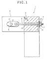
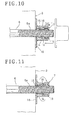
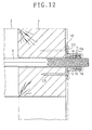
- Figs. 1 to 12 illustrate a first embodiment of the present invention wherein a connector 1, for example shown in Fig. 1, is used for reinforcing a connection between a beam 2 and another beam 3 of a wooden house.
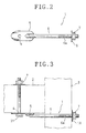
- the connector 1, shown in Figs. 2 and 3, comprises a fitting plate 5, a bolt 6, and a nut 7 of the present invention.
- the fitting plate 5 is formed in the shape of an oval and has an insertion hole 4 for inserting a stopper like a bolt, nail, or the like, in the portion adjacent one end portion thereof.
- the bolt 6 is fixed to a portion adjacent another end portion of the fitting plate 5.
- a side portion of the bolt 6 is fixed to the end portion by welding and another end portion of the bolt 6 projects outwardly.
- the nut 7 of the present invention can be screwed onto the bolt 6 after it has been pushed onto the bolt 6 to a fixed position.
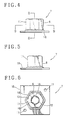
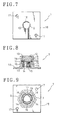
- the nut 7 illustrated in Figs. 4 to 9 has an outer wall 8 formed in the shape of a polygon, for example a hexagonal shape, in each embodiment of the present invention and an inner wall defining a portion of a bore.
- the nut 7 also comprises a nut body 11 with the bore having a tapered bore portion with an inclined inner wall extending from a narrow bore diameter end of the nut body 11 to a large bore diameter end at the inner wall 9.
- a stopper 13 is formed at the large diameter end portion of the bore and defines a bolt insertion hole 12.
- At least three or more guideposts, for example three guideposts 14, 14, 14 in this embodiment, are formed coaxially at the inclined inner wall of the nut body 11.
- Three nut segments 16, 16, 16 are movably disposed among the guideposts 14, 14, 14 to move in a coaxial direction and have screw threads 15 on an inner wall thereof.
- the screw threads 15 screw onto the bolt 6.
- a fitting piece 18 comprises a flange fixed to the narrow bore diameter end of the nut body 11 by welding and has a plurality of screw insertion holes 17, 17 disposed outwardly of an outer circumferential portion of the nut body 11. The fitting piece 18 is used to fix the nut to a beam or the like.
- a spring 19 is located within the nut 11 between the stopper 13 and the three nut segments 16, 16, 16 to bias the nut segments 16, 16, 16 towards the narrow bore diameter end of the nut body 11 via a washer 19a as necessary.
- the bolt insertion holes 20, 20 are formed at a portion that is to be reinforced where first and second beams 2 and 3 are joined. After the bolt 6 is inserted into the bolt insertion hole 20 of the second beam 3, the fitting plate 5 is fixed to the first beam 2 by means of a bolt 21 and nut 7.
- the nut 7 is pushed onto the bolt 6 to a tightening position such that the fitting piece 18 of the nut 7 is seated.
- the nut segments 16, 16, 16 then slide towards the large diameter end of the tapered bore portion against the bias of the spring 19 to permit insertion of bolt 6.
- the nut 7 is tightened using a wrench, or the like, as illustrated in Fig. 11.
- the screw threads 15, 15, 15 of the nut segments 16, 16, 16 are screwed onto the threaded portion 6a of the bolt 6 and the first beam 2 is fixed to the second beam 3.
- 23 are driven in insertion holes 17, 17 of the fitting piece 18, and the fitting piece 18 and beam 3 are fixed together.
- the fitting piece 18 may be fixed by pins in the shape of a hook.
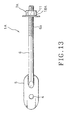
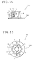
- a second embodiment of the present invention is shown in Figs. 13 to 15. It is distinguished from the first embodiment by the fact that the nut 7 is replaced with another similar nut 7A.
- the nut 7A includes a fitting plate 18A formed in the shape of a disc and fixed to the nut body 11.
- a connector 1A with the nut 7A according to the second embodiment will have similar advantages to that according to the first embodiment.
- a third embodiment of the present invention is shown in Figs. 16 to 18. It is distinguished from the first embodiment by the fact that the nut 7 is replaced with another similar nut 7B.
- the nut 7B includes a fitting piece 18B having screw insertion grooves 24, 24 at an outer circumferential portion thereof. Such a fitting plate may be formed by moulding.
- a connector 1B with the nut 7B according to the third embodiment will have similar advantages to that according to the first embodiment.
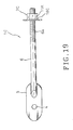
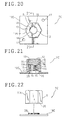
- a fourth embodiment of the present invention is shown in Figs. 19 to 22. It is distinguished from the first embodiment by the fact that a thread portion 25 is formed at an inner wall surface at the narrow bore diameter end of the nut body 11A and a threaded tube 26 on a fitting piece 18C screws into the threaded portion 25.
- a connector 1C with the nut 7C having the fitting piece 18C screwed onto the nut body 11A according to the third embodiment will have similar advantages to that according to the first embodiment.
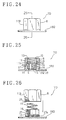
- a fifth embodiment of the present invention is shown in Figs. 23 to 26. It is distinguished from the first embodiment by the fact that the nut 7 is replaced with another similar nut 7D and the nut body 11 is replaced with another similar nut body 11B.
- the nut 7D includes a fitting plate 18D having a tube 27 formed integrally therewith, the tube 27 being provided with a threaded portion 27a on an outer circumferential portion of a lower end thereof which supports the nut segments 16, 16, 16.
- the nut body 11B has a threaded portion 28 which is formed in an inner wall surface of the end portion thereof and screws onto the threaded portion 27a of the tube 27.
- a connector 1D with the nut 7D according to the fifth embodiment will have similar advantages to that according to the first embodiment and the mounting of the nut 7D can be done easily.
- the threaded portion area between the nut body 11 B and fitting piece 18D may be fixed by an adhesive, welding, or the like.
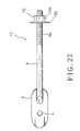
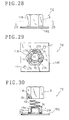
- a sixth embodiment of the present invention is shown in Figs. 27 to 30. It is distinguished from the fifth embodiment by the fact that the fitting piece 18D is replaced with another similar fitting piece 18E.
- the fitting piece 18E is formed in a T-shape in cross-section and has the threaded portion 27a on an outer circumferential portion of a lower end thereof which supports three nut segments 16, 16, 16.
- a connector 1E having the nut 7E with the fitting piece 18E according to the sixth embodiment will have similar advantages to that according to the fifth embodiment and its weight may be reduced.
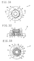
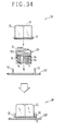
- a seventh embodiment of the present invention is shown in Figs. 31 to 34. It is distinguished from the first embodiment by the fact that the fitting piece 18 is replaced with another similar fitting piece 18F.
- the fitting piece 18F includes an inner tubular member 29 which is made of synthetic resin.
- An outer tubular body 30 is formed in the shape of a hexagon and includes the bolt insertion hole 12.
- the outer tubular body covers an outer circumferential portion of the inner tubular member 29.
- Fitting pieces 32, 32 are fitted and fixed into a flange 31 provided adjacent the end portion of the outer tubular body 30.
- the outer wall of the inner tubular member 29 is formed in the shape of a hexagon and has three or more guideposts 14, 14, 14.
- a nut 7F according to the seventh embodiment will have similar advantages to that according to the fifth embodiment.
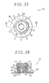
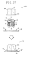
- FIG. 35 to 37 An eighth embodiment of the present invention is shown in Figs. 35 to 37. It is distinguished from the seventh embodiment by the fact that the outer tubular body 30 is replaced with another similar tubular body 30A.
- the outer tubular body 30A has a flange 31A in the shape of a disc which projects outwardly at end portion thereof.
- the flange 31A of the outer tubular body 30A is rotatably held by fitting pieces 32, 32 of the fitting plate 18F.
- a nut 7G according to the eighth embodiment will have similar advantages to that according to the seventh embodiment and the outer tubular body 30A allows rotation for screwing it onto the bolt.
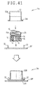
- a ninth embodiment of the present invention is shown in Figs 38 to 41. It is distinguished from the eighth embodiment by the fact that the outer tubular body 30A is replaced with another similar tubular body 30B that has an outer circumferential portion of the outer tubular body 30B formed in the shape of a disc.
- a nut 7H with the outer tubular body 30B according to the ninth embodiment will have similar advantages to that according to the eighth embodiment.
- a tenth embodiment of the present invention is shown in Figs. 42 to 44. It is distinguished from the seventh embodiment by the fact that the outer tubular body 30 is replaced with another similar tubular body 30C that has an outer circumferential portion of the outer tubular body 30C formed in the shape of a disc. A nut 71 with the outer tubular body 30C according to the tenth embodiment will have similar advantages to that according to the seventh embodiment.
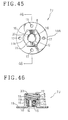
- FIG. 45 and 46 An eleventh embodiment of the present invention is shown in Figs. 45 and 46. It is distinguished from the first embodiment by the fact that the nut body 11A is formed integrally with a flange-shaped fitting plate 18A which is circular and comprises insertion holes 17, 17, 17 and 17. A washer 33 acts as a stopper, and supports a spring 19, which is fitted into the end portion of the bore having the largest diameter and fixed therein.
- the nut 7J according to the eleventh embodiment will have similar advantages to that according to the first embodiment.
- a twelfth embodiment of the present invention is shown in Figs. 47 to 49. It is distinguished from the eleventh embodiment by the fact that a fitting plate 18B is fitted rotatably into the nut body 11B.
- the nut 7K according to the twelfth embodiment may allow the nut body 11B to rotate, even when the fitting plate 18B is fixed to the beam or the like.
- the connector is described; however, the nuts 7, 7A, 7B, 7C, 7D, 7E, 7F, 7G, 7H, 7I, 7J and 7K may be used instead of the nut which screws onto the anchor bolt.
- the nuts 7, 7A, 7B, 7C, 7D, 7E, 7F, 7G, 7H, 7I, 7J and 7K may be used on anchor bolts laid underground or other bolts.
- the nut segments may be provided in a number greater than three. Additionally, the nut may be provided without three nut segments.
Landscapes
- Engineering & Computer Science (AREA)
- Architecture (AREA)
- General Engineering & Computer Science (AREA)
- Physics & Mathematics (AREA)
- Electromagnetism (AREA)
- Civil Engineering (AREA)
- Structural Engineering (AREA)
- Mechanical Engineering (AREA)
- Joining Of Building Structures In Genera (AREA)
- Springs (AREA)
- Transmission Devices (AREA)
- Braking Arrangements (AREA)
Applications Claiming Priority (4)
| Application Number | Priority Date | Filing Date | Title |
|---|---|---|---|
| JP11268598 | 1998-04-07 | ||
| JP11268598A JP4201219B2 (ja) | 1997-06-24 | 1998-04-07 | ナット |
| EP98309762A EP0949425B1 (de) | 1998-04-07 | 1998-11-27 | Mutter mit Federvorrichtung |
| CA002273042A CA2273042C (en) | 1998-04-07 | 1999-05-27 | Nut and connector |
Related Parent Applications (1)
| Application Number | Title | Priority Date | Filing Date |
|---|---|---|---|
| EP98309762A Division EP0949425B1 (de) | 1998-04-07 | 1998-11-27 | Mutter mit Federvorrichtung |
Publications (1)
| Publication Number | Publication Date |
|---|---|
| EP1158187A1 true EP1158187A1 (de) | 2001-11-28 |
Family
ID=32094410
Family Applications (2)
| Application Number | Title | Priority Date | Filing Date |
|---|---|---|---|
| EP98309762A Expired - Lifetime EP0949425B1 (de) | 1998-04-07 | 1998-11-27 | Mutter mit Federvorrichtung |
| EP01120005A Withdrawn EP1158187A1 (de) | 1998-04-07 | 1998-11-27 | Mutter mit Federvorrichtung |
Family Applications Before (1)
| Application Number | Title | Priority Date | Filing Date |
|---|---|---|---|
| EP98309762A Expired - Lifetime EP0949425B1 (de) | 1998-04-07 | 1998-11-27 | Mutter mit Federvorrichtung |
Country Status (5)
| Country | Link |
|---|---|
| US (1) | US6007284A (de) |
| EP (2) | EP0949425B1 (de) |
| AT (1) | ATE232267T1 (de) |
| CA (1) | CA2273042C (de) |
| DE (1) | DE69811204T2 (de) |
Families Citing this family (28)
| Publication number | Priority date | Publication date | Assignee | Title |
|---|---|---|---|---|
| JP2001097253A (ja) * | 1999-09-29 | 2001-04-10 | Nippon Pop Rivets & Fasteners Ltd | スペアタイヤの留め構造 |
| DE19958104C2 (de) * | 1999-12-02 | 2001-12-20 | Johann Sauer Eisenwarenfabrik | Vorrichtung zum Verbinden zweier Teile |
| JP4486240B2 (ja) * | 2000-09-25 | 2010-06-23 | 薫 種市 | ナット |
| JP4697694B2 (ja) * | 2000-11-02 | 2011-06-08 | 日本発條株式会社 | 簡易締結装置 |
| US20050062031A1 (en) * | 2003-09-22 | 2005-03-24 | Ted Mick | Method of securing railing structures for appearance and strength |
| ATE466201T1 (de) * | 2004-11-19 | 2010-05-15 | Ronald Smith | Gewindeklemmvorrichtung und verwendungsverfahren |
| US7752824B2 (en) * | 2005-03-14 | 2010-07-13 | Mitek Holdings, Inc. | Shrinkage-compensating continuity system |
| US7744322B2 (en) * | 2005-09-29 | 2010-06-29 | Kaoru Taneichi | Nut |
| US20080060296A1 (en) * | 2006-09-12 | 2008-03-13 | Espinosa Thomas M | Building having a hold down system |
| US20110220768A1 (en) * | 2010-03-11 | 2011-09-15 | Hayes John W | Portable mounting assembly |
| USD754775S1 (en) | 2011-03-10 | 2016-04-26 | John W. Hayes | Portable mounting assembly |
| CA3090083C (en) * | 2011-03-18 | 2023-09-19 | Thomas M. Espinosa | Concrete anchor coupling assembly and anchor rod holder |
| US8881478B2 (en) * | 2012-06-22 | 2014-11-11 | Simpson Strong-Tie Company, Inc. | Ratcheting take-up device |
| WO2014183125A1 (en) * | 2013-05-10 | 2014-11-13 | Qwikline Industrial Products, Inc. | Thread repair assembly and thread repair kit |
| DE102013213976A1 (de) * | 2013-07-17 | 2015-01-22 | Wobben Properties Gmbh | Verfahren zum Herstellen eines Fertigbetonteil-Segmentes eines Windenergieanlagen-Turmes |
| US9394706B2 (en) | 2013-10-08 | 2016-07-19 | Simpson Strong-Tie Company, Inc. | Concrete anchor |
| US9163655B2 (en) * | 2014-01-14 | 2015-10-20 | Kaoru Taneichi | Thrust nut |
| US9239073B2 (en) * | 2014-01-31 | 2016-01-19 | Kaoru Taneichi | Fastening device |
| CN107792270B (zh) * | 2017-10-10 | 2020-11-20 | 佛山市三轻自行车有限公司 | 一种自行车折叠器 |
| US10619344B1 (en) * | 2019-04-12 | 2020-04-14 | Kaoru Taneichi | Reinforcing hardware for wooden housing |
| CA3044632A1 (en) * | 2019-05-29 | 2020-11-29 | Gordian Enterprises Inc. | Split nut |
| EP3783233A1 (de) | 2019-08-21 | 2021-02-24 | Hilti Aktiengesellschaft | Gewindestangenverbinder mit zur öffnung hin fortsetzenden armen |
| EP3783235A1 (de) * | 2019-08-21 | 2021-02-24 | Hilti Aktiengesellschaft | Steckereinsatz mit stangenaufnahmebohrung |
| CN113374846B (zh) * | 2020-03-10 | 2022-09-13 | 银泰科技股份有限公司 | 回流弯管辅助器及应用其之滚珠螺杆 |
| JP7830453B2 (ja) * | 2020-10-21 | 2026-03-16 | ノルト‐ロック・スウィッツァランド・ゲー・エム・ベー・ハー | 締め付け構成要素において加えられる力の量を判定するための装置および方法 |
| CN113669352B (zh) * | 2021-08-26 | 2022-11-25 | 嘉兴涵祺汽配科技股份有限公司 | 一种具有保护功能的双头汽车螺栓 |
| US20230417042A1 (en) | 2022-06-24 | 2023-12-28 | PohlCon GmbH | Protecting connector |
| US12546129B2 (en) | 2023-02-22 | 2026-02-10 | Erico International Corporation | Connection system for concrete sections |
Citations (5)
| Publication number | Priority date | Publication date | Assignee | Title |
|---|---|---|---|---|
| US3151653A (en) * | 1959-06-17 | 1964-10-06 | Victor F Zahodfakin | Quick-locking fastening device |
| US4083393A (en) * | 1976-07-16 | 1978-04-11 | Mitsuchi Corporation | Nut |
| US4363164A (en) * | 1980-04-09 | 1982-12-14 | Mitsuchi Corporation | Device for removing dump nut from bolt |
| EP0352542A2 (de) * | 1988-07-25 | 1990-01-31 | The Vendo Company | Befestigungsvorrichtung |
| US5081811A (en) * | 1989-09-07 | 1992-01-21 | Housei Ttekou Co., Ltd. | Self-locking nut mechanism |
Family Cites Families (7)
| Publication number | Priority date | Publication date | Assignee | Title |
|---|---|---|---|---|
| US2814324A (en) * | 1953-06-05 | 1957-11-26 | Waldes Kohinoor Inc | Quick-acting nut having thread segments lever actuated by entrance of bolt |
| US3151652A (en) * | 1958-02-26 | 1964-10-06 | Victor F Zahodiakin | Fastening devices |
| US3075622A (en) * | 1960-11-08 | 1963-01-29 | Warren R Attwood | Structural connector |
| US3157215A (en) * | 1961-01-10 | 1964-11-17 | Victor F Zahodiakin | Quick-locking fastener with prevailing torque |
| US4197783A (en) * | 1978-05-03 | 1980-04-15 | Brown Company | Aligner tie |
| US4378187A (en) * | 1979-09-24 | 1983-03-29 | Fullerton Robert L | Quick-acting nut assembly |
| US5468105A (en) * | 1993-06-11 | 1995-11-21 | Iwamoto; Minekazu | Ceiling insert |
-
1998
- 1998-10-06 US US09/167,135 patent/US6007284A/en not_active Expired - Lifetime
- 1998-11-27 EP EP98309762A patent/EP0949425B1/de not_active Expired - Lifetime
- 1998-11-27 DE DE69811204T patent/DE69811204T2/de not_active Expired - Lifetime
- 1998-11-27 AT AT98309762T patent/ATE232267T1/de not_active IP Right Cessation
- 1998-11-27 EP EP01120005A patent/EP1158187A1/de not_active Withdrawn
-
1999
- 1999-05-27 CA CA002273042A patent/CA2273042C/en not_active Expired - Lifetime
Patent Citations (5)
| Publication number | Priority date | Publication date | Assignee | Title |
|---|---|---|---|---|
| US3151653A (en) * | 1959-06-17 | 1964-10-06 | Victor F Zahodfakin | Quick-locking fastening device |
| US4083393A (en) * | 1976-07-16 | 1978-04-11 | Mitsuchi Corporation | Nut |
| US4363164A (en) * | 1980-04-09 | 1982-12-14 | Mitsuchi Corporation | Device for removing dump nut from bolt |
| EP0352542A2 (de) * | 1988-07-25 | 1990-01-31 | The Vendo Company | Befestigungsvorrichtung |
| US5081811A (en) * | 1989-09-07 | 1992-01-21 | Housei Ttekou Co., Ltd. | Self-locking nut mechanism |
Also Published As
| Publication number | Publication date |
|---|---|
| ATE232267T1 (de) | 2003-02-15 |
| US6007284A (en) | 1999-12-28 |
| EP0949425B1 (de) | 2003-02-05 |
| CA2273042A1 (en) | 2000-11-27 |
| CA2273042C (en) | 2006-02-14 |
| DE69811204D1 (de) | 2003-03-13 |
| DE69811204T2 (de) | 2003-11-13 |
| EP0949425A1 (de) | 1999-10-13 |
Similar Documents
| Publication | Publication Date | Title |
|---|---|---|
| EP0949425B1 (de) | Mutter mit Federvorrichtung | |
| JP6511513B2 (ja) | 接続ナットおよびホールダウン工法 | |
| US8033530B2 (en) | Stair rail assembly | |
| KR100348420B1 (ko) | 로킹와셔및이를이용한로킹장치 | |
| US5170996A (en) | Handrail assembly | |
| US9631660B2 (en) | Self-drilling bolt and nut assembly | |
| US6523808B1 (en) | Mounting fixture for hollow fence posts | |
| US5122022A (en) | Fastening element for securing insulating strips and/or insulating boards to a solid base structure | |
| US20040156695A1 (en) | Nut with fitting piece projecting outwardly from an attachment part | |
| JP4201219B2 (ja) | ナット | |
| US5337440A (en) | Tool head brace | |
| US20090226281A1 (en) | Nut | |
| KR100988489B1 (ko) | 풀림방지용 너트캡 | |
| JPH08214993A (ja) | 露出しない固定装置 | |
| JP2022129431A (ja) | ラグスクリューボルトの取付け治具及び取付け方法 | |
| JP7728026B2 (ja) | アンカー | |
| KR200439245Y1 (ko) | 콘크리트 거푸집용 고정구 | |
| KR101304511B1 (ko) | 스페이서가 마련된 스트롱 앵커 볼트 | |
| KR20210155585A (ko) | 개구부 및 나사부마커가 구비된 볼트 | |
| US20260036152A1 (en) | Panel connector with additional interlock | |
| JP2002323027A (ja) | 木材用スクリューボルト及び締付け金具並びに木材用スクリューボルトを用いた固定装置 | |
| KR19980060488U (ko) | 가구결속용 고정구 | |
| JP7713348B2 (ja) | 水道用サドル付分水栓の出荷方法及び水道用サドル付分水栓 | |
| KR200271373Y1 (ko) | 앵커볼트 | |
| JPH0423141Y2 (de) |
Legal Events
| Date | Code | Title | Description |
|---|---|---|---|
| PUAI | Public reference made under article 153(3) epc to a published international application that has entered the european phase |
Free format text: ORIGINAL CODE: 0009012 |
|
| 17P | Request for examination filed |
Effective date: 20010829 |
|
| AC | Divisional application: reference to earlier application |
Ref document number: 949425 Country of ref document: EP |
|
| AK | Designated contracting states |
Kind code of ref document: A1 Designated state(s): AT BE CH CY DE DK ES FI FR GB GR IE IT LI LU MC NL PT SE |
|
| AX | Request for extension of the european patent |
Free format text: AL;LT;LV;MK;RO;SI |
|
| AKX | Designation fees paid |
Free format text: AT BE CH CY DE DK ES FI FR GB GR IE IT LI LU MC NL PT SE |
|
| 17Q | First examination report despatched |
Effective date: 20030616 |
|
| STAA | Information on the status of an ep patent application or granted ep patent |
Free format text: STATUS: THE APPLICATION IS DEEMED TO BE WITHDRAWN |
|
| 18D | Application deemed to be withdrawn |
Effective date: 20031028 |