EP1158202B1 - Canal de passage variable, accordable indépendamment - Google Patents
Canal de passage variable, accordable indépendamment Download PDFInfo
- Publication number
- EP1158202B1 EP1158202B1 EP01111619A EP01111619A EP1158202B1 EP 1158202 B1 EP1158202 B1 EP 1158202B1 EP 01111619 A EP01111619 A EP 01111619A EP 01111619 A EP01111619 A EP 01111619A EP 1158202 B1 EP1158202 B1 EP 1158202B1
- Authority
- EP
- European Patent Office
- Prior art keywords
- bleed
- piston
- valve assembly
- working chamber
- bleed valve
- Prior art date
- Legal status (The legal status is an assumption and is not a legal conclusion. Google has not performed a legal analysis and makes no representation as to the accuracy of the status listed.)
- Expired - Lifetime
Links
- 239000012530 fluid Substances 0.000 claims description 78
- 230000006835 compression Effects 0.000 claims description 42
- 238000007906 compression Methods 0.000 claims description 42
- 230000035939 shock Effects 0.000 description 46
- 239000006096 absorbing agent Substances 0.000 description 45
- 238000013016 damping Methods 0.000 description 22
- 230000007704 transition Effects 0.000 description 14
- 238000013461 design Methods 0.000 description 9
- 239000000725 suspension Substances 0.000 description 8
- 238000004891 communication Methods 0.000 description 5
- 238000007789 sealing Methods 0.000 description 4
- 238000011161 development Methods 0.000 description 3
- 230000001133 acceleration Effects 0.000 description 2
- 230000007423 decrease Effects 0.000 description 2
- 238000006073 displacement reaction Methods 0.000 description 2
- 230000009977 dual effect Effects 0.000 description 2
- 238000000034 method Methods 0.000 description 2
- 238000000926 separation method Methods 0.000 description 2
- 230000004913 activation Effects 0.000 description 1
- 230000004075 alteration Effects 0.000 description 1
- 230000000712 assembly Effects 0.000 description 1
- 238000000429 assembly Methods 0.000 description 1
- 230000001419 dependent effect Effects 0.000 description 1
- 238000010348 incorporation Methods 0.000 description 1
- 230000010354 integration Effects 0.000 description 1
- 230000001788 irregular Effects 0.000 description 1
- 238000012986 modification Methods 0.000 description 1
- 230000004048 modification Effects 0.000 description 1
Images


Classifications
-
- F—MECHANICAL ENGINEERING; LIGHTING; HEATING; WEAPONS; BLASTING
- F16—ENGINEERING ELEMENTS AND UNITS; GENERAL MEASURES FOR PRODUCING AND MAINTAINING EFFECTIVE FUNCTIONING OF MACHINES OR INSTALLATIONS; THERMAL INSULATION IN GENERAL
- F16F—SPRINGS; SHOCK-ABSORBERS; MEANS FOR DAMPING VIBRATION
- F16F9/00—Springs, vibration-dampers, shock-absorbers, or similarly-constructed movement-dampers using a fluid or the equivalent as damping medium
- F16F9/32—Details
- F16F9/34—Special valve constructions; Shape or construction of throttling passages
- F16F9/348—Throttling passages in the form of annular discs or other plate-like elements which may or may not have a spring action, operating in opposite directions or singly, e.g. annular discs positioned on top of the valve or piston body
Definitions
- the present invention relates generally to automotive dampers or shock absorbers which receive mechanical shock. More particularly, the present invention relates to a unique hydraulic valve assembly which allows greater tunability of the shock absorber, especially in the mode of low hydraulic fluid flow.
- shock absorbers are used in conjunction with automotive suspension systems to absorb unwanted vibrations which occur during driving. To absorb these unwanted vibrations, shock absorbers are generally connected between the sprung portion (body) and the unsprung portion (wheels) of the automobile. A piston is located within a working chamber defined by a pressure tube of the shock absorber, with the piston being connected to the sprung portion of the automobile through a piston rod. The pressure tube is connected to the unsprung portion of the automobile by one of the methods known in the art.
- the shock absorber is able, through valving, to limit the flow of damping fluid between opposite sides of the piston, when the shock absorber is compressed or extended, the shock absorber is able to produce a damping force which damps the unwanted vibration which would otherwise be transmitted from the unsprung portion to the sprung portion of the automobile.
- a fluid reservoir is defined between the pressure tube and the reserve tube.
- the fluid reservoir is in direct communication with the lower portion of the working chamber defined by the pressure tube (the area below the piston). All damping forces produced by the shock absorber are the result of piston valving when a full displacement valving system is used.
- a shock absorber In selecting the amount of damping that a shock absorber is to provide, at least three vehicle performance characteristics are considered. These three characteristics are ride comfort, vehicle handling and road holding ability. Ride comfort is often a function of the spring constant for the main springs of the vehicle as well as the spring constant for the seat and tires and the damping coefficient of the shock absorber. For optimum ride comfort, a relatively low damping force or a soft ride is preferred.
- Vehicle handling is related to the variation in the vehicle's attitude (i.e., roll, pitch and yaw). For optimum vehicle handling, relatively large damping forces, or a firm ride, are required to avoid excessively rapid variations in the vehicle's attitude during cornering, acceleration and deceleration.
- road holding ability is generally a function of the amount of contact between the tires and the ground. To optimize road handling ability, large damping forces, or a firm ride, are required when driving on irregular surfaces to prevent loss of contact between the wheel and the ground for excessive periods of time.
- shock absorbers have been developed to generate the desired damping forces in relation to the various vehicle performance characteristics. Shock absorbers have been developed to provide different damping characteristics depending on the speed or acceleration of the piston within the pressure tube. Because of the exponential relation between pressure drop and flow rate, it is a difficult task to obtain a damping force at relatively low piston velocities, particularly at velocities near zero.
- Low speed damping force is important to vehicle handling since most vehicle handling events are controlled by low speed vehicle body velocities.
- the low speed fluid circuit of the valving system will operate over a very small range of velocity. Therefore, the secondary or high-speed stage valving is activated at a lower velocity than is desired. Activation of the secondary valving at relatively low velocities creates harshness because of the shape of the fixed orifice bleed circuit force velocity characteristic is totally different in configuration than the shape of the high-speed circuit.
- variable orifice bleed disc Since the flow area is increased by the deflection of the variable orifice bleed disc, a small deflection in a large diameter variable orifice bleed disc provides a rapid increase in the flow area of the bleed orifice. This rapid increase in the flow area complicates the tuning between the low speed valving circuit and the secondary or high-speed valving circuit.
- variable orifice bleed valving circuits which are integrated with the mid/high speed valving systems.
- the integration of the low speed circuit with the mid/high speed circuit creates a system where the tuning of the low speed circuit affects the mid/high speed circuit and the tuning of the mid/high speed circuit affects the low speed circuit.
- shock absorbers includes the development of a valving system which can provide a smooth transition between a low speed valving circuit and the secondary valving or high speed valving circuit.
- the smooth transition between these two circuits helps to reduce and/or eliminate any harshness during the transition.
- the development of these systems has also been directed towards the separation of these two circuits in order to be able to independently tune each of these circuits.
- a damper with a piston assembly dividing an upper working chamber from a lower working chamber.
- the piston assembly comprises a compression valve assembly for controlling fluid during a compression stroke and a rebound valve assembly for controlling fluid flow during a rebound stroke.
- Each of the compression valve assembly and the rebound valve assembly comprises a high damping valve for a main flow passage and a low damping valve for a sub flow passage.
- a control valve element which is displaceable at three damping force characteristic positions. Depending on the position of the control valve element, the main flow passage can be fluid communicated with the sub flow passage. Hence, when the piston moves relatively slow, the damping fluid flows through the sub flow passage. As the piston speed becomes high, the damping fluid flows through the main flow passage.
- the present invention provides the art with a method for independently tuning damping forces at low piston velocities in order to improve the handling characteristics of the vehicle without creating harshness and is defined by a damper according to claim 1.
- the present invention provides a low speed variable orifice bleed circuit which is separate from the mid/high speed circuit or the secondary valving system.
- the secondary valving system of the present invention includes a first plurality of discs secured to the piston to close the midlhigh speed extension and compression fluid passages extending through the piston. The first plurality of discs deflect due to a pressure differential to open the mid/high speed extension or compression fluid passages during the second stage valving.
- the low speed variable orifice bleed circuit of the present invention includes a second plurality of discs secured to the piston but separate from the first plurality of discs.
- the second plurality of discs close the low speed extension and compression fluid passages extending through the piston.
- the second plurality of discs also deflect due to a pressure differential to open the low speed extension or compression fluid passages during the initial stage valving.
- the separation of these two valving systems allows the designer to separately optimize the tuning of each valving system to optimize the damping forces created by the shock absorber during both an extension stroke and a compression stroke of the shock absorber and thus improve the vehicle handling without creating harshness.
- the first metering device is prefereably a metering disc for limiting fluid flow through said first bleed valve assembly. It is advantageous if the metering disc defines a notch, said notch being sized to limit fluid flow through said first bleed valve assembly.
- Vehicle 10 includes a rear suspension 12, a front suspension 14 and a body 16.
- Rear suspension 12 has a transversely extending rear axle assembly (not shown) adapted to operatively support the vehicle's rear wheels 18.
- the rear axle assembly is operatively connected to body 16 by means of a pair of shock absorbers 20 and a pair of helical coil springs 22.
- front suspension 14 includes a transversely extending front axle assembly (not shown) to operatively support the vehicle's front wheels 24.
- the front axle assembly is operatively connected to body 16 by means of a second pair of shock absorbers 26 and by a pair of helical coil springs 28.
- Shock absorbers 20 and 26 serve to dampen the relative motion of the unsprung portion (i.e., front and rear suspensions 12 and 14, respectively) and the sprung portion (i.e., body 16) of vehicle 10. While vehicle 10 has been depicted as a passenger car having front and rear axle assemblies, shock absorbers 20 and 26 may be used with other types of vehicles or in other types of applications including, but not limited to, vehicles incorporating independent front and/or independent rear suspension systems. Further, the term "shock absorber" as used herein is meant to refer to dampers in general and thus will include McPherson struts.
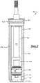
- shock absorber 26 is shown in greater detail. While Figure 2 shows only shock absorber 26, it is to be understood that shock absorber 20 also includes the variable bleed orifice valving in accordance with the present invention which is described below for shock absorber 26. Shock absorber 20 differs from shock absorber 26 in the away in which it is adapted to be connected to the sprung and unsprung portions of vehicle 10. Shock absorber 26 comprises a pressure tube 30, a piston assembly 32, a piston rod 34, a reservoir tube 36 and a base fitting 40.
- Pressure tube 30 defines a working chamber 42.
- Piston assembly 32 is slidably disposed within pressure tube 30 and divides working chamber 42 into an upper working chamber 44 and a lower working chamber 46.
- a seal 48 is disposed between piston assembly 32 and pressure tube 30 to permit sliding movement of piston assembly 32 with respect to pressure tube 30 without generating undue frictional forces as well as sealing upper working chamber 44 from lower working chamber 46.
- Piston rod 34 is attached to piston assembly 32 and extends through upper working chamber 44 and through an upper end cap 50 which closes the upper end of both pressure tube 30 and reservoir tube 36.
- a sealing system 52 seals the interface between upper end cap 50, pressure tube 30, reservoir tube 36 and piston rod 34.
- piston rod 34 opposite to piston assembly 32 is adapted, in the preferred embodiment, to be secured to the sprung portion of vehicle 10.
- Valving in piston assembly 32 controls the movement of fluid between upper working chamber 44 and lower working chamber 46 during movement of piston assembly 32 within pressure tube 30. Because piston rod 34 extends only through upper working chamber 44 and not lower working chamber 46, movement of piston assembly 32 with respect to pressure tube 30 causes a difference in the amount of fluid displaced in upper working chamber 44 than the amount of fluid displaced in lower working chamber 46. This difference in the amount of fluid displaced is known as the "rod volume" and it flows through base fitting 40. While shock absorber 26 is being illustrated as a dual tube shock absorber having base fitting 40, it is within the scope of the present invention to utilize piston assembly 32 in a mono-tube designed shock absorber if desired.
- Reservoir tube 36 surrounds pressure tube 30 to define a reserve chamber 54 located between the tubes.
- the bottom end of reservoir tube 36 is closed by an end cap 56 which is adapted, in the preferred embodiment, to be connected to the unsprung portion of vehicle 10.
- the upper end of reservoir tube 36 is attached to upper end cap 50.
- Base fitting 40 is disposed between lower working chamber 46 and reserve chamber 54 to allow the flow of fluid between the two chambers.
- the present invention is directed to a unique full flow piston assembly 32 which includes variable bleed orifice valving for both rebound and compression strokes which is independent of the mid/high speed valving.
- Piston assembly 32 provides an independent tunable smooth transition between the low speed valving and the mid/high speed valving in both a compression movement and a rebound movement of shock absorber 26.
- the damping characteristics for both rebound (extension) and compression for shock absorber 26 are determined by piston assembly 32 thus eliminating the need for a base valve assembly.
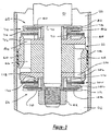
- piston assembly 32 comprises a piston 60, a compression valve assembly 62 and a rebound valve assembly 64.
- Piston 60 is secured to piston rod 34 and it defines a plurality of compression fluid passages 66 and a plurality of rebound fluid passages 68.
- Compression valve assembly 62 is disposed on the upper side of piston 60 adjacent a shoulder 70 defined by piston rod 34.
- Compression valve assembly 62 comprises a piston plate 72, a plurality of mid/high speed valve discs 74, a bleed valve body 76, a bleed valve disc 78, a bleed washer 80, and a bleed check plate 82.
- Piston plate 72 is disposed adjacent piston 60 and it defines a plurality of compression passages 84 that are in registry with the plurality of compression fluid passages 66 and 84.
- Bleed valve body 76 defines a plurality of compression bleed passages 86 which are also in fluid communication with the plurality of compression fluid passages 66.
- Valve discs 74 are sandwiched between a shoulder 88 on piston plate 72 and an annular surface 90 on bleed valve body 76 to close the plurality of compression passages 84 and thus the plurality of compression fluid passages 66.
- Bleed valve disc 78 is located adjacent bleed valve body 76 to close the plurality of bleed passages 86.
- Bleed washer 80 is disposed between bleed valve disc 78 and bleed check plate 82.
- Bleed check plate 82 is located adjacent shoulder 70 on piston rod 34.
- a retaining nut 92 is assembled to the end of piston rod 34. Nut 92 maintains the assembly of compression valve assembly 62, piston 60 and rebound valve assembly 64 as shown in Figure 3.
- the amount of deflection and thus the metering for the fluid flow is controlled by the thickness of bleed washer 80.
- the bleed flow of fluid will reach a saturation point due to bleed washer 80 and the pressure differential across mid/high speed valve discs 74 (which is the same pressure differential across disc 78) will increase and exert a sufficient load against valve discs 74 to cause deflection of valve discs 74 to allow additional flow of fluid between lower working chamber 46 and upper working chamber 44.
- the transition between the fluid flow past disc 78 and the fluid flow past discs 74 can be controlled by the design of bleed valve body 76, bleed valve disc 78, bleed washer 80 and bleed check plate 82.
- Factors that will affect the shape of the transition curve include, but are not limited to, the diameter of bleed valve body 76, the size of passages 86, the thickness, size and stiffness of bleed valve disc 78, the diameter and thickness of bleed washer 80 and the size of bleed check plate 82. All of the factors which control the shape of the transition curve are independent of the design for piston plate 72 and the plurality of mid/high speed valve discs 74. Thus, the tuning of the transition between low speed valving and mid/high speed valving is independent from the mid/high speed valving thus allowing the independent tuning of both valving systems.
- bleed valve body 76 interfaces between the low speed valving and the mid/high speed valving, the independence between these two valving systems is maintained since the low speed valving system is affected by the design of the upper surface of bleed valve body 76 while the mid/high speed valving system is affected by the design of the lower surface of bleed valve body 76.
- Rebound valve assembly 64 is disposed on the lower side of piston 60 adjacent retaining nut 92.
- Rebound valve assembly 64 comprises a second piston plate 102, a second plurality of midlhigh speed valve discs 104, a second bleed valve body 106, a second bleed valve disk 108, a second bleed washer 110, and a second bleed check plate 112.
- Piston plate 102 is disposed adjacent piston 60 and it defines a plurality of rebound passages 114 that are in registry with the plurality of rebound fluid passages 68.
- Bleed valve body 106 defines a plurality of rebound bleed passages 116 which are also in fluid communication with the plurality of rebound fluid passages 68 and 114.
- Valve discs 104 are sandwiched between a shoulder 118 on piston plate 102 and an annular surface 120 on bleed valve body 106 to close the plurality of rebound passages 114 and thus the plurality of rebound fluid passages 68.
- Bleed valve disc 108 is located adjacent bleed valve body 106 to close the plurality of bleed passages 116.
- Bleed washer 1 10 is disposed between bleed valve disc 108 and bleed check plate 112.
- Bleed check plate 112 is located adjacent retaining nut 92 which is assembled to the end of piston rod 34. Nut 92 maintains the assembly of compression valve assembly 62, piston 60 and rebound valve assembly 64 as shown in Figure 3.
- the amount of deflection and thus the metering for the fluid flow is controlled by the thickness of bleed washer 110.
- the bleed flow of fluid will reach a saturation point due to bleed washer 110 and the pressure differential across mid/high speed valve discs 104 (which is the same pressure differential across disc 108) will increase and exert a sufficient load against valve discs 104 to cause deflection of valve discs 104 to allow additional flow of fluid between upper working chamber 44 and lower working chamber 46.
- the transition between the fluid flow past disc 108 and the fluid flow past discs 104 can be controlled by the design of bleed valve body 106, bleed valve disc 108, bleed washer 110 and bleed check plate 112.
- Factors that will affect the shape of the transition curve include but are not limited to the diameter of bleed valve body 106, the size of passages 116, the thickness, size and stiffness of bleed valve disc 108, the diameter and thickness of bleed washer 110 and the size of bleed check plate 112. All of the factors which control the shape of the transition curve are independent of the design for piston plate 102 and the plurality of mid/high speed valve discs 104. Thus, the tuning of the transition between low speed valving and mid/high speed valving is independent from the mid/high speed valving thus allowing the independent tuning of both valving systems.
- bleed valve body 106 interfaces between the low speed valving and the mid/high speed valving, the independence between these two valving systems is maintained since the low speed valving system is affected by the design of the lower surface of bleed valve body 106 while the mid/high speed valving system is affected by the design of the upper surface of bleed valve body 106.
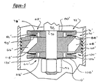
- Piston assembly 32' in accordance with another embodiment of the present invention is disclosed.
- Piston assembly 32' comprises a piston 60', a compression valve assembly 62' and a rebound valve assembly 64'.
- Piston 60' is secured to piston rod 34 and it defines a plurality of compression fluid passages 66' and a plurality of rebound fluid passages 68'.
- Compression valve assembly 62' is disposed on the upper side of piston 60' adjacent shoulder 70 defined by piston rod 34.
- Compression valve assembly 62' comprises a plurality of mid/high speed valve discs 74', a bleed valve body 76', a bleed valve disc 78' and a bleed washer 80'.
- Valve discs 74' are sandwiched between a shoulder 88' on piston 60' and an annular surface 90' on bleed valve body 76' to close the plurality of compression fluid passages 66'.
- Bleed valve body 76' defines a plurality of compression bleed passages 86' which are in communication with the plurality of compression fluid passages 66'.
- Bleed valve disc 78' is located adjacent bleed valve body 76' and adjacent bleed washer 80' to close the plurality of bleed passages 86' and 66'.
- Retaining nut 92 maintains the assembly of compression valve assembly 62', piston 60' and rebound valve assembly 64' as shown in Figure 5.
- compression valve assembly 62' During a compression stroke for shock absorber 20, the operation and function for compression valve assembly 62' is the same as that described above for compression valve assembly 62.
- Rebound valve assembly 64' is disposed on the lower side of piston 60' adjacent retaining nut 92.
- Rebound valve assembly 64' comprises a plurality of mid/high speed valve discs 104', a bleed valve body 106', a bleed valve disc 108' and a bleed washer 110'.
- Valve discs 104' are sandwiched between a shoulder 118' on piston 60' and an annular surface 120' on bleed valve body 106' to close the plurality of rebound fluid passages 68'.
- Bleed valve body 106' defines a plurality of rebound bleed passages 116' which are in communication with the plurality of rebound fluid passages 68'.
- Bleed valve disc 108' is located adjacent bleed valve body 106' and adjacent bleed washer 110' to close the plurality of bleed passages 116' and 68'.
- Retaining nut 92 maintains the assembly of compression valve assembly 62', piston 60' and rebound valve assembly 64' as shown in Figure 5.
- rebound valve assembly 64' During a rebound stroke for shock absorber 20, the operation and function for rebound valve assembly 64' is the same as that described above for rebound valve assembly 64.
Landscapes
- Engineering & Computer Science (AREA)
- General Engineering & Computer Science (AREA)
- Mechanical Engineering (AREA)
- Fluid-Damping Devices (AREA)
Claims (8)
- Amortisseur (26), comprenant :un tube de pression (30) formant une chambre de travail (42) ;un ensemble de piston (32, 32') disposé à l'intérieur de ladite chambre de travail (42), ledit ensemble de piston (32, 32') divisant ladite chambre de travail (42) en une chambre de travail supérieure (44) et une chambre de travail inférieure (46), ledit ensemble de piston (32, 32') comprenant :- un piston (60, 60') définissant un passage de fluide de compression (66, 66') s'étendant entre lesdites chambres de travail supérieure et inférieure (44, 46) et un passage de fluide de retour (68, 68') s'étendant entre lesdites chambres de travail supérieure et inférieure (44, 46) ;- un ensemble de soupape de compression (62, 62') attaché audit piston (60, 60') pour commander un écoulement de fluide à travers ledit passage de fluide de compression (66, 66') ;- un ensemble de soupape de retour (64, 64') attaché audit piston (60, 60') pour commander un écoulement de fluide à travers ledit passage de fluide de retour (68, 68') ;- un premier ensemble de soupape de purge attaché audit piston (60, 60') pour commander un écoulement de fluide entre ladite chambre de travail supérieure (44) et ladite chambre de travail inférieure (46), ledit premier ensemble de soupape de purge étant indépendant dudit ensemble de soupape de compression (62, 62') et dudit ensemble de soupape de retour (64, 64'), ledit premier ensemble de soupape de purge comprenant un premier dispositif de dosage pour limiter un écoulement de fluide à travers ledit premier ensemble de soupape de purge pour accorder ledit amortisseur ; et- un deuxième ensemble de soupape de purge attaché audit piston (60, 60') pour commander un écoulement de fluide entre ladite chambre de travail supérieure (44) et ladite chambre de travail inférieure (46), ledit deuxième ensemble de soupape de purge étant indépendant dudit ensemble de soupape de compression et dudit ensemble de soupape de retour, ledit deuxième ensemble de soupape de purge comprenant un deuxième dispositif de dosage pour limiter l'écoulement de fluide à travers ledit deuxième ensemble de soupape de purge pour accorder ledit amortisseur (26),
caractérisé en ce que ledit premier ensemble de soupape de purge est conçu de manière à permettre un écoulement de fluide entre la chambre de travail inférieure (46) et la chambre de travail supérieure (44) pendant la totalité des déplacements à basse vitesse dudit piston (60, 60'), et en ce que ledit deuxième ensemble de soupape de purge est conçu de manière à permettre un écoulement de fluide entre la chambre de travail supérieure (44) et la chambre de travail inférieure (46) pendant la totalité des déplacements à basse vitesse dudit piston (60, 60'). - Amortisseur selon la revendication 1, dans lequel ledit premier dispositif de dosage est une rondelle de passage (80, 80').
- Amortisseur selon la revendication 2, dans lequel ledit premier ensemble de soupape de purge comprend un disque de soupape de purge (78, 78'), la déflexion dudit disque de soupape de purge (78, 78') étant commandée par ladite rondelle de passage (80, 80').
- Amortisseur selon la revendication 1, dans lequel ledit premier dispositif de dosage est un disque de dosage destiné à limiter un écoulement de fluide à travers ledit premier ensemble de soupape de purge.
- Amortisseur selon la revendication 4, dans lequel ledit disque de dosage définit une encoche, ladite encoche étant dimensionnée de manière à limiter un écoulement de fluide à travers ledit premier ensemble de soupape de purge.
- Amortisseur selon l'une quelconque des revendications 1 à 5, dans lequel ledit deuxième dispositif de dosage est une deuxième rondelle de passage (110, 110').
- Amortisseur selon la revendication 6, dans lequel ledit deuxième ensemble de soupape de purge comprend un deuxième disque de soupape de purge (108, 108'), la déflexion dudit deuxième disque de soupape de purge (108, 108') étant commandée par ladite deuxième rondelle de passage (110, 110').
- Amortisseur selon l'une quelconque des revendications 1 à 7, comprenant en outre un tube de réservoir (36) disposé autour dudit tube de pression (30), ledit tube de réservoir (36) formant une chambre de réserve (54) entre ledit tube de pression (30) et ledit tube de réservoir (36).
Applications Claiming Priority (2)
| Application Number | Priority Date | Filing Date | Title |
|---|---|---|---|
| US09/575,900 US6460664B1 (en) | 2000-05-22 | 2000-05-22 | Independently tunable variable bleed orifice |
| US575900 | 2000-05-22 |
Publications (4)
| Publication Number | Publication Date |
|---|---|
| EP1158202A2 EP1158202A2 (fr) | 2001-11-28 |
| EP1158202A3 EP1158202A3 (fr) | 2003-02-12 |
| EP1158202B1 true EP1158202B1 (fr) | 2006-01-25 |
| EP1158202B2 EP1158202B2 (fr) | 2008-11-05 |
Family
ID=24302142
Family Applications (1)
| Application Number | Title | Priority Date | Filing Date |
|---|---|---|---|
| EP01111619A Expired - Lifetime EP1158202B2 (fr) | 2000-05-22 | 2001-05-12 | Canal de passage variable, accordable indépendamment |
Country Status (4)
| Country | Link |
|---|---|
| US (1) | US6460664B1 (fr) |
| EP (1) | EP1158202B2 (fr) |
| BR (1) | BR0102063B1 (fr) |
| DE (1) | DE60116813T3 (fr) |
Families Citing this family (52)
| Publication number | Priority date | Publication date | Assignee | Title |
|---|---|---|---|---|
| JP2004150574A (ja) * | 2002-10-31 | 2004-05-27 | Kayaba Ind Co Ltd | 油圧緩衝器の減衰力発生バルブ |
| US7070029B2 (en) * | 2003-09-15 | 2006-07-04 | Tenneco Automotive Operating Company Inc. | Monotube piston valving system with selective bleed |
| FR2883612B1 (fr) * | 2005-03-22 | 2010-09-10 | Peugeot Citroen Automobiles Sa | Dispositif d'amortissement a flux croises a deux couvercles sans indexage |
| FR2883611B1 (fr) * | 2005-03-22 | 2010-09-10 | Peugeot Citroen Automobiles Sa | Dispositif d'amortissement a flux croises a deux couvercles avec indexage |
| US7621382B2 (en) * | 2006-06-28 | 2009-11-24 | Nissan Technical Center North America, Inc. | Shock absorber |
| JP2008241017A (ja) * | 2007-03-29 | 2008-10-09 | Honda Motor Co Ltd | 油圧式緩衝装置 |
| US8083039B2 (en) * | 2007-08-29 | 2011-12-27 | Tenneco Automotive Operating Company, Inc. | Disc spring intake |
| US8997953B2 (en) * | 2007-08-30 | 2015-04-07 | Tenneco Automotive Operating Company Inc. | Shock absorber having a full displacement valve assembly |
| KR101227384B1 (ko) * | 2008-03-20 | 2013-01-30 | 주식회사 만도 | 쇽업소버의 밸브장치 |
| JP5290701B2 (ja) | 2008-03-26 | 2013-09-18 | 日立オートモティブシステムズ株式会社 | 流体圧緩衝器 |
| US8297418B2 (en) | 2008-06-05 | 2012-10-30 | Tenneco Automotive Operating Company Inc. | Nested check high speed valve |
| KR100909943B1 (ko) * | 2008-07-16 | 2009-07-29 | 주식회사 만도 | 변위 가변형 쇽업소버 |
| KR100918174B1 (ko) * | 2008-07-16 | 2009-09-17 | 주식회사 만도 | 변위 가변형 쇽업소버의 유동 피스톤 밸브 |
| US8439173B2 (en) * | 2008-09-25 | 2013-05-14 | GM Global Technology Operations LLC | Methods and apparatus for a suspension system with progressive resistance |
| KR20110001283A (ko) * | 2009-06-30 | 2011-01-06 | 주식회사 만도 | 쇽업소버의 피스톤 밸브 조립체 |
| US8616351B2 (en) | 2009-10-06 | 2013-12-31 | Tenneco Automotive Operating Company Inc. | Damper with digital valve |
| WO2012116190A1 (fr) * | 2011-02-24 | 2012-08-30 | Factory Kahne, Llc | Face de piston modulaire pour amortisseur |
| KR101288613B1 (ko) * | 2011-08-11 | 2013-07-22 | 주식회사 만도 | 쇽업소버의 피스톤 어셈블리 |
| KR101374875B1 (ko) * | 2011-12-30 | 2014-03-18 | 주식회사 만도 | 쇽업소버의 피스톤 어셈블리 |
| US10113604B2 (en) * | 2012-03-09 | 2018-10-30 | Fox Factory, Inc. | Suspension damper |
| JP5613191B2 (ja) * | 2012-03-28 | 2014-10-22 | カヤバ工業株式会社 | バルブ構造 |
| KR101374877B1 (ko) * | 2012-06-13 | 2014-03-18 | 주식회사 만도 | 쇽업소버의 피스톤 어셈블리 |
| JP5941359B2 (ja) * | 2012-07-10 | 2016-06-29 | Kyb株式会社 | 緩衝器のバルブ構造 |
| US9080629B2 (en) | 2012-09-07 | 2015-07-14 | Tenneco Automotive Operating Company Inc. | Multi-tuneable degressive valve |
| JP6014444B2 (ja) * | 2012-09-28 | 2016-10-25 | 日立オートモティブシステムズ株式会社 | 緩衝器 |
| NL2010038C2 (en) | 2012-12-21 | 2014-06-24 | Koni Bv | Shock absorber. |
| US9884533B2 (en) | 2013-02-28 | 2018-02-06 | Tenneco Automotive Operating Company Inc. | Autonomous control damper |
| KR20150121020A (ko) | 2013-02-28 | 2015-10-28 | 테네코 오토모티브 오퍼레이팅 컴파니 인코포레이티드 | 전자장치가 통합된 댐퍼 |
| US9217483B2 (en) | 2013-02-28 | 2015-12-22 | Tenneco Automotive Operating Company Inc. | Valve switching controls for adjustable damper |
| US9303715B2 (en) | 2013-03-10 | 2016-04-05 | Oshkosh Defense, Llc | Limiting system for a vehicle suspension component |
| US11199239B2 (en) | 2013-03-10 | 2021-12-14 | Oshkosh Defense, Llc | Suspension element systems and methods |
| US10632805B1 (en) * | 2017-04-27 | 2020-04-28 | Oshkosh Defense, Llc | Suspension element systems and methods |
| US12491943B1 (en) | 2013-03-10 | 2025-12-09 | Oshkosh Defense, Llc | Systems and methods for a military vehicle |
| US9879746B2 (en) | 2013-03-15 | 2018-01-30 | Tenneco Automotive Operating Company Inc. | Rod guide system and method with multiple solenoid valve cartridges and multiple pressure regulated valve assemblies |
| EP2971847A4 (fr) | 2013-03-15 | 2016-12-21 | Tenneco Automotive Operating Co Inc | Ensemble guide de tige comportant un ensemble soupape à éléments multiples |
| US9067471B2 (en) * | 2013-03-15 | 2015-06-30 | Tenneco Automotive Operating Company Inc. | Piston assembly with open bleed |
| US9163691B2 (en) | 2013-03-15 | 2015-10-20 | Tenneco Automotive Operating Company Inc. | Rod guide arrangement for electronically controlled valve applications |
| US9879748B2 (en) | 2013-03-15 | 2018-01-30 | Tenneco Automotive Operating Company Inc. | Two position valve with face seal and pressure relief port |
| CN105358863B (zh) * | 2013-07-12 | 2017-05-31 | 北京京西重工有限公司 | 液压减震器 |
| JP6114667B2 (ja) | 2013-09-17 | 2017-04-12 | Kyb株式会社 | 減衰弁 |
| JP6343685B2 (ja) | 2015-01-30 | 2018-06-13 | 日立オートモティブシステムズ株式会社 | 流体圧緩衝器 |
| US10233995B2 (en) * | 2016-03-17 | 2019-03-19 | Mando Corporation | Shock absorber for railway vehicle |
| US10588233B2 (en) | 2017-06-06 | 2020-03-10 | Tenneco Automotive Operating Company Inc. | Damper with printed circuit board carrier |
| US10479160B2 (en) | 2017-06-06 | 2019-11-19 | Tenneco Automotive Operating Company Inc. | Damper with printed circuit board carrier |
| US10746248B2 (en) | 2018-07-25 | 2020-08-18 | Tenneco Automotive Operating Company Inc. | Valve assembly |
| US11040754B2 (en) | 2019-01-18 | 2021-06-22 | Sram, Llc | Dampers for bicycle suspension components |
| CN112360913B (zh) | 2019-11-29 | 2022-04-19 | 北京京西重工有限公司 | 液压阻尼器和用于液压阻尼器组件的活塞 |
| EP4127506A1 (fr) * | 2020-03-27 | 2023-02-08 | DRiV Automotive Inc. | Ensemble amortisseur |
| US11441633B2 (en) * | 2020-08-14 | 2022-09-13 | DRiV Automotive Inc. | Damper assembly including intake valve in fluid chamber |
| US11009094B1 (en) * | 2021-01-08 | 2021-05-18 | Factory Kahne, Llc | System and method for using a piston face and shim in a shock absorber with varying port configurations |
| JP7470076B2 (ja) * | 2021-03-19 | 2024-04-17 | カヤバ株式会社 | バルブおよび緩衝器 |
| CN114738422B (zh) | 2022-03-18 | 2023-10-13 | 北京京西重工有限公司 | 阻尼器组件及用于阻尼器组件的活塞 |
Family Cites Families (29)
| Publication number | Priority date | Publication date | Assignee | Title |
|---|---|---|---|---|
| DE4110023A1 (de) | 1991-03-27 | 1992-10-01 | Ringsdorff Werke Gmbh | Stossdaempferkolben aus ungleichen, gefuegten teilen |
| NL251285A (fr) | 1959-05-06 | |||
| BE631369A (fr) | 1962-04-26 | 1900-01-01 | ||
| DE1505478A1 (de) | 1965-10-29 | 1969-09-25 | Bilstein August Fa | Stufenlos verstellbarer Stossdaempfer,insbesondere fuer Kraftfahrzeuge |
| US4610332A (en) | 1981-11-05 | 1986-09-09 | Ford Motor Company | Velocity sensitive valve element for a shock absorber |
| US4588053A (en) | 1984-09-19 | 1986-05-13 | The United States Of America As Represented By The Secretary Of The Air Force | Multiple rate shock isolator damping valve |
| DE3518327A1 (de) † | 1985-05-22 | 1986-11-27 | Boge Gmbh, 5208 Eitorf | Hydraulischer, verstellbarer schwingungsdaempfer |
| US4809828A (en) | 1987-07-01 | 1989-03-07 | Kabushiki Kaisha Showa Seisakusho | One-way damping valve mechanism for hydraulic damper |
| US5316113A (en) | 1987-11-19 | 1994-05-31 | Atsugi Motor Parts Company Ltd. | Hydraulic shock absorber |
| JPH01102536U (fr) | 1987-12-28 | 1989-07-11 | ||
| US4964493A (en) | 1988-04-06 | 1990-10-23 | Atsugi Motor Parts Company, Limited | Shock absorber with variable damping characteristics depending upon stroke speed |
| US4872537A (en) | 1988-06-06 | 1989-10-10 | Brian Warner | Adjustable damper means for shock absorber |
| DE3925470C2 (de) | 1988-08-02 | 1996-04-18 | Atsugi Motor Parts Co Ltd | Stoßdämpfer mit einer Dämpfungsventilkonstruktion mit einer innerhalb eines großen Bereichs variablen Dämpfungscharakteristik |
| JPH0251637A (ja) | 1988-08-12 | 1990-02-21 | Tokico Ltd | 減衰力調整式油圧緩衝器 |
| US5042624A (en) * | 1988-09-29 | 1991-08-27 | Atsugi Unisia Corporation | Hydraulic shock absorber with pre-loaded valve for linear variation characteristics of damping force |
| JPH0292154U (fr) | 1989-01-10 | 1990-07-23 | ||
| JP2964148B2 (ja) | 1989-04-20 | 1999-10-18 | トキコ株式会社 | 減衰力調整式油圧緩衝器 |
| JP2694465B2 (ja) * | 1989-05-19 | 1997-12-24 | トキコ株式会社 | 油圧緩衝器 |
| US4972929A (en) | 1989-06-07 | 1990-11-27 | Lord Corporation | Bidirectional dual disc valve assembly |
| US5332069A (en) | 1989-08-31 | 1994-07-26 | Kayaba Kogyo Kabushiki Kaisha | Shock absorber |
| JP2918293B2 (ja) | 1990-05-28 | 1999-07-12 | 株式会社ユニシアジェックス | 減衰力可変型緩衝器 |
| DE4025880A1 (de) † | 1990-08-16 | 1992-02-20 | Bilstein August Gmbh Co Kg | Steuerbarer hydraulischer schwingungsdaempfer |
| GB2250080B (en) | 1990-10-19 | 1994-08-17 | Tokico Ltd | Hydraulic shock absorber |
| FR2684957B1 (fr) | 1991-12-11 | 1994-03-04 | Eram | Dispositif d'ecretage pour amortisseur de train d'atterrissage d'aeronef, et amortisseur comportant un tel dispositif. |
| US5150775A (en) | 1991-12-19 | 1992-09-29 | General Motors Corporation | Steer-sensitive variable damper and method utilizing a ring valve |
| JP3383863B2 (ja) | 1993-03-08 | 2003-03-10 | トキコ株式会社 | 減衰力調整式油圧緩衝器 |
| JPH07233840A (ja) | 1994-02-22 | 1995-09-05 | Unisia Jecs Corp | 減衰力可変型ショックアブソーバ |
| US5425398A (en) | 1994-03-28 | 1995-06-20 | General Motors Corporation | Valve for automotive damper |
| JPH11153173A (ja) † | 1997-11-21 | 1999-06-08 | Kayaba Ind Co Ltd | 減衰バルブ構造 |
-
2000
- 2000-05-22 US US09/575,900 patent/US6460664B1/en not_active Expired - Lifetime
-
2001
- 2001-05-12 EP EP01111619A patent/EP1158202B2/fr not_active Expired - Lifetime
- 2001-05-12 DE DE60116813T patent/DE60116813T3/de not_active Expired - Lifetime
- 2001-05-22 BR BRPI0102063-3A patent/BR0102063B1/pt not_active IP Right Cessation
Also Published As
| Publication number | Publication date |
|---|---|
| DE60116813T2 (de) | 2006-11-02 |
| US6460664B1 (en) | 2002-10-08 |
| EP1158202B2 (fr) | 2008-11-05 |
| EP1158202A2 (fr) | 2001-11-28 |
| BR0102063B1 (pt) | 2009-01-13 |
| EP1158202A3 (fr) | 2003-02-12 |
| DE60116813T3 (de) | 2009-07-09 |
| BR0102063A (pt) | 2001-12-18 |
| DE60116813D1 (de) | 2006-04-13 |
Similar Documents
| Publication | Publication Date | Title |
|---|---|---|
| EP1158202B1 (fr) | Canal de passage variable, accordable indépendamment | |
| EP2158416B1 (fr) | Purge de jonction | |
| US6672436B1 (en) | Variable bleed orifice valving | |
| US5992585A (en) | Acceleration sensitive damping for automotive dampers | |
| US7216747B2 (en) | Amplitude controlled orifice valving | |
| US9067471B2 (en) | Piston assembly with open bleed | |
| EP1167810B1 (fr) | Amortisseur de chocs adaptable à basse vitesse, comprenant une plaque à orifices | |
| EP1312828B1 (fr) | Amortisseur sensible à l'accélération | |
| US6382372B1 (en) | Ported disc variable bleed orifice | |
| EP1312827B1 (fr) | Elément flottant de blocage d'un orifice dans un piston d'amortisseur | |
| EP0572040A1 (fr) | Procédé et dispositif pour absorber des chocs mécaniques | |
| US6148969A (en) | Frequency dependant damper | |
| EP1314908A2 (fr) | Amortisseur hydraulique comprenant une unité à clapet d'amortissement |
Legal Events
| Date | Code | Title | Description |
|---|---|---|---|
| PUAI | Public reference made under article 153(3) epc to a published international application that has entered the european phase |
Free format text: ORIGINAL CODE: 0009012 |
|
| AK | Designated contracting states |
Kind code of ref document: A2 Designated state(s): AT BE CH CY DE DK ES FI FR GB GR IE IT LI LU MC NL PT SE TR |
|
| AX | Request for extension of the european patent |
Free format text: AL;LT;LV;MK;RO;SI |
|
| PUAL | Search report despatched |
Free format text: ORIGINAL CODE: 0009013 |
|
| AK | Designated contracting states |
Designated state(s): AT BE CH CY DE DK ES FI FR GB GR IE IT LI LU MC NL PT SE TR |
|
| AX | Request for extension of the european patent |
Extension state: AL LT LV MK RO SI |
|
| 17P | Request for examination filed |
Effective date: 20030404 |
|
| AKX | Designation fees paid |
Designated state(s): DE FR GB |
|
| 17Q | First examination report despatched |
Effective date: 20041105 |
|
| GRAP | Despatch of communication of intention to grant a patent |
Free format text: ORIGINAL CODE: EPIDOSNIGR1 |
|
| GRAS | Grant fee paid |
Free format text: ORIGINAL CODE: EPIDOSNIGR3 |
|
| GRAA | (expected) grant |
Free format text: ORIGINAL CODE: 0009210 |
|
| AK | Designated contracting states |
Kind code of ref document: B1 Designated state(s): DE FR GB |
|
| REG | Reference to a national code |
Ref country code: GB Ref legal event code: FG4D |
|
| REF | Corresponds to: |
Ref document number: 60116813 Country of ref document: DE Date of ref document: 20060413 Kind code of ref document: P |
|
| ET | Fr: translation filed | ||
| PLBI | Opposition filed |
Free format text: ORIGINAL CODE: 0009260 |
|
| PLAX | Notice of opposition and request to file observation + time limit sent |
Free format text: ORIGINAL CODE: EPIDOSNOBS2 |
|
| 26 | Opposition filed |
Opponent name: THYSSENKRUPP BILSTEIN SUSPENSION GMBH Effective date: 20061025 |
|
| PLAF | Information modified related to communication of a notice of opposition and request to file observations + time limit |
Free format text: ORIGINAL CODE: EPIDOSCOBS2 |
|
| PLBB | Reply of patent proprietor to notice(s) of opposition received |
Free format text: ORIGINAL CODE: EPIDOSNOBS3 |
|
| PUAH | Patent maintained in amended form |
Free format text: ORIGINAL CODE: 0009272 |
|
| STAA | Information on the status of an ep patent application or granted ep patent |
Free format text: STATUS: PATENT MAINTAINED AS AMENDED |
|
| 27A | Patent maintained in amended form |
Effective date: 20081105 |
|
| AK | Designated contracting states |
Kind code of ref document: B2 Designated state(s): DE FR GB |
|
| PGFP | Annual fee paid to national office [announced via postgrant information from national office to epo] |
Ref country code: FR Payment date: 20100611 Year of fee payment: 10 |
|
| PGFP | Annual fee paid to national office [announced via postgrant information from national office to epo] |
Ref country code: GB Payment date: 20100519 Year of fee payment: 10 |
|
| GBPC | Gb: european patent ceased through non-payment of renewal fee |
Effective date: 20110512 |
|
| REG | Reference to a national code |
Ref country code: FR Ref legal event code: ST Effective date: 20120131 |
|
| PG25 | Lapsed in a contracting state [announced via postgrant information from national office to epo] |
Ref country code: FR Free format text: LAPSE BECAUSE OF NON-PAYMENT OF DUE FEES Effective date: 20110531 |
|
| PG25 | Lapsed in a contracting state [announced via postgrant information from national office to epo] |
Ref country code: GB Free format text: LAPSE BECAUSE OF NON-PAYMENT OF DUE FEES Effective date: 20110512 |
|
| PGFP | Annual fee paid to national office [announced via postgrant information from national office to epo] |
Ref country code: DE Payment date: 20160520 Year of fee payment: 16 |
|
| REG | Reference to a national code |
Ref country code: DE Ref legal event code: R119 Ref document number: 60116813 Country of ref document: DE |
|
| PG25 | Lapsed in a contracting state [announced via postgrant information from national office to epo] |
Ref country code: DE Free format text: LAPSE BECAUSE OF NON-PAYMENT OF DUE FEES Effective date: 20171201 |