EP1158718A2 - Virtuelle Nezte verwaltende Netzwerkverwaltung in einem Fahrzeug - Google Patents
Virtuelle Nezte verwaltende Netzwerkverwaltung in einem Fahrzeug Download PDFInfo
- Publication number
- EP1158718A2 EP1158718A2 EP01108323A EP01108323A EP1158718A2 EP 1158718 A2 EP1158718 A2 EP 1158718A2 EP 01108323 A EP01108323 A EP 01108323A EP 01108323 A EP01108323 A EP 01108323A EP 1158718 A2 EP1158718 A2 EP 1158718A2
- Authority
- EP
- European Patent Office
- Prior art keywords
- ecus
- network
- ecu
- message
- virtual network
- Prior art date
- Legal status (The legal status is an assumption and is not a legal conclusion. Google has not performed a legal analysis and makes no representation as to the accuracy of the status listed.)
- Granted
Links
- 238000000034 method Methods 0.000 claims description 53
- 238000004891 communication Methods 0.000 claims description 46
- 230000005540 biological transmission Effects 0.000 claims description 27
- 230000003213 activating effect Effects 0.000 claims description 8
- 230000004044 response Effects 0.000 claims description 7
- 230000002618 waking effect Effects 0.000 claims description 5
- 238000012544 monitoring process Methods 0.000 claims description 4
- 230000006870 function Effects 0.000 abstract description 21
- 230000004913 activation Effects 0.000 abstract description 19
- 238000013459 approach Methods 0.000 abstract description 6
- 230000000737 periodic effect Effects 0.000 abstract description 3
- 230000008569 process Effects 0.000 description 31
- 238000001994 activation Methods 0.000 description 20
- 238000012546 transfer Methods 0.000 description 7
- 230000009849 deactivation Effects 0.000 description 6
- 238000013461 design Methods 0.000 description 6
- 238000010438 heat treatment Methods 0.000 description 6
- 238000010586 diagram Methods 0.000 description 5
- 238000012545 processing Methods 0.000 description 5
- 238000011084 recovery Methods 0.000 description 5
- 230000008901 benefit Effects 0.000 description 4
- 230000001934 delay Effects 0.000 description 4
- 230000010354 integration Effects 0.000 description 4
- 230000003993 interaction Effects 0.000 description 4
- 230000008054 signal transmission Effects 0.000 description 4
- 238000001914 filtration Methods 0.000 description 3
- 230000009471 action Effects 0.000 description 2
- 230000008859 change Effects 0.000 description 2
- 238000006243 chemical reaction Methods 0.000 description 2
- 230000001419 dependent effect Effects 0.000 description 2
- 230000000994 depressogenic effect Effects 0.000 description 2
- 238000011161 development Methods 0.000 description 2
- 239000012634 fragment Substances 0.000 description 2
- 230000002401 inhibitory effect Effects 0.000 description 2
- 230000007246 mechanism Effects 0.000 description 2
- 238000012986 modification Methods 0.000 description 2
- 230000004048 modification Effects 0.000 description 2
- 230000004043 responsiveness Effects 0.000 description 2
- 238000010792 warming Methods 0.000 description 2
- 239000006227 byproduct Substances 0.000 description 1
- 238000010276 construction Methods 0.000 description 1
- 238000001514 detection method Methods 0.000 description 1
- 230000000694 effects Effects 0.000 description 1
- 239000003999 initiator Substances 0.000 description 1
- 238000005457 optimization Methods 0.000 description 1
- 230000003449 preventive effect Effects 0.000 description 1
- 230000009467 reduction Effects 0.000 description 1
- 230000002829 reductive effect Effects 0.000 description 1
- 230000002441 reversible effect Effects 0.000 description 1
- 238000000926 separation method Methods 0.000 description 1
- 230000001052 transient effect Effects 0.000 description 1
Images


Classifications
-
- H—ELECTRICITY
- H04—ELECTRIC COMMUNICATION TECHNIQUE
- H04L—TRANSMISSION OF DIGITAL INFORMATION, e.g. TELEGRAPHIC COMMUNICATION
- H04L12/00—Data switching networks
- H04L12/28—Data switching networks characterised by path configuration, e.g. LAN [Local Area Networks] or WAN [Wide Area Networks]
- H04L12/46—Interconnection of networks
- H04L12/4641—Virtual LANs, VLANs, e.g. virtual private networks [VPN]
-
- H—ELECTRICITY
- H04—ELECTRIC COMMUNICATION TECHNIQUE
- H04L—TRANSMISSION OF DIGITAL INFORMATION, e.g. TELEGRAPHIC COMMUNICATION
- H04L12/00—Data switching networks
- H04L12/28—Data switching networks characterised by path configuration, e.g. LAN [Local Area Networks] or WAN [Wide Area Networks]
- H04L12/40—Bus networks
- H04L12/40006—Architecture of a communication node
- H04L12/40039—Details regarding the setting of the power status of a node according to activity on the bus
-
- H—ELECTRICITY
- H04—ELECTRIC COMMUNICATION TECHNIQUE
- H04L—TRANSMISSION OF DIGITAL INFORMATION, e.g. TELEGRAPHIC COMMUNICATION
- H04L12/00—Data switching networks
- H04L12/28—Data switching networks characterised by path configuration, e.g. LAN [Local Area Networks] or WAN [Wide Area Networks]
- H04L12/40—Bus networks
- H04L12/403—Bus networks with centralised control, e.g. polling
- H04L12/4035—Bus networks with centralised control, e.g. polling in which slots of a TDMA packet structure are assigned based on a contention resolution carried out at a master unit
-
- H—ELECTRICITY
- H04—ELECTRIC COMMUNICATION TECHNIQUE
- H04L—TRANSMISSION OF DIGITAL INFORMATION, e.g. TELEGRAPHIC COMMUNICATION
- H04L12/00—Data switching networks
- H04L12/28—Data switching networks characterised by path configuration, e.g. LAN [Local Area Networks] or WAN [Wide Area Networks]
- H04L12/46—Interconnection of networks
- H04L12/4604—LAN interconnection over a backbone network, e.g. Internet, Frame Relay
- H04L12/462—LAN interconnection over a bridge based backbone
- H04L12/4625—Single bridge functionality, e.g. connection of two networks over a single bridge
-
- H—ELECTRICITY
- H04—ELECTRIC COMMUNICATION TECHNIQUE
- H04L—TRANSMISSION OF DIGITAL INFORMATION, e.g. TELEGRAPHIC COMMUNICATION
- H04L12/00—Data switching networks
- H04L12/28—Data switching networks characterised by path configuration, e.g. LAN [Local Area Networks] or WAN [Wide Area Networks]
- H04L12/40—Bus networks
- H04L2012/40267—Bus for use in transportation systems
- H04L2012/40273—Bus for use in transportation systems the transportation system being a vehicle
Definitions
- the present invention relates to networks used in vehicles to provide distributed control of various vehicle functions and, more particularly, to such networks which utilize different groupings of electronic control units (ECUs) to carry out different control tasks.
- ECUs electronice control units
- ECUs electronice control units
- vehicle functions can be operator-controlled or automated and are referred to herein generally as control tasks.
- control tasks can include, for example, controlling vehicle door locks, seat position, cruise control, entertainment system devices (tuners, CD players, etc.), HVAC, intrusion alarms, interior and exterior lighting, electric window position, engine and vehicle system diagnostics, and, more recently, tasks such as seat heating and reverse sensing.
- the ECUs are typically connected together via one or more vehicle buses, which are generally implemented as serial communication buses in the form of a local area network.
- vehicle buses which are generally implemented as serial communication buses in the form of a local area network.
- any reliable communication strategy must also ensure that a number of other ancillary tasks are performed.
- One of these tasks is called network management and is used to provide a system-wide common approach to handling such things as: orderly start up (activation) of communication capabilities; orderly shut down (deactivation) of communication capabilities; and predictable recovery from detectable communication errors.
- Mechanisms to perform orderly start up and shut down are important so that ECUs can synchronize their signal reception expectations with the other ECUs signal transmission availability. If this synchronization does not occur, an ECU may interpret the lack of signal transmissions as the failure of one of the other ECUs and adopt safe default signal values that may be perceived by the occupant as improper vehicle operation. For example, headlights may default "on” if the day/night sensor signal is not transmitted in a timely manner.
- the present invention provides an on-board vehicle network and method for operating the network which permits an ECU to activate the other ECUs used for a particular vehicle control task without having to know in advance what ECUs are utilized in performing the control task.
- the network comprises a plurality of on-board vehicle electronic control units (ECUs) connected together via at least one network bus, with the network being arranged into a plurality of virtual networks that each comprise a group of the ECUs that together perform a vehicle control task.
- ECUs that together comprise a first one of the virtual networks are operable together to perform a first control task and are each identified using a first code that is associated with the first virtual network.
- the ECUs that comprise the second virtual network are operable together to perform a second control task and are each identified using a second code that is associated with the second virtual network.
- the first and second virtual networks can be activated using respective first and second messages that they receive over the vehicle bus. Once activated a virtual network is then operable to perform its associated control task.
- the messages include one or more of the codes used to identify the ECUs in a particular virtual network. In this way, an ECU can wake-up other ECUs out of their standby mode without having to know which ECUs are a part of the virtual network used to implement a particular control task.
- a method of managing an on-board vehicle network that utilize ECUs that can be switched between and active state and a low power quiescent state.
- the network includes at least one group or subset of the ECUs on the network, with the group of ECUs being operable together to perform a particular vehicle control task.
- the method includes the steps of: receiving a signal request for activating a control task; waking up the ECUs out of the low power quiescent state; and sending a message to the ECUs that includes a code associated with the control task.
- This message is received by some or all of the ECUs in the network and, for each of these ECUs, if the code included with the message corresponds to a control task associated with the ECU, then the ECU enters into an active state in which the ECU is operable to perform the control task together with other ECUs associated with the control task. However, if the code included with the message does not correspond to a control task associated with the ECU, then it enters into the low power quiescent state.
- the messages to the ECUs can be preceded by a wake-up signal which switches all of the quiescent ECUs to the active state.
- the ECUs Once the ECUs are awakened, they each monitor the network for receipt of a message containing a code associated with one of the control tasks for which they are used. If no code is received within a period of time following the wake-up signal, they switch back to their low power quiescent state. If a code is received, then each ECU checks to see whether it is associated with the received code; if so, it enters into a program mode in which it operates with the other appropriate ECUs to carry out the associated control task. If not, the ECU switches back to the quiescent state.
- any ECU on the network can be used to activate other ECUs associated with a particular control task, and can do so without having to know which or how many other ECUs are involved.
- This permits system designs in which a particular ECU can be used on different vehicle platforms, even if the function is performed differently on each platform.
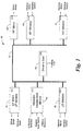
- the network 10 includes a number of electronic control units (ECUs) connected to each other by way of an in-vehicle network bus 12, which can be a serial communication bus or other suitable datalink.
- ECUs electronice control units
- the illustrated network 10 includes a total of seven ECUs which support the following control tasks:
- the network 10 includes the following ECUs.
- a driver's control panel (DCP) ECU 14 is used to manage the driver's switch bank that includes window, mirror and heated seat switches.
- a left front zone (LFZ) ECU 15 is used to manage the left front window and mirror motors. The remaining five modules are each dedicated to a single task.
- the left rear window (LRW) ECU 16, right rear window (RRW) ECU 17, and right front window (RFW) ECU 18 manage their corresponding window switches and motors.
- the driver's heated seat (DHS) ECU 19 manages the seat heating coil and the right front mirror (RFM) ECU 20 manages the corresponding mirror motor.
- the following table lists the different ECUs and their associated vehicle functions (control tasks). As noted above, some of the ECUs are used to carry out more than one control task, whereas others are dedicated to a single task. Thus, for example, the driver control panel (DCP) ECU is used in performing all three control tasks, whereas the driver's heated seat (DHS) ECU is dedicated to warming of the driver's seat and does not play a role in any other vehicle function.
- DCP driver control panel
- DHS driver's heated seat
- the illustrated ECUs 14-20 on network 10 are separated into three virtual networks - one for each of the three control tasks noted above.
- the seven ECUs can be separated into a power windows virtual network 22, a heated seat virtual network 23, and a power mirrors virtual network 24.
- the window virtual network 22 includes the driver control panel ECU 14 as well as the four ECUs 15-18 used to control the motors for the four windows.
- the heated driver's seat virtual network 23 includes the driver control panel ECU 15 and driver's heated seat ECU 19.
- the power mirrors virtual network 24 includes the left front zone ECU 14, the driver control panel ECU 15, and the right front mirror ECU 20.
- a primary advantage of the separation of the network into these virtual networks according to the various control tasks is that the ECUs on the vehicle bus 12 can be maintained in a low power quiescent state when not in use and then only those ECUs needed for a particular control task need be woken up and maintained in an activated state.
- moving the left mirror requires communication between the driver control panel and left front zone ECUs because the mirror control switch is connected to the driver control panel ECU 14 while the left mirror motor is controlled by the left front zone ECU 15.
- a switch activation from the driver to move the left mirror is detected by driver control panel ECU 14, which activates the power mirror virtual network 24.
- This activation includes waking up the ECUs from their standby state (assuming some or all of them are not already awake and performing some other function) and then executing the appropriate control logic to perform the function.
- This control logic can be programmed into the various ECUs so that they communicate together properly to implement the particular control task - in this case, movement of the left mirror.
- the control input for the driver's heated seat is to an ECU (the driver control panel ECU 14) that is different than the ECU used to activate the seat warmer (the driver's heated seat ECU 19).
- the heated seat virtual network 23 is activated whenever the appropriate switch on the driver's control panel is selected.
- the activation of a virtual network to perform a particular control task need not originate from one of the ECUs 14-20; rather, they can come from another source such as another ECU on the vehicle bus 12.
- an example of this is the use of yet another ECU (not shown) which is connected to receive inputs from the ignition system so that, upon detecting a personalized key unique to the driver, a signal is sent by this other ECU to ECUs 14, 15, and 20 to activate the mirror virtual network and move the mirrors to a preset position that has previously been stored in memory for this particular driver.
- the extra ECU would be included in the mirror virtual network 24.
- activation of this virtual network to move the side mirrors to a preset position could come from yet another ECU (not shown) that is part of a remote communication system that receives signals from a key fob or other remote transmitter.
- each of the three virtual networks is activated anytime one of its associated switch inputs is selected.
- the window virtual network 22 is activated via the ECU 18 which senses the keypress.
- the right front window ECU 18, although a part of the window virtual network 22 that includes five of the ECUs, may be implemented in a manner that does not require any network communication when the front right door window switch is activated, since both that switch and the associated right front window motor are controlled by the same ECU.
- the driver control panel (DCP) switch for the right front door window is depressed by the driver, different ECUs are used for detecting the switch event and activating the window motor. Accordingly, the window virtual network is activated, including both those ECUs used to accomplish the right front window control function and those ECUs in the virtual network (such as the left and right rear window ECUs) that are not involved in the particular window activation.
- DCP driver control panel
- a significant advantage of this use of virtual networks is that the network management strategy permits the activation of the necessary ECUs to perform a control task without the various ECUs involved having to know which or how many other ECUs are required for the particular task. This permits the many control tasks to be implemented using multiple ECUs in a modular, distributed manner while allowing a greater degree of independence of the control logic for a particular ECU between different vehicle platforms. This aspect of the invention is discussed next.
- the network management of the virtual networks 22-24 uses a messaging protocol over the vehicle bus 12 that permits all ECUs within a particular virtual network to be activated and maintained in an operational state until the associated control task is complete.
- the activation of the ECUs within a virtual network is typically initiated by one of the ECUs in the virtual network, although other triggers and sources can be used.
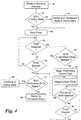
- a preferred method of activating one of the virtual networks is shown generally in Fig. 3 and the processing of wake-ups and messages relating to the virtual networks is shown in Fig. 4.
- activation of a virtual network involves waking up the ECUs on the vehicle bus in response to a control task request (such as a button activation by the driver), sending a message over the bus to activate the virtual network associated with that control task, and then sending periodic messages to keep the ECUs in the virtual network active until the control task is complete.
- a control task request such as a button activation by the driver
- the process begins upon receipt of a signal request to activate a control task.
- This signal request can originate from a switch activated by the driver or other vehicle occupant, or can be automatically generated either by a sensor or as the result of some vehicle software process.
- This request is received by one of the ECUs which responds at block 32 by sending a wake-up signal over the vehicle bus to the other ECUs.
- This wake-up signal can be a high-voltage wake-up as defined in SAE J2411 "Single Wire CAN Network for Vehicle Applications-Recommended Practice."
- the ECU that transmits the wake-up is considered the master ECU for this control event and is responsible for activating the virtual network associated with the requested control task.
- ECUs can simultaneously be the master for different, concurrent control tasks and a single ECU can be a master for more than one concurrent control task.
- the seat heater switch on the driver control panel is selected, the heated seat virtual network 23 is activated, with ECU 14 being the master.
- the window virtual network 22 is activated with ECU 18 being the master and the other ECUs on that virtual network being the slaves.
- ECU 14 would simultaneously be a master for purposes of the seat heating virtual network 23 and a slave for purposes of the window virtual network 22.
- VNM virtual network message
- the timer is used to send periodic follow-up VNMs that notify other ECUs in the virtual network that the control task is not yet complete and that they should therefore remain in the active state to carry out their portion, if any, of the control task logic.
- Fig. 3 The process of Fig. 3 is that carried out by a master ECU to control the activation of one of the virtual networks.
- Fig. 4 there is shown the process used by a slave ECU when a wake-up signal and VNM is received.
- Each of the ECUs is either operating in its quiescent state to conserve power or its active state in support of a control task.
- blocks 50, 52, and 54 upon receipt of a wake-up signal over the vehicle bus from a master ECU, each ECU on the vehicle bus is switched into its active state if not already operating in that state. Then, a count-down timer is started, as indicated at block 56.
- this timer is to provide an eight second period of time during which the ECU monitors the bus for a VNM indicating which virtual network should be initiated. Note that this period of time is selected to be longer than the three second repeat rate of the timer used in Fig. 3 so that this timer should not expire as long as follow-up VNMs are being sent.
- a VNM is received, then a check is made at block 68 to determine whether the virtual network identified in the message is one in which the ECU is a part. As will be discussed below in connection with Fig. 5, this identification can be accomplished using a code within the message that is unique to the virtual network. If the ECU is not part of the virtual network identified by the code, then the process moves back to block 60 to check the eight second timer and either continue monitoring for additional VNMs at block 58 or exit out of the loop by way of block 62, as appropriate. If the ECU is within the identified virtual network, then the process moves to block 70 where the ECU along with all others in that virtual network are switched into an operational mode in which they work together to perform the control task associated with the virtual network.
- a count-down timer is also begun at block 72. This timer can be the same as that used at block 60.
- a check is made to determine if a follow-up VNM has been received. If so, then the virtual network is to remain active and the process returns to block 72 to reset and restart the timer. If no VNM has been received, the timer is checked at block 76 to determine whether it has expired. If the timer has expired, then the virtual network is no longer active and the process moves to block 62 to determine the appropriate ECU state of operation. If the timer has not yet expired, the process returns to block 74 to continue monitoring for a proper VNM. It will of course be appreciated that this timer, as well as all others mentioned herein, can be implemented in software by the ECU itself.
- each ECU responds in exactly the same manner to wake-up requests and VNMs, regardless of whether it is a master ECU or slave ECU, or both.
- each master ECU responds as a slave to its own broadcasted VNM according to the process of Fig. 4, even though it was the initiator of that message.
- a single virtual network need not only have one master at a time. Rather, each triggering event (such as a switch activation by a passenger) can begin a virtual network and maintain it active until the function has been performed to completion.
- the window virtual network 22 is activated with ECU 17 being the master and therefore sending an initializing VNM as well as follow-up (continuing) VNMs.
- ECU 14 also sends an initializing VNM as well as follow-up VNMs.
- Each master continues sending these VNMs until its associated task is complete. In this way, each master ECU maintains the virtual network active as long as it is needed. Thus, from a network management viewpoint, the completion of one task has no effect on the performance of another, since each master ECU maintains the virtual network active independently of the other.
- VNM virtual network message
- These messages are transmitted as a frame 80 that includes a header 82, an initial byte 84 that identifies the message type, and seven network identifier bytes 86 that are used to identify the virtual network being activated by the message.
- Header 80 provides a frame ID that is separated into two parts: the first part is a fixed bit pattern ('11000' in the illustrated embodiment) that identifies the message as a VNM, and the second part is an ECU ID, which is unique to each ECU and is used to identify which ECU is transmitting the message.
- the fixed bit pattern comprises the five high-order bits (b6-b10) of the frame ID 82 and can be used to facilitate filtering of the messages by the ECUs.
- the ECU ID comprises the low-order six bits (b0-b5) of the frame ID and permits the unique identification of up to sixty-four different ECUs.
- the message type byte 84 comprises byte0 of the message data. It includes a low-order bit (b0) that is used as a flag to indicate whether the VNM is an initial VNM (that is used to initiate the virtual network) or a follow-up VNM (that is used maintain the virtual network active). The higher order bits of byte0 can be used for additional flags are data, as desired.
- the remaining seven bytes are virtual network ID bits which uniquely identify one or more virtual networks.
- Each virtual network ID is in the form of a code that is unique to that virtual network and that is therefore uniquely associated with the control task for which that virtual network exists. Since the seven bytes provide up to 56 bits, each bit position can correspond to a different one of the virtual networks, with a zero (cleared bit) indicating that the virtual network associated with that bit position is not being activated by the message and a one (set bit) indicating that it is.
- the code for a particular virtual network can comprise a single bit located in a selected position within the VNM.
- bit positions rather than sequential binary numbers to identify the different virtual networks allows an ECU that is currently the master of multiple virtual networks to send a single VNM that operates to maintain all of those virtual networks active.
- These assigned bit positions can also be used to simplify the processing required by each ECU to determine whether it is a part of the virtual network being activated.
- One or more of the bits in these seven bytes can be reserved for designating a common virtual network used on different vehicle platforms, such as a diagnostics virtual network.
- each message includes the information necessary to: differentiate it from other messages; identify the ECU from which the message originates; identify the type of message; and identify the virtual network(s) for which initial or continued activation is being requested.
- the following example depicts the complete process of activating one of the virtual networks of Fig. 2, maintaining it active until its associated control task is complete, and then deactivating the network.
- operation of the heated seat virtual network will be described as it would occur in response to activation of the heated seat switch by the driver on the driver control panel, with the starting assumption being that all of the ECUs are asleep when the driver switches on the seat heater.
- activation of the virtual network could also be the result of some automated system, rather than by the driver, such as by way of another ECU that switches on the seat heater automatically when the vehicle ignition is turned on during cold ambient temperatures.
- the ability to wake-up and maintain only a subset of the ECUs in an active state to carry out a control task is advantageous because it helps limit the amount of time the ECUs are operating in the higher current active state. This is especially true for ECUs such as the DHS ECU 19 which only needs to be activated on the infrequent occurrence of a request for warming the driver's seat.
- the network management approach used with these virtual networks allows ECUs to be developed for certain control tasks in a manner that can be independent of the vehicle platform. It also enables independent design of many of the ECUs since they do not have to know what other ECUs are included on the vehicle bus to carry out their assigned task; rather, they simply need to be programmed with their portion of the control logic for each task and must know what inputs to receive and what outputs to provide. This helps reduce ECU development time, since they can be developed more independently of each other.
- the network management approach discussed above also provides a more orderly start-up and shut-down of the ECUs than exists in many of the conventional network designs.
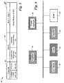
- a second physical network fragment for an entertainment subsystem for a vehicle The entertainment system is designed to support a tuner AM/FM reception, a cassette tape player, and a CD player, as represented by their respective ECUs 90, 92, and 94. Each of these ECUs are connected to the vehicle bus 12 along with an ECU 96 for an audio amplifier, and an ECU 98 for a power antenna.
- the vehicle bus 12 includes additional ECUs for other vehicle systems and functions, including, for example, a body control module (BCM) 100, as well as the ECUs of Figs. 1 and 2.
- BCM body control module
- the entertainment subsystem is separated into three virtual networks - one for radio, one for the tape player, and one for the CD player.
- the radio virtual network includes the tuner, amplifier, and antenna ECUs (i.e., ECUs 90, 96, and 98).
- the cassette virtual network includes the cassette ECU 92 and amplifier ECU 96.
- the CD player virtual network includes the CD player ECU 94 and the amplifier ECU 96.
- ECUs of the entertainment subsystem By organizing the ECUs of the entertainment subsystem into the virtual networks in this manner, the development, integration, and operation of the ECUs that are dedicated to one audio media can be decoupled from those dedicated to another of the audio media. For example, whereas a conventional network management technique for these entertainment ECUs would operate by starting up and shutting down all of the ECUs together, the use of virtual networks as shown in Fig. 6 permits the CD Player virtual network to activate ECUs 94 and 96 only. Thus, ECUs 90, 92, and 98 can all be allowed to sleep while the vehicle CD player is utilized, thereby reducing overall power consumption.
- any of the sources can be simply included or excluded without affecting the other ECUs in the entertainment subsystem.
- CD player virtual network support into the amplifier ECU 96
- a CD player and its ECU 94 can be added if desired to a particular vehicle without requiring a change in any of the other ECUs.
- other independent integrations are possible as well.
- the tuner ECU 90 could be integrated in with the amplifier ECU 96 into a single ECU that performs both functions and this integration can be accomplished without affecting the cassette or CD player ECUs 92, 94 or their associated virtual networks.
- control task encompasses different vehicle functions at many different levels of generality and specificity.
- a control task could be generally defined as controlling the vehicle audio entertainment system (using a single virtual network) or could be divided into more specific tasks, such as controlling the tuner, cassette player, or CD player (using three separate virtual networks).
- the discussion thus far has been directed to use of the invention in connection with a single physical bus.
- the invention can also be used in conjunction with multiple on-board vehicle buses.
- Operator-controlled functions of the type discussed above in connection with Figs. 1, 2, and 6 are typically implemented on a low-speed bus where system response time requirements are on the order of 100-200 msec.
- the vehicle might also include a high-speed bus for use in sharing real time data such as driver-commanded torque, actual engine torque, steering angle, and so forth.
- a mid-speed bus might also be included for advanced information and entertainment purposes, such as where large amounts of data must be transmitted in a relatively short time, as in, for example, advanced display or navigation systems.
- gateways are used to interface between these different buses so that the wake-up signals and virtual network messages (VNMs) can be transferred from one bus to another.
- VNMs virtual network messages
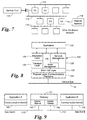
- three physical, on-board buses are shown: a high-speed bus 110, a low-speed bus 112 (such as vehicle bus 12 shown in Figs. 1, 2, and 6), and a third-party bus 114 such as might be used in an industry-developed entertainment system.
- a service tool 116 such as a diagnostic code scanner, and a remote network 118 which is accessed via satellite communications or otherwise.
- gateway G1 which interfaces between the high- and low-speed buses 110, 112
- gateway G2 which interfaces between the high-speed bus 110 and service tool 116
- gateway G3 which interfaces between the low-speed bus 112 and third party bus 114
- gateway G4 which interfaces between the low-speed bus 112 and the remote network 118.
- Fig. 8 depicts a conceptual layout of a communication kernel 120 that can be used by each of the ECUs in communicating with its respective bus.
- This communication kernel provides a standardized interface between the bus and the application process 122 being executed by the ECU. It includes both software and physical layers. More specifically, the communication kernel 120 includes a physical layer 124 that provides a conversion of the digital data symbols (1's and 0's) generated by the data link layer 126 into electrical signals transmitted on the bus.
- the physical layer 124 includes such things as bus transceivers, filtering, and the physical wiring to connect the ECU to the bus.
- the data link layer 126 provides services for the transfer of individual frames between nodes (ECUs). It handles the protocol of the bus system (e.g., bit timing, arbitration, and error detection).
- the kernel includes a network management layer 128 that is used to control the start-up, shutdown, and error handling for the ECUs where these functions involve interaction among the ECUs and therefore have to be managed globally, and also includes a node management layer 130 that is used to control the start-up, shutdown, and error handling where these functions do not involve interaction with the other ECUs and therefore can be managed locally.
- the kernel 120 further includes a transport layer 132 that transfers data packets using services of the data link layer 126. It provides an unacknowledged transport service (1:N communication, 1:1 communication). If long messages have to be transferred over the network, the transport layer provides services for segmented data transfer. On the transmit side, the message is broken into segments, each segment being short enough to fit in a single network frame.
- the transport layer 132 also provides connect setup and flow control.
- the kernel 120 also includes an interaction layer 134 that serves as the application program interface. It provides communication services to the application 122 independent of the bus protocol and uses services of the transport layer 132 for communicating on the bus.
- each gateway node is connected to at least 2 buses and will interact with each network according to its message strategy and transmission models.
- the gateway includes a separate communication kernel 140, 142 for each of the two networks. This gateway node normally carries out several application tasks where the gateway function is merely one of them.
- the gateway interacts with the bus kernels' interaction layers 134 and performs some or all of the following services: transfer of wake-up requests to other networks; transfer of virtual network information such as VNMs to other networks; transfer of signals between networks; support of signal parameter processing (event generation, data conversion, data filtering, etc.); and transfer of block information with USDT protocol.
- VNMs are transmitted every three seconds (when required) and initializing VNM transmissions can essentially be unrestricted.
- the transmission speed is high enough that processor demand associated with uncontrolled bursts of VNMs may be unacceptable.
- the ECUs can be programmed with a burst algorithm that periodically gives each ECU a time slot to transmit a single VNM.
- the burst algorithm is parameterized so it can be tuned to provide the appropriate trade-off between performance and VNM transmission timing.
- the burst avoidance can be implemented as follows. Contained in the least significant six bits of the VNM Frame ID of Fig. 5 is an ECU ID that uniquely identifies the transmitting node of that VNM. The two most significant bits of this ECU identifier are used to identify the sub-net on which the ECU is located (e.g., the high-speed sub-net 110 versus the low-speed sub-net 112). The four least significant bits are used as a VNM transmission sequence number (0 to 15). Using this sequence number, devices can calculate their VNM transmission intervals in a manner that avoids bursts. Thus, for the high speed bus 110, the ECU ID not only uniquely identifies the ECU, but also is used to determine the ECU's time slot for sending VNMs.
- the following constants are used in the burst avoidance algorithm: Symbol Tentative Value Meaning W platform dependent Wake up delay time - - the maximum allowed time between transmitting / receiving the common wake-up request trigger and completing activation of the communication kernel.
- I 3 sec required VNM transmission interval N device dependent the node's sequence number.
- S 20 msec required VNM transmission slot width
- S I 150 msec VNM initialization slot width the maximum time allowed for transmitting the initial VNM before taking corrective action (error recovery).
- the VNM transmission slot width s is chosen so as to equally space the transmissions from sixteen separate nodes within the VNM transmission interval i .
- the VNM initialization slot width s i must be greater than w and must allow for transmit delays (queuing) and receive delays (polling). These constraints can be expressed as: s i > w + q + p , where q is the queuing delay tolerance and p is the maximum polling time.
- V VNM transmit timer This timer counts down from the required interval time to zero.
- V 0 the ECU's VNM transmission slot opens.
- N the ECU ID from the received VNM
- the following algorithm can be implemented on each node on the high-speed subnet that is required to transmit a VNM.
- each ECU recalculates the wait time V for transmitting its VNM based on the received ECU ID n r and its own ECU ID n.
- the responsiveness of the activation process will be limited by the time it takes for the ECU to obtain an open transmission slot. In the worst case this is ( i - s). If wake-ups are not inhibited then the responsiveness is limited by how quickly the ECU can transmit the wake-up and how long the ECU must wait for its slot to open. This depends on which ECU is the first to transmit a VNM, but if the ECU with slot 1 is the first transmitter, then the delay is w + s i + ( n - 1)* s , or approximately 2* w + n*s , where n is the ECU's sequence number.
- each ECU is able at a minimum to detect changes on its inputs and, in particular, to detect wake-up requests and VNMs.
- the ECUs initiate their communication kernels if not already active. This is done by the ECU as a part of its switching from a quiescent state to an activated state.
- the communication kernel Each time the communication kernel is initialized, it stays active for a minimum of eight seconds to monitor for messages and, as discussed above, if one is received for a virtual network of which the ECU is a member, then the eight seconds are restarted, with this process continuing until no more VNMs are received.
- the system By activating the communication kernel for eight seconds following each reset, the system provides a predictable recovery from error conditions such as a "running" ECU reset. If an ECU experiences a power failure (e.g., intermittent power line), or experiences a running ECU reset, it can rejoin any active virtual networks once the ECU is powered. This is accomplished by programming the ECUs such that, when they power up and detect (by way of receipt of a continuing (follow-up) VNM) that a virtual network of which they are a part is currently in process, they request that the virtual network be re-initialized. Thus, following power up or a reset, the ECU starts its communication kernel and keeps it active for eight seconds.
- a power failure e.g., intermittent power line
- VNM continuing (follow-up) VNM)
- the ECU monitors received VNMs to determine if any virtual networks that it supports are active. If it detects an active virtual network that it supports, it then requests that the virtual network be re-initialized. The ECU also resumes its support of the virtual network. At this point the ECU is re-integrated into the virtual network. In a similar manner, an ECU can recover if any transient communication failure results in an individual virtual network being inactive on the ECU while it is active for other ECUs. Any time the application suspects that communication may have failed, it can either start the communication kernel or inhibit the shut down of the communication kernel. With the communication kernel active, the ECU can re-join any active virtual networks using the same process described above for an ECU reset.
- each ECU in the virtual network can be configured to periodically broadcast one or more signals that serve as its "heartbeat". ECUs then monitor the heartbeats of the other ECUs in the virtual network so they can notify the application if one of the information sources fails. If an information source fails, the associated application can be notified and a diagnostic trouble code is set. The application can then take application-specific actions, as necessary.
- a virtual network is activated by transmission of an initial VNM which contains a code identifying the virtual network.
- the virtual network can be configured (on all of the ECUs within that virtual network) to be "initially active".
- the ECUs treat a bus wake-up broadcast as both a wake-up which starts the communication kernel and a VNM that initializes the virtual network.
- the start up time is reduced by not having to wait for the VNM transmission that initializes the virtual network.
- the process of keeping the virtual network active and the process of shutting it down is still based on VNM transmissions as discussed above in connection with Figs. 1, 2, and 6.
- the ECUs in that virtual network can be configured to each activate their communication kernels in response to a trigger signal (change in state) on that shared input.
- a virtual network can be activated without the use of VNMs or wake-up signals.
- deactivation of the virtual network need not be based on a time-out by a timer, but can occur immediately when requested to do so by the application, often as a result of the shared input again changing states.
- the activation of a virtual network using shared inputs is simpler than that of one activated using VNMs because the bus is not used in the activation process.
- ECUs When an ECU's voltage level drops sufficiently, it may not be able to transmit or receive reliably. While little can be done to avoid this without additional hardware support, a relatively transparent recovery from the occurrence can be made under certain circumstances. Generally, low-voltage conditions cannot be predicted. However, during certain pre-defined vehicle situations it is known that voltage drops are more likely to occur. If ECUs are provided prior notification of the event, then they can take preventative measures that, while not preventing erroneous message transmissions, can be used to facilitate a rapid, transparent recovery. Upon notification, these ECUs put themselves in a low-voltage tolerant mode that keeps them from being deactivated due to the inability to transmit VNMs.
- the ECU that broadcasts the low-voltage tolerant mode signal broadcasts the mode entry (or start) signal when it detects that the low-voltage condition is about to occur.
- the master ECU In order to synchronize entry to the low-voltage tolerant mode, the master ECU has to react to its own entry and exit signal transmissions in the same way (and at the same time) as ECUs receiving these signals.
- ECUs that are awake at the time of the entry signal broadcast react to this signal value by halting several timers that cannot be reliably maintained while the low-voltage conditions is present. If these ECUs subsequently start other virtual networks during the low-voltage condition, the corresponding timers are initialized to their normal start up values and then halted.
- ECUs that support the low-voltage tolerant mode and which wake up during the low-voltage condition will default to the low-voltage tolerant mode and behave as if they had received the entry signal.
- the low-voltage tolerant mode master ECU detects that the low-voltage condition is no longer present, it broadcasts the exit signal, which can simply be a different value of the same signal used to initiate the low-voltage tolerance mode.
- ECUs resume normal processing.
- each ECU maintains a list of virtual networks that it considers low-voltage susceptible.
- any ECU that is currently the master of a virtual network in its low-voltage susceptible list requests that the virtual network be initialized (by transmitting an initializing VNM). This is done to re-establish a common view of the virtual network's signal values, since some transmissions may have been missed during the low-voltage condition.
- All ECUs supporting the low-voltage tolerant mode include the entry and exit signals in all virtual networks that they support. This guarantees that regardless of which virtual networks they are actively supporting, they will receive the exit signal if they are awake at the time it is broadcast.
- the master For the sake of ECUs that may have gone to sleep during the low-voltage condition, the master must also make sure that all quiescent ECUs are awakened and the exit signal rebroadcast. To accomplish this, the master's application activates a separate virtual network which includes a broadcast of the exit signal as part of its initialization and which is known to be common to all ECUs supporting low-voltage tolerant operation. A virtual network dedicated to this function can be provided if necessary.
- all ECUs that implement the low-voltage tolerant mode are programmed to include the low-voltage tolerant mode virtual network in their low-voltage susceptible list. This ensures that initialization of the low-voltage tolerant mode virtual network and the subsequent rebroadcast of the exit signal will occur regardless of whether or not the low-voltage tolerant mode virtual network is active when the low-voltage condition ends.
- the wake-up could be accomplished without the use of a high-voltage signal or dedicated line and could even be combined with the VNM itself so that only a single message need be sent to both wake-up the ECUs and provide them with the initializing VNM. All such changes and modifications are intended to come within the scope of the appended claims.
Landscapes
- Engineering & Computer Science (AREA)
- Computer Networks & Wireless Communication (AREA)
- Signal Processing (AREA)
- Computer Security & Cryptography (AREA)
- Small-Scale Networks (AREA)
Applications Claiming Priority (2)
| Application Number | Priority Date | Filing Date | Title |
|---|---|---|---|
| US09/578,213 US6484082B1 (en) | 2000-05-24 | 2000-05-24 | In-vehicle network management using virtual networks |
| US578213 | 2000-05-24 |
Publications (3)
| Publication Number | Publication Date |
|---|---|
| EP1158718A2 true EP1158718A2 (de) | 2001-11-28 |
| EP1158718A3 EP1158718A3 (de) | 2004-11-10 |
| EP1158718B1 EP1158718B1 (de) | 2007-01-31 |
Family
ID=24311892
Family Applications (1)
| Application Number | Title | Priority Date | Filing Date |
|---|---|---|---|
| EP01108323A Expired - Lifetime EP1158718B1 (de) | 2000-05-24 | 2001-04-02 | Virtuelle Netze verwaltende Netzwerkverwaltung in einem Fahrzeug |
Country Status (3)
| Country | Link |
|---|---|
| US (1) | US6484082B1 (de) |
| EP (1) | EP1158718B1 (de) |
| DE (1) | DE60126373T2 (de) |
Cited By (32)
| Publication number | Priority date | Publication date | Assignee | Title |
|---|---|---|---|---|
| WO2004107670A1 (de) * | 2003-05-30 | 2004-12-09 | Fts-Computertechnik Ges.M.B.H. | Übertragung von nachrichten in einem verteilten zeitgesteuerten echtzeitsystem |
| EP1515873A1 (de) * | 2002-06-10 | 2005-03-23 | Philips Intellectual Property & Standards GmbH | Verfahren und system zwischen teilnetzbetrieb und gesamtnetzbetrieb |
| EP1600315A1 (de) * | 2004-05-28 | 2005-11-30 | Calsonic Kansei Corporation | Steuerungssystem für ein Netzwerk in einem Fahrzeug |
| WO2005115801A1 (en) * | 2004-05-19 | 2005-12-08 | Bendix Commercial Vehicle Systems Llc | Feature enabler module |
| FR2871971A1 (fr) * | 2004-06-22 | 2005-12-23 | Denso Corp | Systeme de communications pour vehicule |
| EP1666327A1 (de) | 2004-12-06 | 2006-06-07 | Fujitsu Ten Limited | Elektronische Steuervorrichtung für Fahrzeuge und Steuerverfahren für Fahrzeuge |
| EP1916811A1 (de) * | 2006-10-27 | 2008-04-30 | Fujitsu Ten Limited | Gateway-Vorrichtung und Datenverwaltungsverfahren |
| FR2911697A1 (fr) * | 2007-01-23 | 2008-07-25 | Renault Sas | Procede de commande des accessoires consommateurs d'energie d'un vehicule automobile. |
| CN100414917C (zh) * | 2004-06-22 | 2008-08-27 | 株式会社电装 | 车载通信系统 |
| WO2009027058A1 (de) * | 2007-08-24 | 2009-03-05 | Knorr-Bremse Systeme für Nutzfahrzeuge GmbH | Automatische konfiguration von teilsystemen und kommunikation zwischen systemen in fahrzeugen |
| WO2010070218A1 (fr) * | 2008-12-18 | 2010-06-24 | Renault S.A.S. | Systeme de gestion des reveils et des endormissements de calculateurs connectes a un reseau can de vehicule automobile |
| CN102075354A (zh) * | 2010-12-30 | 2011-05-25 | 瑞斯康达科技发展股份有限公司 | 一种分布式系统中设备的监控方法及监控装置 |
| WO2011095637A1 (de) * | 2010-02-08 | 2011-08-11 | Robert Bosch Gmbh | Verfahren und busanschlusseinheit zum eindeutigen aufwecken von teilnehmern eines bussystems |
| CN101090288B (zh) * | 2006-05-26 | 2012-05-16 | 株式会社自动网络技术研究所 | 中继连接单元和汇合连接器 |
| US8350669B2 (en) | 2002-08-06 | 2013-01-08 | Trimark Corporation | Electronic access security and keyless entry system |
| CN103291168A (zh) * | 2012-02-24 | 2013-09-11 | 上海工程技术大学 | 带can总线的电动车窗控制装置 |
| WO2013153151A1 (de) * | 2012-04-14 | 2013-10-17 | Volkswagen Aktiengesellschaft | Vorrichtung, verfahren und computerprogramm zum betreiben eines datenbussystems eines kraftfahrzeugs |
| EP2685671A1 (de) * | 2009-05-20 | 2014-01-15 | Renesas Electronics Corporation | Integrierte Halbleiterschaltung |
| WO2014056557A1 (de) * | 2012-10-12 | 2014-04-17 | Audi Ag | Verfahren zum ansprechen einer steuereinheit, steuereinheit und fahrzeug |
| WO2015036068A1 (de) * | 2013-09-13 | 2015-03-19 | Wabco Gmbh | Verfahren zur bereitstellung und übertragung von daten, insbesondere in verbindung mit einem fahrzeug |
| US8995247B2 (en) | 2013-01-07 | 2015-03-31 | Qualcomm Incorporated | Device triggered wake up of powerline communication devices |
| WO2015122825A1 (en) * | 2014-02-17 | 2015-08-20 | Scania Cv Ab | Infrastructure system for a vehicle |
| JP2015537411A (ja) * | 2012-09-28 | 2015-12-24 | クゥアルコム・インコーポレイテッドQualcomm Incorporated | 通信チャネルを共有する通信ネットワークの間のチャネル再利用 |
| EP2208124A4 (de) * | 2007-10-22 | 2016-12-28 | Volvo Lastvagnar Ab | System und verfahren zur änderung des status von fahrzeugteilen |
| GB2559328A (en) * | 2017-01-26 | 2018-08-08 | Jaguar Land Rover Ltd | Communication over a network |
| CN108648397A (zh) * | 2018-06-12 | 2018-10-12 | 上海博泰悦臻电子设备制造有限公司 | 报警系统及方法 |
| US20190118736A1 (en) * | 2017-10-25 | 2019-04-25 | Toyota Jidosha Kabushiki Kaisha | Onboard relay device, information processing method, storage medium storing program, relay device, and information processing system |
| IT201800003980A1 (it) * | 2018-03-26 | 2019-09-26 | Stmicroelectronics Application Gmbh | Procedimento di comunicazione, sistema, dispositivi, segnale e veicolo corrispondenti |
| US20220158757A1 (en) * | 2019-09-17 | 2022-05-19 | Hitachi Solutions, Ltd. | Conversion apparatus, conversion method, and recording medium |
| DE102021110849A1 (de) | 2021-04-28 | 2022-11-03 | Bayerische Motoren Werke Aktiengesellschaft | Verfahren zur Statusänderung einer vorgegebenen Lichtfunktion in einem Kraftfahrzeug |
| US12088429B2 (en) | 2021-03-08 | 2024-09-10 | Stmicroelectronics Design And Application S.R.O. | Microcontroller circuit, corresponding device, system and method of operation |
| EP4424039A4 (de) * | 2021-10-26 | 2025-08-27 | Atieva Inc | Netzwerkkonnektivitätsbestimmung für fahrzeuganwendungen |
Families Citing this family (89)
| Publication number | Priority date | Publication date | Assignee | Title |
|---|---|---|---|---|
| DE10060539C1 (de) * | 2000-12-06 | 2002-06-20 | Daimler Chrysler Ag | System zur Steuerung oder Regelung |
| KR100626675B1 (ko) * | 2000-12-21 | 2006-09-22 | 삼성전자주식회사 | 무선 통신기기 및 그 제어방법 |
| JP4350921B2 (ja) * | 2001-06-12 | 2009-10-28 | 本田技研工業株式会社 | 乗員保護装置 |
| US7093006B2 (en) * | 2001-07-31 | 2006-08-15 | Motorola, Inc. | Method of dynamically configuring access to services |
| US8194536B2 (en) * | 2001-08-31 | 2012-06-05 | Continental Automotive Systems, Inc. | Vehicle active network with fault tolerant devices |
| US6885916B2 (en) * | 2001-08-31 | 2005-04-26 | Motorola, Inc. | Data packet for a vehicle active network |
| US20030043793A1 (en) * | 2001-08-31 | 2003-03-06 | Juergen Reinold | Vehicle active network |
| DE10248456A1 (de) * | 2001-10-19 | 2003-06-18 | Denso Corp | Fahrzeugkommunikationssystem |
| US7423166B2 (en) * | 2001-12-13 | 2008-09-09 | Advanced Technology Materials, Inc. | Stabilized cyclosiloxanes for use as CVD precursors for low-dielectric constant thin films |
| DE10210664C1 (de) * | 2002-03-12 | 2003-08-07 | Daimler Chrysler Ag | Vorrichtung zur Verwaltung von Netzwerken |
| DE10238869B4 (de) * | 2002-08-24 | 2004-07-22 | Daimlerchrysler Ag | Temperaturmanagement in Netzwerken |
| JP4003062B2 (ja) * | 2002-08-30 | 2007-11-07 | 三菱自動車工業株式会社 | バス方式通信ネットワークにおける通信エラー検出方法 |
| JP4134672B2 (ja) * | 2002-10-18 | 2008-08-20 | 株式会社デンソー | 車両用制御システム |
| WO2004059505A1 (en) | 2002-12-17 | 2004-07-15 | Systemauto | System, method and computer program product for sharing information in a distributed framework |
| DE10358584A1 (de) * | 2002-12-30 | 2004-07-15 | Robert Bosch Gmbh | Verfahren und Vorrichtung zum Aufwecken von Teilnehmern eines Bussystems und entsprechender Teilnehmer |
| US6903288B2 (en) * | 2003-02-12 | 2005-06-07 | Alps Automotive, Inc. | Dial-down switching system and method |
| US7516244B2 (en) * | 2003-07-02 | 2009-04-07 | Caterpillar Inc. | Systems and methods for providing server operations in a work machine |
| US7983820B2 (en) | 2003-07-02 | 2011-07-19 | Caterpillar Inc. | Systems and methods for providing proxy control functions in a work machine |
| US7532640B2 (en) | 2003-07-02 | 2009-05-12 | Caterpillar Inc. | Systems and methods for performing protocol conversions in a machine |
| US7113860B2 (en) * | 2004-01-30 | 2006-09-26 | General Motors Corporation | Cruise control warning system |
| US20060061483A1 (en) * | 2004-09-17 | 2006-03-23 | Smith Timothy D | Monitoring and security system and method |
| TWI277877B (en) * | 2005-03-08 | 2007-04-01 | Via Tech Inc | Method and related apparatus for monitoring system bus |
| JP5089693B2 (ja) * | 2006-08-02 | 2012-12-05 | オートリブ ディベロップメント エービー | 制御装置および機能制御方法 |
| WO2008071212A1 (de) * | 2006-12-14 | 2008-06-19 | Bayerische Motoren Werke Aktiengesellschaft | Vernetzung von steuergeräten eines kraftfahrzeugs |
| US8073586B2 (en) * | 2007-07-20 | 2011-12-06 | Snap-On Incorporated | Wireless network and methodology for automotive service systems |
| US7877180B2 (en) * | 2007-09-06 | 2011-01-25 | GM Global Technology Operations LLC | Automatic window repositioning to relieve vehicle passenger cabin wind pressure pulsation |
| FR2934693B1 (fr) * | 2008-07-30 | 2011-03-25 | Airbus France | Systeme aeronautique embarque a reconfiguration dynamique, procede associe et aeronef embarquant un tel systeme. |
| US20100198427A1 (en) * | 2009-02-05 | 2010-08-05 | International Truck Intellectual Property Company, Llc | Open Architecture For Dynamic Vehicle Network |
| DE102009015197A1 (de) | 2009-03-31 | 2010-10-14 | Volkswagen Ag | Steuergerät für ein Fahrzeugnetzwerk und Verfahren zum Betreiben eines Fahrzeugnetzwerkes |
| JP4803278B2 (ja) * | 2009-04-07 | 2011-10-26 | 株式会社デンソー | 検査システム、及び車載装置 |
| JP5502372B2 (ja) * | 2009-06-05 | 2014-05-28 | トヨタ自動車株式会社 | 車載電子システム |
| US20110055292A1 (en) * | 2009-09-03 | 2011-03-03 | Dinu Petre Madau | System and method for standardizing vehicle network data across vehicle product lines |
| DE102009029541A1 (de) | 2009-09-17 | 2011-03-31 | Robert Bosch Gmbh | Verfahren zum Betreiben einer Anzahl Steuergeräte |
| US20110082534A1 (en) * | 2009-10-06 | 2011-04-07 | Wallace Michael P | Ultrasound-enhanced stenosis therapy |
| DE102010008818A1 (de) * | 2010-02-22 | 2011-08-25 | Continental Automotive GmbH, 30165 | Verfahren zur Aktivierung einer Netzwerk-Komponente eines Fahrzeug-Netzwerksystems |
| DE102010028225A1 (de) * | 2010-04-27 | 2011-10-27 | Robert Bosch Gmbh | Verfahren zur Bereitstellung einer Kommunikation für mindestens ein Gerät |
| JP5536581B2 (ja) * | 2010-07-27 | 2014-07-02 | 株式会社東海理化電機製作所 | 通信システム |
| DE102010032993B3 (de) | 2010-07-31 | 2011-12-08 | Audi Ag | Verfahren zum Betreiben eines Bussteuergeräts sowie Bussteuergerät |
| EP2424174A1 (de) * | 2010-08-27 | 2012-02-29 | ELMOS Semiconductor AG | Verfahren zum Betreiben eines Bus-Systems |
| US20130145401A1 (en) | 2011-11-16 | 2013-06-06 | Flextronics Ap, Llc | Music streaming |
| US8863256B1 (en) | 2011-01-14 | 2014-10-14 | Cisco Technology, Inc. | System and method for enabling secure transactions using flexible identity management in a vehicular environment |
| CN102152766B (zh) * | 2011-03-30 | 2012-08-29 | 北京经纬恒润科技有限公司 | 汽车电子门窗控制器及其控制方法、汽车电子门窗系统 |
| DE102011105617A1 (de) | 2011-06-28 | 2013-01-03 | Audi Ag | Kraftfahrzeug mit einer Vielzahl von Betriebskomponenten |
| ES2663745T3 (es) * | 2011-08-23 | 2018-04-16 | Philips Lighting Holding B.V. | Sistema de iluminación que comprende una unidad maestra y unidades esclavas en donde la unidad maestra puede moverse a un modo de reposo con una unidad esclava como maestra |
| JP5451705B2 (ja) * | 2011-09-21 | 2014-03-26 | 日立オートモティブシステムズ株式会社 | 自動車用電子制御装置及びデータ通信方法 |
| EP2748975B1 (de) * | 2011-10-06 | 2019-04-03 | Signify Holding B.V. | Leistungsregelung eines elektrischen beleuchtungssystems |
| US9173100B2 (en) | 2011-11-16 | 2015-10-27 | Autoconnect Holdings Llc | On board vehicle network security |
| US9043073B2 (en) | 2011-11-16 | 2015-05-26 | Flextronics Ap, Llc | On board vehicle diagnostic module |
| US9116786B2 (en) | 2011-11-16 | 2015-08-25 | Flextronics Ap, Llc | On board vehicle networking module |
| US9008906B2 (en) | 2011-11-16 | 2015-04-14 | Flextronics Ap, Llc | Occupant sharing of displayed content in vehicles |
| US8949823B2 (en) | 2011-11-16 | 2015-02-03 | Flextronics Ap, Llc | On board vehicle installation supervisor |
| US9055022B2 (en) | 2011-11-16 | 2015-06-09 | Flextronics Ap, Llc | On board vehicle networking module |
| US9081653B2 (en) | 2011-11-16 | 2015-07-14 | Flextronics Ap, Llc | Duplicated processing in vehicles |
| US9088572B2 (en) | 2011-11-16 | 2015-07-21 | Flextronics Ap, Llc | On board vehicle media controller |
| DE102011055670B4 (de) | 2011-11-24 | 2023-01-05 | Dr. Ing. H.C. F. Porsche Aktiengesellschaft | Energetisch optimierte Funktionspartitionierung |
| US8665700B2 (en) * | 2012-02-06 | 2014-03-04 | GM Global Technology Operations LLC | Fault detection and mitigation for in-vehicle LAN network management |
| CN104115122B (zh) * | 2012-02-15 | 2017-08-25 | 丰田自动车株式会社 | 车辆用电子控制装置、数据接收方法 |
| US9218236B2 (en) | 2012-10-29 | 2015-12-22 | Infineon Technologies Ag | Error signal handling unit, device and method for outputting an error condition signal |
| US8786424B2 (en) * | 2012-02-15 | 2014-07-22 | Infineon Technologies Ag | Error signal handling unit, device and method for outputting an error condition signal |
| DE102013101508B4 (de) * | 2012-02-20 | 2024-10-02 | Denso Corporation | Datenkommunikationsauthentifizierungssystem für ein Fahrzeug und Netzkopplungsvorrichtung für ein Fahrzeug |
| US9349234B2 (en) | 2012-03-14 | 2016-05-24 | Autoconnect Holdings Llc | Vehicle to vehicle social and business communications |
| EP2839608B1 (de) | 2012-03-21 | 2019-07-31 | Husqvarna AB | Handwerkzeugmaschine, system und verfahren |
| US9600372B2 (en) * | 2012-09-05 | 2017-03-21 | GM Global Technology Operations LLC | Approach for controller area network bus off handling |
| US12039243B2 (en) | 2013-04-15 | 2024-07-16 | Autoconnect Holdings Llc | Access and portability of user profiles stored as templates |
| US20140316660A1 (en) * | 2013-04-18 | 2014-10-23 | Ford Global Technologies, Llc | Seat-integrated occupant presence detector |
| US9766648B2 (en) * | 2013-07-16 | 2017-09-19 | Ford Global Technologies, Llc | Controller system coordinated using a timing signal and method of controller coordination using a timing signal |
| CN103410398B (zh) * | 2013-08-28 | 2016-06-29 | 长城汽车股份有限公司 | 车辆的车窗玻璃升降器装置和具有其的车辆 |
| DE102013110462A1 (de) * | 2013-09-23 | 2015-03-26 | Knorr-Bremse Systeme für Nutzfahrzeuge GmbH | Integriertes und kombiniertes Türbetriebssystem für Nutzfahrzeuge |
| US10581906B2 (en) | 2016-09-28 | 2020-03-03 | Intel Corporation | Security system for electronic equipment |
| KR20180063619A (ko) * | 2016-12-02 | 2018-06-12 | (주)티에이치엔 | 차량용 통신 네트워크 |
| US10055260B2 (en) * | 2017-01-05 | 2018-08-21 | Guardknox Cyber Technologies Ltd. | Specially programmed computing systems with associated devices configured to implement centralized services ECU based on services oriented architecture and methods of use thereof |
| JP7094670B2 (ja) * | 2017-07-03 | 2022-07-04 | 矢崎総業株式会社 | 設定装置及びコンピュータ |
| US10965757B2 (en) | 2018-05-03 | 2021-03-30 | Blackberry Limited | Vehicle wireless local area networks |
| DE102018220788B4 (de) * | 2018-12-03 | 2025-12-11 | Zf Friedrichshafen Ag | Vorrichtung und Verfahren zum Steuern einer Signalverbindung eines Fahrzeugs |
| US11750705B2 (en) | 2018-12-04 | 2023-09-05 | Aeris Communications, Inc. | Method and system for enhanced IoT device communications |
| US11129106B2 (en) | 2019-01-31 | 2021-09-21 | Denso International America, Inc. | Systems and methods for a transceiver that performs network functions on behalf of a device in a low-power mode |
| US20220052871A1 (en) * | 2019-03-13 | 2022-02-17 | Nec Corporation | Vehicle control system, vehicle control method, and non-transitory computer-readable medium in which vehicle control program is stored |
| US11256642B2 (en) | 2019-05-14 | 2022-02-22 | Qorvo Us, Inc. | Envelope tracking amplifier apparatus incorporating single-wire peer-to-peer bus |
| CN112751736B (zh) * | 2019-10-30 | 2022-08-23 | 上海汽车集团股份有限公司 | 汽车内部元件的管理方法、系统及存储介质 |
| GB2592647B (en) * | 2020-03-05 | 2022-08-03 | Jaguar Land Rover Ltd | Power management on a vehicle |
| CN113511154B (zh) * | 2020-04-10 | 2023-10-03 | 广州汽车集团股份有限公司 | 一种车辆强制休眠控制方法、装置及车辆 |
| DE102020123202A1 (de) | 2020-09-04 | 2022-03-10 | Krauss-Maffei Wegmann Gmbh & Co. Kg | CAN-Bus-Netzwerk |
| US12122401B1 (en) | 2020-10-01 | 2024-10-22 | Howell Ventures Ltd. | Self programmable microcontroller and method for a vehicle |
| CN114553634B (zh) * | 2020-11-24 | 2024-08-23 | 上海汽车集团股份有限公司 | 一种数据处理方法和相关装置 |
| JP7495890B2 (ja) * | 2021-02-15 | 2024-06-05 | 日立Astemo株式会社 | 車載型コンピュータシステムおよび自動運転支援システム |
| JP7410085B2 (ja) * | 2021-06-11 | 2024-01-09 | 矢崎総業株式会社 | 通信システム及び上位制御装置 |
| JP7732385B2 (ja) * | 2022-04-04 | 2025-09-02 | 株式会社オートネットワーク技術研究所 | 車載装置、車載システム、制御方法及びコンピュータプログラム |
| EP4354808B1 (de) * | 2022-10-14 | 2025-12-24 | Elmos Semiconductor SE | Gateway zur verbindung mit einem host-prozessor und mehreren slaves und verfahren zum betreiben des gateways |
| US20250047521A1 (en) * | 2023-08-02 | 2025-02-06 | Ford Global Technologies, Llc | Controller area network early wake pulse |
Family Cites Families (20)
| Publication number | Priority date | Publication date | Assignee | Title |
|---|---|---|---|---|
| US4715031A (en) * | 1985-09-23 | 1987-12-22 | Ford Motor Company | Vehicular data transfer communication system |
| JPS62151903A (ja) * | 1985-12-25 | 1987-07-06 | Nippon Denso Co Ltd | 車両に搭載される電子制御装置 |
| KR910002804B1 (ko) * | 1987-02-27 | 1991-05-04 | 미쓰비시지도오샤 고교 가부시끼가이샤 | 자기진단용 다기능테스터 |
| FR2624995B1 (fr) * | 1987-12-17 | 1994-03-25 | Peugeot Automobiles | Dispositif de transmission d'informations entre plusieurs organes d'un vehicule automobile et une unite centrale de traitement d'informations |
| US5132905A (en) * | 1988-12-28 | 1992-07-21 | Nissan Motor Company Limited | System and method applicable to vehicles for communicating between data processing stations |
| JP3082282B2 (ja) * | 1990-05-21 | 2000-08-28 | 株式会社デンソー | 車載用通信装置 |
| EP0613428B1 (de) * | 1991-11-26 | 1995-06-14 | Siemens Aktiengesellschaft | Bussystem |
| DE4322249A1 (de) * | 1992-10-23 | 1994-04-28 | Marquardt Gmbh | Bus-Schalter |
| US5832397A (en) * | 1993-01-21 | 1998-11-03 | Hitachi, Ltd. | Integrated wiring systems for a vehicle control system |
| JPH06217373A (ja) * | 1993-01-21 | 1994-08-05 | Hitachi Ltd | 集約配線システム |
| DE69433098T2 (de) * | 1993-02-15 | 2004-03-25 | Honda Giken Kogyo K.K. | Vorrichtung zur Übertragung von Daten |
| JP3138709B2 (ja) * | 1993-12-21 | 2001-02-26 | アイシン・エィ・ダブリュ株式会社 | 車両用電子制御装置の自己故障診断方法及び装置 |
| JP3195883B2 (ja) * | 1994-10-06 | 2001-08-06 | 三菱電機株式会社 | 車載用通信網及び車載用制御装置 |
| JP3463433B2 (ja) * | 1995-11-07 | 2003-11-05 | 株式会社デンソー | 多重通信システム |
| JPH09154181A (ja) | 1995-11-30 | 1997-06-10 | Mitsubishi Electric Corp | 自動車総合制御装置 |
| JP3909609B2 (ja) * | 1996-02-09 | 2007-04-25 | 本田技研工業株式会社 | 車両制御用通信網およびその診断方法 |
| US5915119A (en) * | 1996-10-01 | 1999-06-22 | Ncr Corporation | Proxy terminal for network controlling of power managed user terminals in suspend mode |
| DE19704862A1 (de) * | 1997-02-10 | 1998-08-13 | Philips Patentverwaltung | System zum Übertragen von Daten |
| JP3898264B2 (ja) * | 1997-02-21 | 2007-03-28 | 本田技研工業株式会社 | 車両用ネットワークシステム |
| JP2000006738A (ja) * | 1998-06-22 | 2000-01-11 | Mitsubishi Electric Corp | 車両内データ伝送システム |
-
2000
- 2000-05-24 US US09/578,213 patent/US6484082B1/en not_active Expired - Lifetime
-
2001
- 2001-04-02 DE DE60126373T patent/DE60126373T2/de not_active Expired - Lifetime
- 2001-04-02 EP EP01108323A patent/EP1158718B1/de not_active Expired - Lifetime
Cited By (64)
| Publication number | Priority date | Publication date | Assignee | Title |
|---|---|---|---|---|
| EP1515873A1 (de) * | 2002-06-10 | 2005-03-23 | Philips Intellectual Property & Standards GmbH | Verfahren und system zwischen teilnetzbetrieb und gesamtnetzbetrieb |
| US8350669B2 (en) | 2002-08-06 | 2013-01-08 | Trimark Corporation | Electronic access security and keyless entry system |
| WO2004107670A1 (de) * | 2003-05-30 | 2004-12-09 | Fts-Computertechnik Ges.M.B.H. | Übertragung von nachrichten in einem verteilten zeitgesteuerten echtzeitsystem |
| US7729813B2 (en) | 2004-05-19 | 2010-06-01 | Bendix Commerical Vehicle Systems Llc | Feature enabler unit |
| WO2005115801A1 (en) * | 2004-05-19 | 2005-12-08 | Bendix Commercial Vehicle Systems Llc | Feature enabler module |
| CN1956865B (zh) * | 2004-05-19 | 2010-10-13 | 奔迪士商业运输系统公司 | 特征启用模块 |
| US7274977B2 (en) | 2004-05-19 | 2007-09-25 | Bendix Commercial Vehicle Systems Llc | Feature enabling unit |
| AU2005247911B2 (en) * | 2004-05-19 | 2010-07-15 | Bendix Commercial Vehicle Systems Llc | Feature enabler module |
| EP1600315A1 (de) * | 2004-05-28 | 2005-11-30 | Calsonic Kansei Corporation | Steuerungssystem für ein Netzwerk in einem Fahrzeug |
| FR2871971A1 (fr) * | 2004-06-22 | 2005-12-23 | Denso Corp | Systeme de communications pour vehicule |
| CN100414917C (zh) * | 2004-06-22 | 2008-08-27 | 株式会社电装 | 车载通信系统 |
| US7739013B2 (en) | 2004-12-06 | 2010-06-15 | Fujitsu Ten Limited | Vehicular electronic control apparatus and method for controlling vehicle |
| KR100725765B1 (ko) | 2004-12-06 | 2007-06-08 | 후지쓰 텐 가부시키가이샤 | 차량용 전자 제어 장치 및 이 차량 전자 제어 장치를이용한 차량 제어 방법 |
| CN1803505B (zh) * | 2004-12-06 | 2011-01-26 | 富士通天株式会社 | 车辆用电子控制装置及使用了该装置的车辆控制方法 |
| EP1666327A1 (de) | 2004-12-06 | 2006-06-07 | Fujitsu Ten Limited | Elektronische Steuervorrichtung für Fahrzeuge und Steuerverfahren für Fahrzeuge |
| CN101090288B (zh) * | 2006-05-26 | 2012-05-16 | 株式会社自动网络技术研究所 | 中继连接单元和汇合连接器 |
| US8027352B2 (en) | 2006-10-27 | 2011-09-27 | Fujitsu Semiconductor Limited | Gateway apparatus and data managing method |
| EP1916811A1 (de) * | 2006-10-27 | 2008-04-30 | Fujitsu Ten Limited | Gateway-Vorrichtung und Datenverwaltungsverfahren |
| WO2008107600A3 (fr) * | 2007-01-23 | 2008-10-30 | Renault Sa | Procede de commande des accessoires consommateurs d'energie d'un vehicule automobile |
| FR2911697A1 (fr) * | 2007-01-23 | 2008-07-25 | Renault Sas | Procede de commande des accessoires consommateurs d'energie d'un vehicule automobile. |
| WO2009027058A1 (de) * | 2007-08-24 | 2009-03-05 | Knorr-Bremse Systeme für Nutzfahrzeuge GmbH | Automatische konfiguration von teilsystemen und kommunikation zwischen systemen in fahrzeugen |
| EP2208124A4 (de) * | 2007-10-22 | 2016-12-28 | Volvo Lastvagnar Ab | System und verfahren zur änderung des status von fahrzeugteilen |
| FR2940477A1 (fr) * | 2008-12-18 | 2010-06-25 | Renault Sas | Systeme de gestion des reveils et des endormissements de calculateurs connectes a un reseau can de vehicule automobile |
| CN102257768A (zh) * | 2008-12-18 | 2011-11-23 | 雷诺股份公司 | 管理连至机动车辆can网络的计算机唤醒和休眠事件的系统 |
| WO2010070218A1 (fr) * | 2008-12-18 | 2010-06-24 | Renault S.A.S. | Systeme de gestion des reveils et des endormissements de calculateurs connectes a un reseau can de vehicule automobile |
| US9021075B2 (en) | 2008-12-18 | 2015-04-28 | Renault S.A.S. | System for managing wakeup and sleep events of computers connected to a motor vehicle CAN network |
| US10126797B2 (en) | 2009-05-20 | 2018-11-13 | Renesas Electronics Corporation | Method of controlling electronic controller units |
| US10359823B2 (en) | 2009-05-20 | 2019-07-23 | Renesas Electronics Corporation | Method of controlling electronic controller units |
| US9804658B2 (en) | 2009-05-20 | 2017-10-31 | Renesas Electronics Corporation | Semiconductor integrated circuit device |
| US9575525B2 (en) | 2009-05-20 | 2017-02-21 | Renesas Electronics Corporation | Semiconductor integrated circuit device |
| EP2685671A1 (de) * | 2009-05-20 | 2014-01-15 | Renesas Electronics Corporation | Integrierte Halbleiterschaltung |
| US8989210B2 (en) | 2010-02-08 | 2015-03-24 | Robert Bosch Gmbh | Method and bus connection unit for unambiguously waking users of a bus system |
| WO2011095637A1 (de) * | 2010-02-08 | 2011-08-11 | Robert Bosch Gmbh | Verfahren und busanschlusseinheit zum eindeutigen aufwecken von teilnehmern eines bussystems |
| CN102075354A (zh) * | 2010-12-30 | 2011-05-25 | 瑞斯康达科技发展股份有限公司 | 一种分布式系统中设备的监控方法及监控装置 |
| CN103291168A (zh) * | 2012-02-24 | 2013-09-11 | 上海工程技术大学 | 带can总线的电动车窗控制装置 |
| WO2013153151A1 (de) * | 2012-04-14 | 2013-10-17 | Volkswagen Aktiengesellschaft | Vorrichtung, verfahren und computerprogramm zum betreiben eines datenbussystems eines kraftfahrzeugs |
| US9632970B2 (en) | 2012-04-14 | 2017-04-25 | Volkswagen Ag | Device, method and computer program for operating a data bus system of a motor vehicle |
| JP2015537411A (ja) * | 2012-09-28 | 2015-12-24 | クゥアルコム・インコーポレイテッドQualcomm Incorporated | 通信チャネルを共有する通信ネットワークの間のチャネル再利用 |
| US9413601B2 (en) | 2012-09-28 | 2016-08-09 | Qualcomm Incorporated | Channel reuse among communication networks sharing a communication channel |
| WO2014056557A1 (de) * | 2012-10-12 | 2014-04-17 | Audi Ag | Verfahren zum ansprechen einer steuereinheit, steuereinheit und fahrzeug |
| US8995247B2 (en) | 2013-01-07 | 2015-03-31 | Qualcomm Incorporated | Device triggered wake up of powerline communication devices |
| WO2015036068A1 (de) * | 2013-09-13 | 2015-03-19 | Wabco Gmbh | Verfahren zur bereitstellung und übertragung von daten, insbesondere in verbindung mit einem fahrzeug |
| WO2015122825A1 (en) * | 2014-02-17 | 2015-08-20 | Scania Cv Ab | Infrastructure system for a vehicle |
| GB2559328A (en) * | 2017-01-26 | 2018-08-08 | Jaguar Land Rover Ltd | Communication over a network |
| GB2559328B (en) * | 2017-01-26 | 2020-10-14 | Jaguar Land Rover Ltd | Communication over a network |
| US10850685B2 (en) * | 2017-10-25 | 2020-12-01 | Toyota Jidosha Kabushiki Kaisha | Onboard relay device, information processing method, storage medium storing program, relay device, and information processing system |
| US20190118736A1 (en) * | 2017-10-25 | 2019-04-25 | Toyota Jidosha Kabushiki Kaisha | Onboard relay device, information processing method, storage medium storing program, relay device, and information processing system |
| CN110365564A (zh) * | 2018-03-26 | 2019-10-22 | 意法设计与应用股份有限公司 | 通信方法及对应的系统和设备 |
| US12066962B2 (en) | 2018-03-26 | 2024-08-20 | Stmicroelectronics Application Gmbh | System and method for communication between a commander device and a responder device |
| US10678726B2 (en) | 2018-03-26 | 2020-06-09 | Stmicroelectronics Application Gmbh | System and method for communication between a master device and a slave device |
| IT201800003980A1 (it) * | 2018-03-26 | 2019-09-26 | Stmicroelectronics Application Gmbh | Procedimento di comunicazione, sistema, dispositivi, segnale e veicolo corrispondenti |
| US12417200B2 (en) | 2018-03-26 | 2025-09-16 | Stmicroelectronics Application Gmbh | System and method for communication between a commander device and a responder device |
| CN110365564B (zh) * | 2018-03-26 | 2022-04-12 | 意法设计与应用股份有限公司 | 通信方法及对应的系统和设备 |
| EP3547620A1 (de) * | 2018-03-26 | 2019-10-02 | STMicroelectronics Application GmbH | Kommunikationsverfahren, entsprechendes system, vorrichtungen, signal und fahrzeug |
| US11366778B2 (en) | 2018-03-26 | 2022-06-21 | Stmicroelectronics Application Gmbh | System and method for communication between a master device and a slave device |
| CN114666183A (zh) * | 2018-03-26 | 2022-06-24 | 意法设计与应用股份有限公司 | 通信方法及对应的系统和设备 |
| US11675721B2 (en) | 2018-03-26 | 2023-06-13 | Stmicroelectronics Application Gmbh | System and method for communication between a master device and a slave device |
| CN108648397A (zh) * | 2018-06-12 | 2018-10-12 | 上海博泰悦臻电子设备制造有限公司 | 报警系统及方法 |
| US11979231B2 (en) * | 2019-09-17 | 2024-05-07 | Hitachi Solutions, Ltd. | Conversion apparatus, conversion method, and recording medium |
| US20220158757A1 (en) * | 2019-09-17 | 2022-05-19 | Hitachi Solutions, Ltd. | Conversion apparatus, conversion method, and recording medium |
| US12088429B2 (en) | 2021-03-08 | 2024-09-10 | Stmicroelectronics Design And Application S.R.O. | Microcontroller circuit, corresponding device, system and method of operation |
| DE102021110849A1 (de) | 2021-04-28 | 2022-11-03 | Bayerische Motoren Werke Aktiengesellschaft | Verfahren zur Statusänderung einer vorgegebenen Lichtfunktion in einem Kraftfahrzeug |
| DE102021110849B4 (de) * | 2021-04-28 | 2024-07-25 | Bayerische Motoren Werke Aktiengesellschaft | Verfahren zur Statusänderung einer vorgegebenen Lichtfunktion in einem Kraftfahrzeug |
| EP4424039A4 (de) * | 2021-10-26 | 2025-08-27 | Atieva Inc | Netzwerkkonnektivitätsbestimmung für fahrzeuganwendungen |
Also Published As
| Publication number | Publication date |
|---|---|
| US6484082B1 (en) | 2002-11-19 |
| EP1158718A3 (de) | 2004-11-10 |
| EP1158718B1 (de) | 2007-01-31 |
| DE60126373T2 (de) | 2007-11-15 |
| DE60126373D1 (de) | 2007-03-22 |
Similar Documents
| Publication | Publication Date | Title |
|---|---|---|
| US6484082B1 (en) | In-vehicle network management using virtual networks | |
| US10969850B2 (en) | Method for transmitting and receiving wake-up signal in vehicle network | |
| EP1879326B1 (de) | Kommunikationsnetzwerksystem und Aufweckverfahren für einen Nicht-Aufweck-Knoten | |
| EP0217571B2 (de) | Kommunikationssystem für Datenübertragung | |
| CN110535667B (zh) | 用于选择性唤醒车辆网络中的通信节点的方法和装置 | |
| US7103000B1 (en) | Method for coordinating network components | |
| US7676286B2 (en) | Fail-silent node architecture | |
| US6643689B2 (en) | Process and components for controlling the connections of a transmission system | |
| JP4046776B2 (ja) | データ伝送システム | |
| US20030223436A1 (en) | System for managing networks | |
| US9164574B2 (en) | Switching a control device in a vehicle network to sleep mode when velocity is above a threshold and switching to an operating mode after a number of received messages | |
| KR101515546B1 (ko) | 에너지 효율을 향상시킨 차량용 전자 제어 장치 및 차량 네트워크 | |
| EP1784693B1 (de) | Verfahren zum schnellen bereitstellen von antworten auf einem fahrzeug-bus | |
| US12278710B2 (en) | Method for operating a communication system, communication system, and computing system | |
| US20240223404A1 (en) | On-board relay apparatus, on-board apparatus, and sleep notification method | |
| JP7503013B2 (ja) | 電子制御装置及び電子制御装置の起動方法 | |
| JP2026040744A (ja) | 車載装置、車載システム、制御方法及び制御プログラム | |
| JP5802484B2 (ja) | バスシステムを作動する方法 | |
| CN119705322A (zh) | 通信系统以及供电切换装置 | |
| WO2024177007A1 (ja) | 車載制御装置、給電制御方法および給電制御プログラム | |
| US20260027983A1 (en) | In-vehicle system, state management device, and control method | |
| JP7542042B2 (ja) | 車載装置、接続先通知方法および接続先通知プログラム | |
| US20260084638A1 (en) | In-vehicle network system and control method | |
| WO2026023552A1 (ja) | 異常監視システム、及び異常監視方法 | |
| WO2026023437A1 (ja) | 車載用管理装置、及び車載システム |
Legal Events
| Date | Code | Title | Description |
|---|---|---|---|
| PUAI | Public reference made under article 153(3) epc to a published international application that has entered the european phase |
Free format text: ORIGINAL CODE: 0009012 |
|
| AK | Designated contracting states |
Kind code of ref document: A2 Designated state(s): AT BE CH CY DE DK ES FI FR GB GR IE IT LI LU MC NL PT SE TR |
|
| AX | Request for extension of the european patent |
Free format text: AL;LT;LV;MK;RO;SI |
|
| PUAL | Search report despatched |
Free format text: ORIGINAL CODE: 0009013 |
|
| AK | Designated contracting states |
Kind code of ref document: A3 Designated state(s): AT BE CH CY DE DK ES FI FR GB GR IE IT LI LU MC NL PT SE TR |
|
| AX | Request for extension of the european patent |
Extension state: AL LT LV MK RO SI |
|
| RIC1 | Information provided on ipc code assigned before grant |
Ipc: 7H 04L 12/12 B Ipc: 7H 04L 12/40 B Ipc: 7H 04L 12/46 B Ipc: 7B 60R 16/02 B Ipc: 7H 04L 12/00 A |
|
| 17P | Request for examination filed |
Effective date: 20050119 |
|
| AKX | Designation fees paid |
Designated state(s): DE FR GB IT |
|
| RIC1 | Information provided on ipc code assigned before grant |
Ipc: B60R 16/02 20060101ALI20060517BHEP Ipc: H04L 12/46 20060101ALI20060517BHEP Ipc: H04L 12/40 20060101AFI20060517BHEP Ipc: H04L 12/12 20060101ALI20060517BHEP |
|
| GRAP | Despatch of communication of intention to grant a patent |
Free format text: ORIGINAL CODE: EPIDOSNIGR1 |
|
| GRAS | Grant fee paid |
Free format text: ORIGINAL CODE: EPIDOSNIGR3 |
|
| GRAA | (expected) grant |
Free format text: ORIGINAL CODE: 0009210 |
|
| AK | Designated contracting states |
Kind code of ref document: B1 Designated state(s): DE FR GB IT |
|
| REG | Reference to a national code |
Ref country code: GB Ref legal event code: FG4D |
|
| REF | Corresponds to: |
Ref document number: 60126373 Country of ref document: DE Date of ref document: 20070322 Kind code of ref document: P |
|
| ET | Fr: translation filed | ||
| PLBE | No opposition filed within time limit |
Free format text: ORIGINAL CODE: 0009261 |
|
| STAA | Information on the status of an ep patent application or granted ep patent |
Free format text: STATUS: NO OPPOSITION FILED WITHIN TIME LIMIT |
|
| 26N | No opposition filed |
Effective date: 20071101 |
|
| PG25 | Lapsed in a contracting state [announced via postgrant information from national office to epo] |
Ref country code: IT Free format text: LAPSE BECAUSE OF NON-PAYMENT OF DUE FEES Effective date: 20070402 |
|
| REG | Reference to a national code |
Ref country code: GB Ref legal event code: 732E Free format text: REGISTERED BETWEEN 20090226 AND 20090304 |
|
| REG | Reference to a national code |
Ref country code: GB Ref legal event code: 732E Free format text: REGISTERED BETWEEN 20090305 AND 20090311 |
|
| REG | Reference to a national code |
Ref country code: GB Ref legal event code: 732E Free format text: REGISTERED BETWEEN 20091029 AND 20091104 |
|
| REG | Reference to a national code |
Ref country code: GB Ref legal event code: 732E Free format text: REGISTERED BETWEEN 20091105 AND 20091111 |
|
| REG | Reference to a national code |
Ref country code: FR Ref legal event code: PLFP Year of fee payment: 16 |
|
| REG | Reference to a national code |
Ref country code: FR Ref legal event code: PLFP Year of fee payment: 17 |
|
| PGFP | Annual fee paid to national office [announced via postgrant information from national office to epo] |
Ref country code: FR Payment date: 20170313 Year of fee payment: 17 |
|
| PGFP | Annual fee paid to national office [announced via postgrant information from national office to epo] |
Ref country code: GB Payment date: 20170329 Year of fee payment: 17 |
|
| GBPC | Gb: european patent ceased through non-payment of renewal fee |
Effective date: 20180402 |
|
| PG25 | Lapsed in a contracting state [announced via postgrant information from national office to epo] |
Ref country code: GB Free format text: LAPSE BECAUSE OF NON-PAYMENT OF DUE FEES Effective date: 20180402 |
|
| PG25 | Lapsed in a contracting state [announced via postgrant information from national office to epo] |
Ref country code: FR Free format text: LAPSE BECAUSE OF NON-PAYMENT OF DUE FEES Effective date: 20180430 |
|
| PGFP | Annual fee paid to national office [announced via postgrant information from national office to epo] |
Ref country code: DE Payment date: 20200317 Year of fee payment: 20 |
|
| REG | Reference to a national code |
Ref country code: DE Ref legal event code: R071 Ref document number: 60126373 Country of ref document: DE |