EP1158838A2 - Dispositif de commutation commandé par effleurement - Google Patents
Dispositif de commutation commandé par effleurement Download PDFInfo
- Publication number
- EP1158838A2 EP1158838A2 EP01112196A EP01112196A EP1158838A2 EP 1158838 A2 EP1158838 A2 EP 1158838A2 EP 01112196 A EP01112196 A EP 01112196A EP 01112196 A EP01112196 A EP 01112196A EP 1158838 A2 EP1158838 A2 EP 1158838A2
- Authority
- EP
- European Patent Office
- Prior art keywords
- button
- touch switch
- switch device
- function
- actuation
- Prior art date
- Legal status (The legal status is an assumption and is not a legal conclusion. Google has not performed a legal analysis and makes no representation as to the accuracy of the status listed.)
- Granted
Links
- 238000010438 heat treatment Methods 0.000 claims description 28
- 239000002241 glass-ceramic Substances 0.000 claims description 18
- 230000006870 function Effects 0.000 description 29
- 238000010411 cooking Methods 0.000 description 5
- 238000005259 measurement Methods 0.000 description 4
- 230000001419 dependent effect Effects 0.000 description 3
- 238000013461 design Methods 0.000 description 3
- 238000011156 evaluation Methods 0.000 description 3
- 238000013507 mapping Methods 0.000 description 3
- 230000015572 biosynthetic process Effects 0.000 description 1
- 238000001514 detection method Methods 0.000 description 1
- 238000011161 development Methods 0.000 description 1
- 244000037459 secondary consumers Species 0.000 description 1
- 238000012549 training Methods 0.000 description 1
Images

Classifications
-
- H—ELECTRICITY
- H03—ELECTRONIC CIRCUITRY
- H03K—PULSE TECHNIQUE
- H03K17/00—Electronic switching or gating, i.e. not by contact-making and –breaking
- H03K17/94—Electronic switching or gating, i.e. not by contact-making and –breaking characterised by the way in which the control signals are generated
- H03K17/96—Touch switches
-
- H—ELECTRICITY
- H05—ELECTRIC TECHNIQUES NOT OTHERWISE PROVIDED FOR
- H05B—ELECTRIC HEATING; ELECTRIC LIGHT SOURCES NOT OTHERWISE PROVIDED FOR; CIRCUIT ARRANGEMENTS FOR ELECTRIC LIGHT SOURCES, IN GENERAL
- H05B3/00—Ohmic-resistance heating
- H05B3/68—Heating arrangements specially adapted for cooking plates or analogous hot-plates
- H05B3/74—Non-metallic plates, e.g. vitroceramic, ceramic or glassceramic hobs, also including power or control circuits
- H05B3/746—Protection, e.g. overheat cutoff, hot plate indicator
-
- H—ELECTRICITY
- H03—ELECTRONIC CIRCUITRY
- H03K—PULSE TECHNIQUE
- H03K17/00—Electronic switching or gating, i.e. not by contact-making and –breaking
- H03K17/94—Electronic switching or gating, i.e. not by contact-making and –breaking characterised by the way in which the control signals are generated
- H03K17/96—Touch switches
- H03K2017/9602—Touch switches characterised by the type or shape of the sensing electrodes
-
- H—ELECTRICITY
- H03—ELECTRONIC CIRCUITRY
- H03K—PULSE TECHNIQUE
- H03K2217/00—Indexing scheme related to electronic switching or gating, i.e. not by contact-making or -breaking covered by H03K17/00
- H03K2217/94—Indexing scheme related to electronic switching or gating, i.e. not by contact-making or -breaking covered by H03K17/00 characterised by the way in which the control signal is generated
- H03K2217/96—Touch switches
- H03K2217/96066—Thumbwheel, potentiometer, scrollbar or slider simulation by touch switch
Definitions
- the invention relates to a touch switch device.
- a generic switching device is used for example from EP 0 443 924 A1.
- a Touch switch device as they are especially for kitchen appliances such as Stoves, ovens and the like can be used, a control panel is provided. At least one button is formed within this switch field. By pressing the button, namely by touching, a Switching function causes a control device for its implementation is provided.
- Such switching devices have the advantage that they are below, for example can be attached from closed surfaces - such as a glass ceramic hotplate are, for example, good against moisture and other external influences can be protected.
- a disadvantage of such touch switch devices is that with training The touch buttons also determine how the arrangement of the Switching elements is like the geometric location and shape of each other individual switching elements is formed and which switching elements are present are.
- the object of the invention is therefore to provide a touch switch device, where the greatest possible number of identical parts, even with different ones Number and design of buttons is possible.
- This task is based on the generic trained Touch switch device according to the invention by the characterizing Features of claim 1 solved.
- a touch switch device such as for kitchen appliances such as Stoves, ovens, refrigerators, freezers and the like can be used, has a control panel. There is at least one within this panel Button trained. An assignment takes place in a control device to be executed between the button and when the button is pressed Switching function instead.
- at least one sensor is provided which detects the Actuation of the at least one button due to a change in the Sensor signal detected. A characteristic change of the Sensor signal instead when the button touches in the area of the button is, whereby it may be necessary that a minimum investment power in the range of Control panel acts on this.
- Control device evaluates the sensor signals of several sensors. Doing so from the sensor signals the position of the operating location within the Panel determined.
- This assignment function is used to determine which button the position of the location of the current operation is to be assigned. Due to the assignment function, an associated button was created is determined and then the switching function that this button assigned is carried out.
- Such a touch switch device for example for the hob a stove is used, so at least for each heater of the hob a switching element is provided, which performs the regulation of the power.
- Certain positions of the button are assigned to a button. This button is assigned to a hotplate. Over a Pressing the button can now the power consumption of the assigned Cooking area enlarged, reduced or reduced to zero. So it takes place a double assignment takes place.
- On the one hand there is a position of the control panel assigned to a specific button. The second is the button a certain switching function, for example increasing power at "hotplate front left ".
- the number of sensors of the control panel chosen such that a clear determination of the position of the Actuation of the control panel is possible.
- the number of sensors is at least three and preferably six at most. Is a panel so designed that between each point of the Panel and each sensor arranged in the panel a linear Connection line can be drawn along its entire length is within the control panel, three sensors are sufficient to determine the Position of the control panel actuation. It is only necessary that about each sensor the distance between the operating location and the sensor is detected, the Sensor signal thus has a characteristic dependence on this distance.
- the control device has configuration means for determining the Assignment function between positions of the actuation and assigned Button on.
- the configuration means are a number of switches, for example so-called dip switches, whereby one stored in a memory device of the control device Configuration is selected.
- a variety of predefined ones Configurations of the assignment function is in the memory device Control device filed.
- Such switches for example, can easily can be set whether a certain electrical consumption on a Junction is arranged or not.
- An alternative embodiment of the Configuration means would be an interface on the control device, whereby via the interface of an input device can be connected to the control device and a fixed configuration of the assignment function in a storage device of the control device is stored.
- the configuration means have a automatically executable initialization function.
- Initialization function is at least the presence of controllable electrical Consumer reviewed.
- Each of the present consumers will then at least assigned a button.
- the control panel will then be according to the number of the buttons to be arranged. It is entirely possible that not all buttons are assigned the same area of the button. In addition to checking the pure presence, it could also be possible in addition to record other characteristics of the consumer, for example the type of one or more that may be connectable Consumer.
- the assignment of buttons can then not only presence-dependent, but also type-dependent.
- an electrical consumer is divided into two, such as a hob where the hob is next to the Main heating surface also has a switchable additional heating surface
- several Buttons are provided for a consumer.
- a button is used then switching the additional heating surface on and off while the other Main heating surface power control button and, if the Additional heating surface is switched on, the additional heating surface also serves.
- another button this consumer is assigned, by means of which the consumer again separately and can be switched off.
- the control panel has an unchangeable marking of the buttons of the panel.
- display means in the area of the switch panel are provided, with a mark on the actuatable surface Buttons based on the current mapping function.
- the display means is preferably an LCD screen. there it is preferably the case that the surface of the screen at the same time Panel defines or forms.
- the assignment function in Dependency of previous operations on the control panel determinable.
- buttons are depending on the assigned switching function preferably pictogram-like and / or marked.
- the control panel in the area of the hob is at least one Stove containing kitchen appliance is arranged.
- the stove is a glass ceramic stove, whereby in Area of the hob the surface of the cooker from a glass ceramic plate is formed. A is preferred in the area of this glass ceramic plate arranged transparent panel.
- the glass ceramic plate forms the operating area of the control panel.
- Display means arranged below the panel and generate, for example The markings on the glass ceramic surface are projected onto the glass ceramic surface Buttons.
- the switching function associated with a button is operating or the power consumption of an electrical consumer, especially one electrical heating element, which is preferably assigned to a hotplate, concerns.
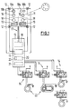
- Fig. 1 shows a schematic representation of an inventive Touch switch device.
- the touch switch device consists of the Control panel 11 with the sensors 12, the control device 13 and the Control device 13 controlled switching elements 14. It is subdivided the control device 13 into a detection and evaluation unit 15, in which the received sensor signals the position of the actuation of the control panel 11 the signals detected by the sensors 12 is determined.
- a Display control 16 may be provided, which is connected to the data bus 17 with the Panel 11 is connected, the panel being an LCD screen can act, which is also designed as a control panel and in which Via the display control unit 16 the marking of the buttons 18, 19 in Area of the button is marked visible to the user.
- Control device 13 has an assignment unit 20 in which both the assignment from position of actuation to button as well as the assignment of Button to switch function is made. Because of the as Switching function to be carried out is determined by the assignment unit 20 Signal sent to the power stage 21 of the control device 13. Controlled from the power level 21 different switching positions of the Switching elements 14 generated.
- the control panel can be formed, for example, from an LCD screen. Alternatively, it could also be in its surface as an area of the glass ceramic plate be formed a stove, on the underside corresponding Sensor elements are arranged.
- the control panel can be both a capacitive or a resistive one Act switching element that is sensitive to an external Touching the control panel works. According to the example shown, this is Panel 11 is rectangular and at each of the four corners of the panel a sensor is arranged. It would clearly determine the position of the Actuation of the control panel 11 is also sufficient to provide three sensors 12, which, for example, in a triangular shape within the area of the switch panel 11 could be arranged to uniquely determine the position of the actuation perform. Increasing the number of sensors 12 to a total of four increases the computing effort when determining the position of the actuation, but improves the measurement accuracy and also the resolution of the Touch switch device.
- the control panel 11 shown can be both a control panel that is designed as an LCD screen, and also act as a control panel that has other display means.
- the Surface of the control panel from the glass ceramic plate of a glass ceramic cooktop is formed. It is at the bottom of the glass ceramic plate that is on the inside, i.e. on the side where the heating elements are are arranged, a sensor device is attached.
- This sensor device consists for example of a number of transparent layers on the Underside of the glass ceramic plate are applied in the area of the control panel 11 and their capacitive or resistive properties due to touch change the surface of the glass ceramic plate in this area. there it may be necessary for a certain actuation force to be applied to the surface the glass ceramic surface is applied.
- the corresponding ones are also transparent trained touch switch known. Many of them work after that capacitive or resistive working principle. There are other working principles, for example the use of a signal generator and a signal receiver and the evaluation of the signal transit time or the received signal image (in particular optically, acoustically or electromagnetic) working touch sensors known that can also be used in the invention.
- the touch switch device is for the Intended for use in a stove.
- the control panel 11 is corresponding of the four hobs 22 present on this assumed stove in four Groups of buttons 18, 19 divided.
- Each group of buttons 18, 19 assigned to a hotplate.
- the groups of buttons 18, 19 are arranged on the control panel 11 and as electrical consumers Acting heaters assigned to the hotplates 22 that the arrangement the hotplates in the hob of the cooker the arrangement of the groups of Buttons in the panel corresponds.
- the area of a group of buttons on the control panel 11, depending on the size of the individual Cooking surfaces, for example proportional to it, can be determined.
- buttons 18, 19 consists of two elements in the example shown. It's a button 18 available, which may be divided into two buttons 18a and 18b and a button 19. The button 19 is in each case for determination the heating power is provided at a hotplate 22. With buttons 19 can be, for example, symbolized rotary knobs with different Act switching stages, whereby each switching stage is a button in itself forms. By pressing the corresponding button with the corresponding one Performance marking (performance levels 1 to 6) becomes the corresponding one Heating output selected.
- buttons 19 it is also possible to use the button 19 to symbolize in the manner of a pictogram that a volume is shown, the Selection of individual elements of the band is possible and so a push switch is faked.
- the push switch can be pulled by pulling on an appropriate one Position of a segment of the push switch selected in its performance become.
- a thrust switch or rotary knob realized in this way is in the sense this application as a button, although still different actuation positions can be realized.
- the button 18, or where available, the two buttons 18a, 18b serve the on / off switching function.
- This function can be used in a simple manner switch on or off the assigned heating device of the corresponding hotplate turned off. For example, it may be necessary for security reasons be to turn on a heater at the same time both the Button 18 or 18a and the associated button 19 for setting the Actuate heating power. This prevents accidental Touching the button at one point switches on a hotplate, which is disadvantageous if it happens unintentionally.
- a button 18a and 18b formed, the button 18a an auxiliary heating element and the button 18b the main heating element Cooking area is assigned.
- Cooking areas are known, in which in addition to one Main heating station can also be operated a secondary heating station can, the auxiliary heating point can only be switched on when the Main heating station is in operation.
- the auxiliary heating point is the same Power supplies like the main heating point. Therefore it is not necessary for that A separate power control circuit must be provided for the auxiliary heating point and therefore no separate button is necessary for this either.
- pressing the Button 18a can now switch on the corresponding auxiliary heating point become. Either by pressing button 18a again or by The operation of the secondary heating zone can be operated again by pressing the button surface 18b can be set so that only the main heating element of the corresponding Hotplate is in operation.
- the assignment between the position of the actuation of the control panel 11 and the corresponding button is carried out via the assignment unit 20.
- the assignment unit 20 can also the display control unit 16 influence, so that the display means of the control panel 11 depending on Operating state can be controlled.
- the part of the assignment unit in the selected example 20 is provided.
- the configuration means 23 can be, for example a series of dip switches act, for example, for each hotplate two dip switches are provided. With the first of the two dip switches the presence of an electrical consumer at the connection for the power control be signaled while on the position of the second dip switch the presence of a secondary consumer can be set.
- the hotplates differ in the number of electrical Consumers, i.e. the hot plates, can differentiate.
- the difference in Cooking areas can also be due to the fact that a different number of Ancillary consumers are present.
- the panel is divided 11 in buttons 18, 18, 18b and 19 depending on the am Configuration means 23 set configuration.
- Fig. 2 shows an exemplary schematic representation of the formation of a Hob with several hotplates 22.
- the hob 25 points as Finally up on the glass ceramic plate 26.
- the control panel 11 is made of glass ceramic plate. The control panel 11 is therefore part the hob 25.
- FIG. 3 shows a schematic representation of the determination of the position of the Operation by triangularization in the evaluation unit 15.
- the sensors 12a, 12b, 12c, 12d are arranged.
- the control panel 11 is actuated in each of the four sensors 12a, 12b, 12c, 12d the sensor signal changed.
- the change in the sensor signal is characteristic and dependent on the distance of the operating location to the sensor. It is usually a change in a voltage value or a current value, the sensor technology being either capacitive or resistive is working.
- a distance value Ua, Ub, Uc, Ud can be assigned to each voltage value be assigned.
- intersection of the four circles is now calculated determined that the respective sensor 12a, 12b, 12c, 12d with a radius of each surrounded by a line Ua, Ub, Uc, Ud. With a measurement error free
- the four circles should intersect at exactly one point. Since all Signals are subject to measurement inaccuracy and possible interference, there will not be a common intersection. Rather be several intersection points can be determined and then from these intersection points the middle can be determined, i.e. the place where the operation was probably carried out.
- each actuation of the control panel 11 becomes exactly one position assigned. From this position it can be determined whether they are in one of the Panels 18, 18a, 18b, 19 is located. If this is the case, the assigned electrical consumers associated with the actuation of the control panel Switching function carried out, for example the switching on or off of a Auxiliary heating element or an increase or decrease in heating power in the heating element itself.
Landscapes
- Chemical & Material Sciences (AREA)
- Engineering & Computer Science (AREA)
- Ceramic Engineering (AREA)
- Push-Button Switches (AREA)
- Electric Stoves And Ranges (AREA)
- Cookers (AREA)
- Switches That Are Operated By Magnetic Or Electric Fields (AREA)
- Coupling Device And Connection With Printed Circuit (AREA)
Applications Claiming Priority (2)
| Application Number | Priority Date | Filing Date | Title |
|---|---|---|---|
| DE10026058 | 2000-05-25 | ||
| DE10026058A DE10026058A1 (de) | 2000-05-25 | 2000-05-25 | Berührungsschalteinrichtung |
Publications (3)
| Publication Number | Publication Date |
|---|---|
| EP1158838A2 true EP1158838A2 (fr) | 2001-11-28 |
| EP1158838A3 EP1158838A3 (fr) | 2003-10-29 |
| EP1158838B1 EP1158838B1 (fr) | 2008-11-26 |
Family
ID=7643623
Family Applications (1)
| Application Number | Title | Priority Date | Filing Date |
|---|---|---|---|
| EP01112196A Expired - Lifetime EP1158838B1 (fr) | 2000-05-25 | 2001-05-18 | Dispositif de commutation commandé par effleurement |
Country Status (4)
| Country | Link |
|---|---|
| EP (1) | EP1158838B1 (fr) |
| AT (1) | ATE415801T1 (fr) |
| DE (2) | DE10026058A1 (fr) |
| ES (1) | ES2317861T3 (fr) |
Cited By (8)
| Publication number | Priority date | Publication date | Assignee | Title |
|---|---|---|---|---|
| EP1273851A3 (fr) * | 2001-07-07 | 2005-10-05 | Therma Grossküchen Produktion AG | Dispositif de commande pour appareil de cuisson |
| WO2005106335A3 (fr) * | 2004-04-28 | 2006-03-02 | Bsh Bosch Siemens Hausgeraete | Dispositif de reglage pourvu d'une zone de detection au moins bidimensionnelle |
| DE102004038872A1 (de) * | 2004-08-05 | 2006-03-16 | E.G.O. Elektro-Gerätebau GmbH | Kapazitiver Berührungsschalter für eine Bedieneinrichtung eines Elektrogeräts, Bedieneinrichtung sowie Verfahren zur Auswertung |
| WO2006048325A2 (fr) | 2004-11-08 | 2006-05-11 | E.G.O. Elektro-Gerätebau GmbH | Dispositif de commande, appareil electrique comprenant ledit dispositif de commande, ensemble pour un champ de cuisson ceramique comprenant ledit dispositif de commande et procede pour le faire fonctionner |
| WO2007036247A1 (fr) * | 2005-04-15 | 2007-04-05 | E.G.O. Elektro-Gerätebau GmbH | Procede pour commander et/ou evaluer un element de detection allonge d'un dispositif de commande, et dispositif de commande correspondant |
| FR2910744A1 (fr) * | 2006-12-26 | 2008-06-27 | Brandt Ind Sas | Procede de commande a touches sensitives, dispositif de commande et appareil domestique mettant en oeuvre un tel procede |
| FR2910745A1 (fr) * | 2006-12-26 | 2008-06-27 | Brandt Ind Sas | Procede d'illumination d'une surface d'un dispositif de commande a touches sensitives, dispositif de commande et table de cuisson mettant en oeuvre un tel procede |
| DE102013214162A1 (de) | 2013-07-18 | 2015-02-19 | E.G.O. Elektro-Gerätebau GmbH | Bedienteil für eine Bedieneinrichtung und Bedieneinrichtung |
Families Citing this family (8)
| Publication number | Priority date | Publication date | Assignee | Title |
|---|---|---|---|---|
| DE10342006C5 (de) * | 2003-09-04 | 2008-12-11 | E.G.O. Elektro-Gerätebau GmbH | Bedienvorrichtung |
| GB0323570D0 (en) | 2003-10-08 | 2003-11-12 | Harald Philipp | Touch-sensitivity control panel |
| DE102004008739A1 (de) * | 2004-02-23 | 2005-09-08 | BSH Bosch und Siemens Hausgeräte GmbH | Sensoreinrichtung für ein Haushaltsgerät |
| DE102007034703A1 (de) * | 2007-07-18 | 2009-01-22 | E.G.O. Elektro-Gerätebau GmbH | Bedieneinrichtung für ein Elektrogerät wie ein Kochfeld odgl. und Anordnung derselben |
| DE102008011659A1 (de) * | 2008-02-28 | 2009-09-03 | BSH Bosch und Siemens Hausgeräte GmbH | Kochfeld |
| DE102008032452A1 (de) * | 2008-07-10 | 2010-01-14 | Rational Ag | Anzeigeverfahren und Gargerät hierfür |
| DE102009039937A1 (de) * | 2009-08-25 | 2011-03-03 | E.G.O. Elektro-Gerätebau GmbH | Verfahren zur Eingabe eines zweistelligen Wertes an einer Bedieneinrichtung |
| DE102010062485B3 (de) | 2010-12-06 | 2012-04-26 | E.G.O. Elektro-Gerätebau GmbH | Verfahren zur Steuerung eines Gerätes und Bedieneinrichtung dafür |
Citations (1)
| Publication number | Priority date | Publication date | Assignee | Title |
|---|---|---|---|---|
| EP0443924A1 (fr) | 1990-02-19 | 1991-08-28 | Société SCHOLTES | Dispositif de commande des foyers de chauffage d'un appareil de cuisson, par touches sensitives |
Family Cites Families (10)
| Publication number | Priority date | Publication date | Assignee | Title |
|---|---|---|---|---|
| US4121204A (en) * | 1976-12-14 | 1978-10-17 | General Electric Company | Bar graph type touch switch and display device |
| CA1157925A (fr) * | 1979-09-28 | 1983-11-29 | Robert Posset | Panneaux de commutation a touches a effleurement capacitives et methodes de fabrication |
| IT1259215B (it) * | 1992-06-11 | 1996-03-11 | Zeltron Spa | Pannello di controllo per elettrodomestici |
| DE4243510A1 (de) * | 1992-12-22 | 1994-06-23 | Sel Alcatel Ag | Verfahren und Einrichtung zum Feststellen des Vorhandenseins und der Position von Baugruppen in einer Baueinheit |
| DE4407741C2 (de) * | 1994-03-08 | 1997-11-27 | Aeg Hausgeraete Gmbh | Einrichtung zum Ein- und Ausschalten eines elektrischen Verbrauchers |
| DE19615840A1 (de) * | 1996-04-20 | 1997-10-30 | Bosch Gmbh Robert | Elektrisches Hausgerät |
| DE29622066U1 (de) * | 1996-12-19 | 1998-04-16 | Aeg Hausgeraete Gmbh | Hausgerät mit einem Bedienpult |
| ES2151805B1 (es) * | 1998-03-16 | 2001-08-16 | Santis Danilo De | Sistema de control electronico de potencia para placas vitroceramicas de cocina con sensor optico de presencia de olla. |
| DE19849075A1 (de) * | 1998-10-24 | 2000-04-27 | Ego Elektro Geraetebau Gmbh | Steuerung für ein Elektrogerät |
| DE29908199U1 (de) * | 1999-05-03 | 1999-10-21 | Prokop, Joachim, Dipl.-Ing.Oek., 07616 Bürgel | Tischcomputer |
-
2000
- 2000-05-25 DE DE10026058A patent/DE10026058A1/de not_active Withdrawn
-
2001
- 2001-05-18 AT AT01112196T patent/ATE415801T1/de not_active IP Right Cessation
- 2001-05-18 EP EP01112196A patent/EP1158838B1/fr not_active Expired - Lifetime
- 2001-05-18 ES ES01112196T patent/ES2317861T3/es not_active Expired - Lifetime
- 2001-05-18 DE DE50114512T patent/DE50114512D1/de not_active Expired - Lifetime
Patent Citations (1)
| Publication number | Priority date | Publication date | Assignee | Title |
|---|---|---|---|---|
| EP0443924A1 (fr) | 1990-02-19 | 1991-08-28 | Société SCHOLTES | Dispositif de commande des foyers de chauffage d'un appareil de cuisson, par touches sensitives |
Cited By (11)
| Publication number | Priority date | Publication date | Assignee | Title |
|---|---|---|---|---|
| EP1273851A3 (fr) * | 2001-07-07 | 2005-10-05 | Therma Grossküchen Produktion AG | Dispositif de commande pour appareil de cuisson |
| WO2005106335A3 (fr) * | 2004-04-28 | 2006-03-02 | Bsh Bosch Siemens Hausgeraete | Dispositif de reglage pourvu d'une zone de detection au moins bidimensionnelle |
| DE102004038872A1 (de) * | 2004-08-05 | 2006-03-16 | E.G.O. Elektro-Gerätebau GmbH | Kapazitiver Berührungsschalter für eine Bedieneinrichtung eines Elektrogeräts, Bedieneinrichtung sowie Verfahren zur Auswertung |
| WO2006048325A2 (fr) | 2004-11-08 | 2006-05-11 | E.G.O. Elektro-Gerätebau GmbH | Dispositif de commande, appareil electrique comprenant ledit dispositif de commande, ensemble pour un champ de cuisson ceramique comprenant ledit dispositif de commande et procede pour le faire fonctionner |
| WO2006048325A3 (fr) * | 2004-11-08 | 2006-06-15 | Ego Elektro Geraetebau Gmbh | Dispositif de commande, appareil electrique comprenant ledit dispositif de commande, ensemble pour un champ de cuisson ceramique comprenant ledit dispositif de commande et procede pour le faire fonctionner |
| US7932481B2 (en) | 2004-11-08 | 2011-04-26 | E.G.O. Elektro-Geraetebau Gmbh | Operating device, electrical appliance with such an operating device, arrangement of a glass ceramic hob or an oven with such an operating device and method for operating such an operating device |
| WO2007036247A1 (fr) * | 2005-04-15 | 2007-04-05 | E.G.O. Elektro-Gerätebau GmbH | Procede pour commander et/ou evaluer un element de detection allonge d'un dispositif de commande, et dispositif de commande correspondant |
| FR2910744A1 (fr) * | 2006-12-26 | 2008-06-27 | Brandt Ind Sas | Procede de commande a touches sensitives, dispositif de commande et appareil domestique mettant en oeuvre un tel procede |
| FR2910745A1 (fr) * | 2006-12-26 | 2008-06-27 | Brandt Ind Sas | Procede d'illumination d'une surface d'un dispositif de commande a touches sensitives, dispositif de commande et table de cuisson mettant en oeuvre un tel procede |
| DE102013214162A1 (de) | 2013-07-18 | 2015-02-19 | E.G.O. Elektro-Gerätebau GmbH | Bedienteil für eine Bedieneinrichtung und Bedieneinrichtung |
| DE102013214162B4 (de) | 2013-07-18 | 2019-05-09 | E.G.O. Elektro-Gerätebau GmbH | Bedienteil für eine Bedieneinrichtung und Bedieneinrichtung |
Also Published As
| Publication number | Publication date |
|---|---|
| ATE415801T1 (de) | 2008-12-15 |
| DE50114512D1 (de) | 2009-01-08 |
| EP1158838A3 (fr) | 2003-10-29 |
| ES2317861T3 (es) | 2009-05-01 |
| EP1158838B1 (fr) | 2008-11-26 |
| DE10026058A1 (de) | 2001-11-29 |
Similar Documents
| Publication | Publication Date | Title |
|---|---|---|
| EP1158838B1 (fr) | Dispositif de commutation commandé par effleurement | |
| DE10133135B4 (de) | Stelleinheit für Gargeräte | |
| DE3837096C2 (de) | Leistungssteueranordnung für ein Glaskeramik-Kochfeld | |
| DE602004004953T2 (de) | Kochfeld mit Benutzerschnittstelle und beliebiger Positionierung | |
| EP1657819B1 (fr) | Commande de plaque de cuisson | |
| EP1876394B1 (fr) | Unité à curseur tactile avec une structure haptique en relief | |
| DE102004048463A1 (de) | Berührungs-sensitives Bedienfeld | |
| EP2065650B1 (fr) | Appareil ménager doté d'une interface utilisateur comprenant un élément de réglage | |
| EP2215408B1 (fr) | Appareil électroménager avec dispositif d'affichage | |
| DE102005018298A1 (de) | Verfahren zur Ansteuerung und/oder Auswertung eines länglichen Sensorelements einer Bedieneinrichtung und eine solche Bedieneinrichtung | |
| EP2758716A1 (fr) | Appareil de cuisson à zone de commande sensitive | |
| DE102005049995A1 (de) | Bedienvorrichtung für ein Elektrogerät und Bedienverfahren zur Bedienung eines Elektrogerätes | |
| EP2258987A2 (fr) | Appareil ménager doté d'un écran tactile | |
| EP1344983A2 (fr) | Arrangement pour le contrôle d'un plaque de cuisson | |
| EP1278016A2 (fr) | Organe de commande pour un appareil de cuisson | |
| EP1876515B1 (fr) | Dispositif de commande | |
| DE10125247C1 (de) | Haushaltsgerät mit einem Garraum | |
| WO2009010403A2 (fr) | Unité d'entrée d'appareil électroménager, en particulier pour une table de cuisson | |
| EP2258986A2 (fr) | Plaque de cuisson | |
| WO2003081411A2 (fr) | Ecran tactile | |
| DE10359561B4 (de) | Bedienelement für ein Haushaltsgerät | |
| DE4407741C2 (de) | Einrichtung zum Ein- und Ausschalten eines elektrischen Verbrauchers | |
| DE102005041028A1 (de) | Elektronisch gesteuertes Kochfeld mit mehreren Kochstellen und Verfahren zum Betrieb eines solchen Kochfeldes | |
| EP2896889B1 (fr) | Procédé destiné au fonctionnement d'un appareil de cuisson avec une plaque de cuisson et appareil de cuisson | |
| EP2708818A2 (fr) | Dispositif de champ de cuisson |
Legal Events
| Date | Code | Title | Description |
|---|---|---|---|
| PUAI | Public reference made under article 153(3) epc to a published international application that has entered the european phase |
Free format text: ORIGINAL CODE: 0009012 |
|
| AK | Designated contracting states |
Kind code of ref document: A2 Designated state(s): AT BE CH CY DE DK ES FI FR GB GR IE IT LI LU MC NL PT SE TR |
|
| AX | Request for extension of the european patent |
Free format text: AL;LT;LV;MK;RO;SI |
|
| PUAL | Search report despatched |
Free format text: ORIGINAL CODE: 0009013 |
|
| AK | Designated contracting states |
Kind code of ref document: A3 Designated state(s): AT BE CH CY DE DK ES FI FR GB GR IE IT LI LU MC NL PT SE TR |
|
| AX | Request for extension of the european patent |
Extension state: AL LT LV MK RO SI |
|
| RIC1 | Information provided on ipc code assigned before grant |
Ipc: 7H 05B 3/74 A Ipc: 7F 24C 7/08 B |
|
| 17P | Request for examination filed |
Effective date: 20031115 |
|
| 17Q | First examination report despatched |
Effective date: 20040305 |
|
| AKX | Designation fees paid |
Designated state(s): AT BE CH CY DE DK ES FI FR GB GR IE IT LI LU MC NL PT SE TR |
|
| GRAP | Despatch of communication of intention to grant a patent |
Free format text: ORIGINAL CODE: EPIDOSNIGR1 |
|
| GRAS | Grant fee paid |
Free format text: ORIGINAL CODE: EPIDOSNIGR3 |
|
| GRAA | (expected) grant |
Free format text: ORIGINAL CODE: 0009210 |
|
| AK | Designated contracting states |
Kind code of ref document: B1 Designated state(s): AT BE CH CY DE DK ES FI FR GB GR IE IT LI LU MC NL PT SE TR |
|
| REG | Reference to a national code |
Ref country code: GB Ref legal event code: FG4D Free format text: NOT ENGLISH |
|
| REG | Reference to a national code |
Ref country code: CH Ref legal event code: EP |
|
| REG | Reference to a national code |
Ref country code: IE Ref legal event code: FG4D Free format text: LANGUAGE OF EP DOCUMENT: GERMAN |
|
| REF | Corresponds to: |
Ref document number: 50114512 Country of ref document: DE Date of ref document: 20090108 Kind code of ref document: P |
|
| REG | Reference to a national code |
Ref country code: CH Ref legal event code: NV Representative=s name: ZIMMERLI, WAGNER & PARTNER AG |
|
| REG | Reference to a national code |
Ref country code: ES Ref legal event code: FG2A Ref document number: 2317861 Country of ref document: ES Kind code of ref document: T3 |
|
| NLV1 | Nl: lapsed or annulled due to failure to fulfill the requirements of art. 29p and 29m of the patents act | ||
| PG25 | Lapsed in a contracting state [announced via postgrant information from national office to epo] |
Ref country code: NL Free format text: LAPSE BECAUSE OF FAILURE TO SUBMIT A TRANSLATION OF THE DESCRIPTION OR TO PAY THE FEE WITHIN THE PRESCRIBED TIME-LIMIT Effective date: 20081126 Ref country code: FI Free format text: LAPSE BECAUSE OF FAILURE TO SUBMIT A TRANSLATION OF THE DESCRIPTION OR TO PAY THE FEE WITHIN THE PRESCRIBED TIME-LIMIT Effective date: 20081126 |
|
| REG | Reference to a national code |
Ref country code: IE Ref legal event code: FD4D |
|
| PG25 | Lapsed in a contracting state [announced via postgrant information from national office to epo] |
Ref country code: DK Free format text: LAPSE BECAUSE OF FAILURE TO SUBMIT A TRANSLATION OF THE DESCRIPTION OR TO PAY THE FEE WITHIN THE PRESCRIBED TIME-LIMIT Effective date: 20081126 Ref country code: IE Free format text: LAPSE BECAUSE OF FAILURE TO SUBMIT A TRANSLATION OF THE DESCRIPTION OR TO PAY THE FEE WITHIN THE PRESCRIBED TIME-LIMIT Effective date: 20081126 |
|
| PLBI | Opposition filed |
Free format text: ORIGINAL CODE: 0009260 |
|
| PG25 | Lapsed in a contracting state [announced via postgrant information from national office to epo] |
Ref country code: PT Free format text: LAPSE BECAUSE OF FAILURE TO SUBMIT A TRANSLATION OF THE DESCRIPTION OR TO PAY THE FEE WITHIN THE PRESCRIBED TIME-LIMIT Effective date: 20090427 Ref country code: SE Free format text: LAPSE BECAUSE OF FAILURE TO SUBMIT A TRANSLATION OF THE DESCRIPTION OR TO PAY THE FEE WITHIN THE PRESCRIBED TIME-LIMIT Effective date: 20090226 |
|
| PLAX | Notice of opposition and request to file observation + time limit sent |
Free format text: ORIGINAL CODE: EPIDOSNOBS2 |
|
| 26 | Opposition filed |
Opponent name: AEG HAUSGERAETE GMBH Effective date: 20090824 |
|
| REG | Reference to a national code |
Ref country code: CH Ref legal event code: PFA Owner name: E.G.O. ELEKTRO-GERAETEBAU GMBH Free format text: E.G.O. ELEKTRO-GERAETEBAU GMBH#ROTE-TOR-STRASSE 14#75038 OBERDERDINGEN (DE) -TRANSFER TO- E.G.O. ELEKTRO-GERAETEBAU GMBH#ROTE-TOR-STRASSE 14#75038 OBERDERDINGEN (DE) |
|
| BERE | Be: lapsed |
Owner name: E.G.O. ELEKTRO-GERATEBAU G.M.B.H. Effective date: 20090531 |
|
| PG25 | Lapsed in a contracting state [announced via postgrant information from national office to epo] |
Ref country code: MC Free format text: LAPSE BECAUSE OF NON-PAYMENT OF DUE FEES Effective date: 20090531 |
|
| GBPC | Gb: european patent ceased through non-payment of renewal fee |
Effective date: 20090518 |
|
| PLBB | Reply of patent proprietor to notice(s) of opposition received |
Free format text: ORIGINAL CODE: EPIDOSNOBS3 |
|
| PG25 | Lapsed in a contracting state [announced via postgrant information from national office to epo] |
Ref country code: GB Free format text: LAPSE BECAUSE OF NON-PAYMENT OF DUE FEES Effective date: 20090518 |
|
| PG25 | Lapsed in a contracting state [announced via postgrant information from national office to epo] |
Ref country code: BE Free format text: LAPSE BECAUSE OF NON-PAYMENT OF DUE FEES Effective date: 20090531 |
|
| PG25 | Lapsed in a contracting state [announced via postgrant information from national office to epo] |
Ref country code: AT Free format text: LAPSE BECAUSE OF NON-PAYMENT OF DUE FEES Effective date: 20090518 |
|
| PG25 | Lapsed in a contracting state [announced via postgrant information from national office to epo] |
Ref country code: GR Free format text: LAPSE BECAUSE OF FAILURE TO SUBMIT A TRANSLATION OF THE DESCRIPTION OR TO PAY THE FEE WITHIN THE PRESCRIBED TIME-LIMIT Effective date: 20090227 |
|
| PG25 | Lapsed in a contracting state [announced via postgrant information from national office to epo] |
Ref country code: LU Free format text: LAPSE BECAUSE OF NON-PAYMENT OF DUE FEES Effective date: 20090518 |
|
| PG25 | Lapsed in a contracting state [announced via postgrant information from national office to epo] |
Ref country code: CY Free format text: LAPSE BECAUSE OF FAILURE TO SUBMIT A TRANSLATION OF THE DESCRIPTION OR TO PAY THE FEE WITHIN THE PRESCRIBED TIME-LIMIT Effective date: 20081126 |
|
| PLAB | Opposition data, opponent's data or that of the opponent's representative modified |
Free format text: ORIGINAL CODE: 0009299OPPO |
|
| R26 | Opposition filed (corrected) |
Opponent name: ELECTROLUX ROTHENBURG GMBH FACTORY AND DEVELOPMENT Effective date: 20090824 |
|
| APBM | Appeal reference recorded |
Free format text: ORIGINAL CODE: EPIDOSNREFNO |
|
| APBP | Date of receipt of notice of appeal recorded |
Free format text: ORIGINAL CODE: EPIDOSNNOA2O |
|
| APAH | Appeal reference modified |
Free format text: ORIGINAL CODE: EPIDOSCREFNO |
|
| APAJ | Date of receipt of notice of appeal modified |
Free format text: ORIGINAL CODE: EPIDOSCNOA2O |
|
| APBM | Appeal reference recorded |
Free format text: ORIGINAL CODE: EPIDOSNREFNO |
|
| APBP | Date of receipt of notice of appeal recorded |
Free format text: ORIGINAL CODE: EPIDOSNNOA2O |
|
| APBQ | Date of receipt of statement of grounds of appeal recorded |
Free format text: ORIGINAL CODE: EPIDOSNNOA3O |
|
| REG | Reference to a national code |
Ref country code: CH Ref legal event code: NV Representative=s name: WAGNER PATENT AG, CH |
|
| PGFP | Annual fee paid to national office [announced via postgrant information from national office to epo] |
Ref country code: TR Payment date: 20140512 Year of fee payment: 14 Ref country code: IT Payment date: 20140520 Year of fee payment: 14 Ref country code: CH Payment date: 20140522 Year of fee payment: 14 Ref country code: DE Payment date: 20140527 Year of fee payment: 14 Ref country code: ES Payment date: 20140521 Year of fee payment: 14 Ref country code: FR Payment date: 20140516 Year of fee payment: 14 |
|
| REG | Reference to a national code |
Ref country code: DE Ref legal event code: R119 Ref document number: 50114512 Country of ref document: DE |
|
| REG | Reference to a national code |
Ref country code: CH Ref legal event code: PL |
|
| PG25 | Lapsed in a contracting state [announced via postgrant information from national office to epo] |
Ref country code: IT Free format text: LAPSE BECAUSE OF NON-PAYMENT OF DUE FEES Effective date: 20150518 Ref country code: LI Free format text: LAPSE BECAUSE OF NON-PAYMENT OF DUE FEES Effective date: 20150531 Ref country code: CH Free format text: LAPSE BECAUSE OF NON-PAYMENT OF DUE FEES Effective date: 20150531 |
|
| REG | Reference to a national code |
Ref country code: FR Ref legal event code: ST Effective date: 20160129 |
|
| PG25 | Lapsed in a contracting state [announced via postgrant information from national office to epo] |
Ref country code: DE Free format text: LAPSE BECAUSE OF NON-PAYMENT OF DUE FEES Effective date: 20151201 |
|
| PG25 | Lapsed in a contracting state [announced via postgrant information from national office to epo] |
Ref country code: FR Free format text: LAPSE BECAUSE OF NON-PAYMENT OF DUE FEES Effective date: 20150601 |
|
| REG | Reference to a national code |
Ref country code: ES Ref legal event code: FD2A Effective date: 20160624 |
|
| PG25 | Lapsed in a contracting state [announced via postgrant information from national office to epo] |
Ref country code: ES Free format text: LAPSE BECAUSE OF NON-PAYMENT OF DUE FEES Effective date: 20150519 |
|
| PG25 | Lapsed in a contracting state [announced via postgrant information from national office to epo] |
Ref country code: TR Free format text: LAPSE BECAUSE OF NON-PAYMENT OF DUE FEES Effective date: 20150518 |
|
| REG | Reference to a national code |
Ref country code: DE Ref legal event code: R100 Ref document number: 50114512 Country of ref document: DE |
|
| APBU | Appeal procedure closed |
Free format text: ORIGINAL CODE: EPIDOSNNOA9O |
|
| REG | Reference to a national code |
Ref country code: DE Ref legal event code: R100 Ref document number: 50114512 Country of ref document: DE |
|
| PLBD | Termination of opposition procedure: decision despatched |
Free format text: ORIGINAL CODE: EPIDOSNOPC1 |
|
| PLBM | Termination of opposition procedure: date of legal effect published |
Free format text: ORIGINAL CODE: 0009276 |
|
| 27C | Opposition proceedings terminated |
Effective date: 20171121 |
|
| PLAD | Information related to termination of opposition procedure modified |
Free format text: ORIGINAL CODE: 0009299OPPC |
|
| STAA | Information on the status of an ep patent application or granted ep patent |
Free format text: STATUS: OPPOSITION PROCEDURE CLOSED |
|
| R27C | Opposition proceedings terminated (corrected) |
Effective date: 20171221 |