EP1159224B1 - Schüttgutdosiervorrichtung mit seitlich entfernbarem trichter - Google Patents
Schüttgutdosiervorrichtung mit seitlich entfernbarem trichter Download PDFInfo
- Publication number
- EP1159224B1 EP1159224B1 EP00908528A EP00908528A EP1159224B1 EP 1159224 B1 EP1159224 B1 EP 1159224B1 EP 00908528 A EP00908528 A EP 00908528A EP 00908528 A EP00908528 A EP 00908528A EP 1159224 B1 EP1159224 B1 EP 1159224B1
- Authority
- EP
- European Patent Office
- Prior art keywords
- hopper
- feed hopper
- extension
- axis
- support structure
- Prior art date
- Legal status (The legal status is an assumption and is not a legal conclusion. Google has not performed a legal analysis and makes no representation as to the accuracy of the status listed.)
- Expired - Lifetime
Links
Images





Classifications
-
- B—PERFORMING OPERATIONS; TRANSPORTING
- B65—CONVEYING; PACKING; STORING; HANDLING THIN OR FILAMENTARY MATERIAL
- B65D—CONTAINERS FOR STORAGE OR TRANSPORT OF ARTICLES OR MATERIALS, e.g. BAGS, BARRELS, BOTTLES, BOXES, CANS, CARTONS, CRATES, DRUMS, JARS, TANKS, HOPPERS, FORWARDING CONTAINERS; ACCESSORIES, CLOSURES, OR FITTINGS THEREFOR; PACKAGING ELEMENTS; PACKAGES
- B65D88/00—Large containers
- B65D88/26—Hoppers, i.e. containers having funnel-shaped discharge sections
- B65D88/28—Construction or shape of discharge section
-
- B—PERFORMING OPERATIONS; TRANSPORTING
- B65—CONVEYING; PACKING; STORING; HANDLING THIN OR FILAMENTARY MATERIAL
- B65D—CONTAINERS FOR STORAGE OR TRANSPORT OF ARTICLES OR MATERIALS, e.g. BAGS, BARRELS, BOTTLES, BOXES, CANS, CARTONS, CRATES, DRUMS, JARS, TANKS, HOPPERS, FORWARDING CONTAINERS; ACCESSORIES, CLOSURES, OR FITTINGS THEREFOR; PACKAGING ELEMENTS; PACKAGES
- B65D90/00—Component parts, details or accessories for large containers
- B65D90/02—Wall construction
- B65D90/08—Interconnections of wall parts; Sealing means therefor
Definitions
- This invention relates to bulk material metering systems according to the preamble of claim 1.
- Bulk-solid metering systems are used to feed finely divided (powdered or granular) material into processing equipment.
- the processing equipment fed by the metering system uses the material as the sole constituent or as one of the constituents in the intermediate or final product to be made.
- a bulk-solid metering system deliver a precisely-measured amount of material for each unit, e.g., minute or hour, of operating time.
- Sophisticated gravimetric and volumetric measuring systems have been developed to help assure the bulk-solid metering system performs in this way. Examples of bulk-solid metering systems are disclosed in U.S. Patent Nos. 4,804,111 (Ricciardi et al.
- a bulk-solid metering system in the US 5 265 763 is a bulk-solid metering system, according to the preamble of claim 1, described, which comprises a support structure for supporting an extension hopper and a feed hopper mounted with respect thereto.
- the support structure extends along a substantially vertical axis and includes an upper wall defining an aperture adapted to receive the extension hopper mounted with respect thereto.
- the extension hopper has an upper material inlet, a lower material outlet and an extension hopper flange, said extension hopper being removable mounted with respect to the upper wall such that, when mounted, the extension hopper extends at least partially through the upper wall aperture and the extension hopper flange is located below the upper wall.
- the feed hopper has an upper material inlet, a lower material outlet and a feed hopper flange.
- the feed hopper is removable mounted with respect to the support structure by detachable engagement of the extension hopper and feed hopper flanges such that when mounted, the feed hopper upper material inlet is in material-flow relationship with the extension hopper lower material outlet.
- the feed hopper is movable completely into and out of the support structure.
- An auger is rotatably mounted in a duct to move the bulk solid material from the duct top opening which is in material-flow relationship with the feed hopper material outlet. Said auger and duct are movable separately from the mounted feed hopper and support structure.
- a drive unit is mounted with respect to the support structure on the same pivotable mount adapted to permit the drive unit to move in power transmission relationship with the mounted auger such that the drive unit rotates the auger.
- the drive unit and the auger are pivoted away from the feed hopper such that the feed hopper is free to fully withdrawn from the support structure.
- a commercial bakery may employ several bulk-solid metering systems to feed one or more types of flour and other ingredients into a large machine for mixing bread dough. It is not unusual to automate the installation so that the operator can program which metering systems are to be operated and the feed rates therefor in order to make a particular type of bread.
- a manufacturer of pharmaceutical products may use plural bulk-solid metering systems to feed active and inert ingredients to a powder mixer.
- the powder mixer feeds what might be termed a pelletizing machine, the final output product.of which is tablets.
- Conventional bulk-solid metering systems are characterized by a support structure to which is secured a cone-like, wide-mouth feed hopper.
- a conveyor embodied as a screw or auger rotating in a duct.
- the auger feeds the material in the hopper outwardly through the duct and the hopper spout to the processing equipment.
- the hoppers may be made of rigid or flexible substance and, if made of the latter, the system also includes paddles to agitate the hopper and help assure continuous flow of material in the hopper.
- extension hopper mounted to and above the feed hopper.
- the extension hopper increases the overall hopper capacity and where the hoppers are filled by batch filling from, e.g., an overhead crane, using two hoppers is significantly more efficient.
- the feed hopper is configured with ease of system fabrication and ease of hopper sidewall agitation in mind.
- hopper shape which, in horizontal cross-section, is rectangular along substantially the entire hopper height. Fabrication is easy since the feed hopper support frame is, itself, likely to be rectangular. And flat hopper sidewalls are or may be easier to make than curved sidewalls. Further, external agitation paddles work well against flat sidewalls.
- a rectangular-section hopper is very easy to "transition" from a wide rectangular mouth to the narrow slot-like opening in which the conveying auger is mounted.
- the feed hopper substantially free of material from the previous batch before the next batch is “charged” into such hopper.
- Some types of food and pharmaceutical materials deteriorate over time; “first in, first out” material management helps avoid incorporating deteriorated material into the product being made.
- An object of the invention is to provide an improved bulk-solid metering system, according to claim 1, which addresses problems and shortcomings of earlier systems.
- Another object of the invention is to provide an improved bulk-solid metering system which simplifies certain aspects of system repair and maintenance.
- Another object of the invention is to provide an improved bulk-solid metering system which better promotes mass flow.
- Yet another object of the invention is to provide an improved bulk-solid metering system which lends itself well to feed hopper agitation. How these and other objects are accomplished will become apparent from the following descriptions and from the drawings.
- the invention involves a bulk-solid metering system of the type having a support structure and a feed hopper mounted with respect to the structure and having an upper edge.
- the structure includes an upper member and the upper edge of the feed hopper is below the upper member.
- the structure defines a lateral opening sized and shaped to permit the feed hopper to be withdrawn laterally through the opening.
- a significant advantage of the arrangement is that the feed hopper can be serviced without removing any extension hopper which may be attached thereto. Another advantage is that if the feed hopper needs to be removed, the nozzle between the feed hopper spout and the process equipment being fed by the system need not be moved or, at most, needs only minimal time and effort to disconnect such nozzle from the hopper.
- the support structure extends along a substantially vertical axis.
- the feed hopper includes a spout which extends from the hopper body along a first axis away from the vertical axis.
- the lateral opening is positioned to permit withdrawal of the feed hopper away from the vertical axis and along a second axis.
- the spout and the lateral opening are positioned with respect to one another so that the first axis and the second axis are about 180° apart.
- the feed hopper may be made of a flexible material or of rigid sheet metal.
- the system include a feed hopper agitator or stirring system, respectively.
- a feed hopper agitator or stirring system With a flexible feed hopper, two such agitators are usually used and they periodically "jar” or push against opposite sides of the body of the feed hopper to help keep the material therein from “bridging” or “ratholing” and impairing smooth flow.
- the agitators are mounted for reciprocating movement along an agitator axis angled with respect to the second axis.
- the agitator axis and the second axis are substantially perpendicular to one another.
- Yet other aspects of the new system relate to the ability to remove the feed hopper without removing the extension hopper.
- An extension hopper mounted in material-feeding relationship to the feed hopper and the hoppers are joined to one another at a hopper joint.
- the hopper joint is below the upper member of the support structure.
- the feed hopper includes an upper or first flange
- the extension hopper includes a second flange
- a securing device is in overlapping relationship to the flanges, thereby fastening the hoppers to one another.
- the securing device is a circular hoop which overlaps with and engages both flanges.
- the body of the feed hopper is made of a flexible material.
- the first flange is made of a rigid material and is secured to the hopper body by such flexible material. That is, the rigid first flange is molded into the material which permanently bonds.
- a resilient sealing ring is compressed between the flanges and the extension hopper has a mounting member, e.g., a circular ring, removably affixed to the upper member of the support structure.
- the feed and extension hoppers can be easily joined to by the extension hopper and includes a drive unit, a stirring device and a power shaft extending between the drive unit and the stirring device.
- the power shaft is mounted for movement with respect to the feed hopper, thereby permitting the stirring device to be removed from the feed hopper.
- the drive unit and the power shaft are coupled to one another by a coupling.
- the preferred coupling holds the stirring device at a predetermined location in the feed hopper and yet permits sliding movement of the power shaft in the drive unit.
- the sliding coupling also permits the power shaft to move upwardly through the drive unit. The system user can thereby raise the stirring device to the elevation necessary to "clear" the feed hopper as such hopper is withdrawn.
- FIGURE 1 illustrates a prior art process arrangement 201 which has several bulk-solid metering systems 203 mounted side by side.
- Each such system 203 includes an auxiliary hopper 205 above a respective system feed hopper 207.
- the feed hoppers 207 extend downwardly into respective housings 209 and terminate in a spout in which an auger or other conveyor operates.
- Each auger urges material from a respective feed hopper 207 into a multi-branch pipeline 211 which feeds such material into the process equipment.
- Such equipment may be, e.g., mixing powder additives for paint, making multi-constituent pelletized products or the like.
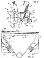
- the bulk-solid metering system 10 has a support structure 11 extending upwardly from the floor along a substantially vertical axis 13.
- the structure 11 comprises a pair of opposed support columns 15, 17, each coupled through a load cell housing (for gravimetric applications) or through a mounting block (for volumetric applications) to an opposed sidewall 19.
- Each sidewall 19 has a support pad 21 extending inwardly therefrom and such pads 21 and sidewalls 19 support reciprocating, opposed feed hopper agitators 23 and the drive mechanism 25 therefor.
- An upper member 27 spans and is attached to the sidewalls 19 and has a central aperture 29 through it.
- the structure 11 also supports a feed hopper 31 and an extension hopper 33 in a manner described below.
- the feed hopper 31 has an upper edge 34 configured to include an upper or first flange 35. While the hopper body 37 is (in one embodiment) made of a flexible plastic material, the flange 35 is made of a rigid material, e.g., steel, which is molded into the plastic material. As particularly shown in FIGURES 5 and 6 , the upper edge 34 of the feed hopper is spaced somewhat below the upper member 27.
- the hopper body 37 tapers downwardly and inwardly to form a laterally extending duct 39 at the bottom of the hopper 31.
- the duct 39 is generally cylindrical and top-opening so the auger rotating in the duct 39 may receive the material flowing downwardly in the hopper and urge such material out of the hopper spout 43.
- An extension piece often referred to as a nozzle 45, is attached to the spout 43 and secured on the structure wall 47 by a clamp 49. Material urged out of the spout 43 by the auger 41 flows along the nozzle 45 and to the process equipment in which the material is being used.
- the feed hopper body 37 has a circular upper flow portion 51 and opposed, flat agitator portions 53 extending downwardly from the portion 51.
- Such body 37 has a first cross-sectional shape adjacent to the upper flange 35 and a second, different cross-sectional shape intermediate the upper flange and the spout.
- the first cross-sectional shape 55 is circular (as shown in FIGURE 9 ), thereby availing the user of very good mass flow characteristics.
- the second cross-sectional shape 57, shown in FIGURE 10 is other than circular.
- such shape 57 has a longitudinal axis 59 and a lateral axis 61 perpendicular to and shorter than the longitudinal axis 59.
- Such shape 57 is "race-track-like" in that it has rounded or half-circle ends 63 joined by parallel straight sides 65.
- the longitudinal axis 59 of the second cross-sectional shape 57 is substantially parallel to the spout axis 67, also referred to herein as the spout first axis 67.
- the support structure 11 defines a lateral opening 69 sized and shaped to permit the feed hopper 31 to be withdrawn laterally through the opening 69.
- the opening 69 is positioned to permit withdrawal of the feed hopper 31 away from the vertical axis 13 and along a second axis 71.
- the spout 43 and the lateral opening 69 are positioned with respect to one another so that the first axis 67 and the second axis 71 are about 180° apart.
- the system 10 includes a feed hopper agitator 23 and, usually, two such agitators 23 (one of which is omitted in FIGURE 5 ) which periodically "jar” or push against opposite portions 53 of the flexible body 37. Such agitation helps keep the material in the hopper 31 from “bridging” or “ratholing” and impairing smooth flow.
- the agitators 23 are mounted for reciprocating movement along an agitator axis 73 angled with respect to the second axis 71 and, most preferably, perpendicular to and spaced above such second axis 71. It is to be appreciated that the agitator portions 53 are flat.
- the agitators 23 can be positioned (in their sequence of positions assumed during agitation) so that such agitators 23 are spaced slightly from the portions 53 to provide clearance for the hopper 31, the presence of the agitators 23 does not impair lateral withdrawal of the hopper 31.
- an extension hopper 33 is mounted in material-feeding relationship to the feed hopper 31 and includes a mounting component 75.
- Such component 75 has a circular mounting ring 77, a circular extension hopper flange 79 spaced below the ring 77 and a cylinder-like component body 81 extending between and rigidly joining the ring 77 and the flange 79.
- the diameters of the mounting ring 77 and the aperture 29 in the upper support member 27 are cooperatively selected so that the ring 77 sits atop such member 27 and cannot pass through the aperture 29.
- the extension hopper 33 is mounted to the member 27 by fasteners, e.g., bolts or the like, extending through the ring 77 and the member 27.
- the diameters of the aperture 29 and the flange 79 are selected so that the flange 79 is laterally coextensive with the feed hopper flange 35 and the flange 79 "clears" the aperture 29 and can be lifted out therethrough when the extension 33 hopper is removed from the support structure.
- aperture 29 and flanges 35, 79 which are round are preferred.
- an aperture and flanges having other shapes may be used.
- the hoppers 31, 33 are joined to one another at a hopper joint 83 which is below the upper member 27 of the support structure 11. And as noted above, the flange 35 of the hopper 31 is below such member 27.
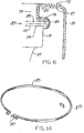
- a securing device 85 is in overlapping relationship to the flanges 35, 79, thereby fastening the hoppers 31, 33 to one another.
- the securing device 85 is a circular hoop which overlaps with both flanges 35, 79 and, when the securing bolt 87 (or other suitable securing mechanism, e.g., a toggle latch) is tightened, the device 85 secures both flanges 35, 79 to one another.
- a resilient seal ring 89 between the flanges 35, 79.
- the ring 89 is molded integrally with the body 37 and the flange 35. But where the hopper 31 is rigid, such ring 89 is a separate component.
- the extension hopper 33 has an upper edge 91 and a lower mouth 93.
- the cross-sectional shape of the extension hopper 33 is circular.
- the feed hopper 31 includes a driven conveyor such as the auger 41 mentioned above.
- a conveyor drive unit 95 e.g., an electric motor 97 and speed reducer 99, is supported by the structure 11. While the drive unit 95 may take any of a number of configurations and be mounted in any of several ways (some of which may not obstruct the lateral opening 69), a preferred way is to mount the unit 95 for pivoting movement between a conveyor drive position shown in FIGURE 2 and a hopper-removing position shown in FIGURE 4 .
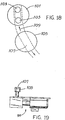
- the auger 41 includes an auger-driving shaft 101 having a pair of drive studs 103 protruding therefrom and the drive unit 95 includes a rotating drive head 105 which has a slot 107 to engage the studs 103.
- the studs 103 and slot 107 are cooperatively sized and located so that the slot 107 may come into registry with and engage the studs 103 when the drive unit 95 is pivoted in the direction indicated by the arrow 109.
- a significant advantage of the new system 10 is that the feed hopper 31 can be removed for hopper or auger maintenance without removing any extension hopper 33 which may be attached thereto. Another advantage is that if the feed hopper 31 needs to be removed, the nozzle 45 between the feed hopper 31 and the process equipment being fed by the system 10 need not be moved or, at most, needs only minimal time and effort to disconnect such nozzle 45 from the hopper 31. And the feed and extension hoppers 31, 33 can be easily joined to one another and, just as easily, the extension hopper 33 can be removed from the support structure 11, if necessary.
- the feed hopper 31 is made of a rigid material, e.g., stainless steel, rather than of a flexible material.
- the extension hopper 33 is also made of stainless steel as in the embodiment of FIGURES 2-4 .
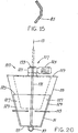
- a preferred feed hopper 31 is shaped like an inverted truncated cone. That is, such hopper has a sidewall which tapers inwardly and downwardly and which is of circular cross-sectional shape along substantially all of its height. But for the duct 39 described above, the hopper bottom 111 is substantially flat and perpendicular to the vertical axis 13.
- the structure at 113 represents the upper flange 35 of the feed hopper 31.
- the stirring mechanism 115 includes a drive unit 117 supported by and atop a cover 119 on the extension hopper 33.
- Such drive unit 117 includes a right-angle speed reducer 121, preferably of the hollow shaft type, and an electric drive motor 123.
- a stirring device 125 is used to promote mass flow and an exemplary device 125 includes a pair of radially extending blades 127. The blade edges 129 are located and configured to closely conform to the shape of the hopper 31 while yet avoiding contacting such hopper 31 along either the sidewall or the bottom.
- An elongated power shaft 131 is rigidly affixed to the stirring device 125, extends upwardly and is in driven engagement with the drive unit 117.
- the shaft 131 cannot rotate independently of the speed reducer 121 but is configured to slide axially therewithin. (As examples, a'key or spline coupling meets these parameters.)
- the stirring device 125 (with its shaft 131) are, during operation, held at predetermined locations, shown in FIGURE 20 in solid outline, in the feed hopper 31. And when it is desired to withdraw the feed hopper 31, the collar 133 is loosened, the stirring device 125 and shaft 131 raised to the positions shown in FIGURE 20 in dashed outline, and the collar 133 re-tightened. This not only removes the stirring device 125 from the feed hopper 31, it also conveniently holds such device 125 in an elevated position, pending completion of service work.
Landscapes
- Engineering & Computer Science (AREA)
- Mechanical Engineering (AREA)
- Filling Or Emptying Of Bunkers, Hoppers, And Tanks (AREA)
- Sampling And Sample Adjustment (AREA)
- Feeding, Discharge, Calcimining, Fusing, And Gas-Generation Devices (AREA)
- Preliminary Treatment Of Fibers (AREA)
- Weight Measurement For Supplying Or Discharging Of Specified Amounts Of Material (AREA)
Claims (19)
- Schüttgutdosiersystem (10), das folgende Komponenten umfasst:- einen Aufsatzbehälter (33) mit einem Materialeinlauf am oberen und einem Materialauslauf am unteren Ende,- einen Dosierbehälter (31) mit einem Materialeinlauf am oberen und einem Materialauslauf am unteren Ende sowie einem ersten Flansch (35) und einem entlang einer ersten Achse (67) verlaufenden Auslaufkanal (39), der oben eine Öffnung hat, die durch den Materialfluss mit dem unteren Materialauslauf in Verbindung steht,- eine Stützkonstruktion (11) zur Abstützung des Aufsatzbehälters (33) und des entlang einer im Wesentlichen vertikal verlaufenden Achse (13) daran angebauten Dosierbehälters (31), die ein Deckblech (27) mit einer zentralen Öffnung (29) aufweist, die für die Aufnahme des in der Stützkonstruktion gelagerten Aufsatzbehälters (33) ausgebildet ist,- eine im Auslaufkanal (39) drehbar gelagerte Schnecke (41), die das von der Öffnung an der Oberseite des Auslaufkanals kommende Material weitertransportiert sowie eine- Antriebsvorrichtung (95),
wobei der Aufsatzbehälter (33) gegenüber dem Deckblech (27) abnehmbar und so aufgesetzt ist, dass er im aufgesetzten Zustand zumindest teilweise durch die Öffnung (29) im Deckblech hindurchragt, und wobei der Dosierbehälter (31) durch eine lösbare Verbindung des Aufsatzbehälters (33) und des ersten Flansches von der Stützkonstruktion (11) abnehmbar ist, derart, dass1) der Dosierbehälter (31) in eingesetztem Zustand in einem Aufnahmeraum sitzt und der Materialeinlass am oberen Ende des Dosierbehälters mit dem Materialauslass am unteren Ende des Aufsatzbehälters durch den Materialfluss in Verbindung steht und2) der Dosierbehälter (31) im abgenommenen Zustand vollständig in die Stützkonstruktiondadurch gekennzeichnet, dass
hinein- bzw. aus dieser herausbewegt werden kann,- eine erste und eine zweite Seitenwand (19), die gegenüberliegend voneinander angeordnet sind, beide am Deckblech (27) befestigt sind,- sich dazwischen eine an den Seitenwänden (19) befestigte Querwand (47) erstreckt, in der sich eine Wandöffnung befindet, durch die das Schüttgut ausgeworfen wird,- das Deckblech (27) die Seitenwände (19) miteinander verbindet und an diesen befestigt ist,- der Raum zur Aufnahme des Behälters durch die Seitenwände (19), das Deckblech (27) und die Querwand (47) begrenzt wird und den Dosierbehälter ganz umschließt,- durch die Seitenwände (19) und das Deckblech (27) eine seitliche Öffnung (69) an der Rückseite der Stützkonstruktion gebildet wird,- der Dosierbehälter (31) durch diese seitliche Öffnung (69) entlang einer zweiten Achse (71), die im Wesentlichen quer zur vertikalen Achse (13) verläuft, in den Behälteraufnahmeraum hinein- bzw. aus diesem herausbewegt werden kann, so dass der Dosierbehälter (31) so eingesetzt werden kann, dass er vollständig im Inneren der Stützkonstruktion (11) sitzt und aus ihr herausnehmbar ist,- die Seitenwände (19) das Gesamtausmaß der Bewegung des Dosierbehälters in die Stützkonstruktion hinein und aus ihr heraus im Wesentlichen auf eine Bewegung entlang der zweiten Achse (71) begrenzen,- der Aufsatzbehälter (33) ein Befestigungselement (75) mit einem Aufsatzbehälterflansch (79) aufweist und in den Behälteraufnahmeraum zwischen der ersten und der zweiten Seitenwand (19) so eingesetzt ist, dass er herausnehmbar ist,- dieser Aufnahmebehälterflansch (79) unterhalb des Deckblechs (27) im Behälteraufnahmeraum angeordnet ist,- ein Abwurfrohr (45) an einem Anguss (43) angebracht und gegenüber der Querwand (47) so befestigt ist, dass es durch den Materialfluss mit der Wandöffnung in Verbindung steht und dass das Abwurfrohr ein erstes Ende, das zur Aufnahme des Schüttguts aus dem Dosierbehälter (31) ausgebildet ist, sowie ein zweites, außerhalb der Stützkonstruktion (11) liegendes Ende aufweist und sich zwischen den beiden Enden ein Durchflusskanal für das Schüttgut erstreckt,- der Anguss (43) an der Längsseite des Auslaufkanals (39) an einem ersten Ende angeordnet ist und eine Öffnung zur Aufnahme der Schnecke an der Längsseite des Auslaufkanals (39) an einem zweiten Ende angeordnet ist,- der Dosierbehälter (31) gegenüber der Stützkonstruktion (11) abnehmbar gelagert ist, und zwar so,1) dass die erste Achse (67) im eingesetzten Zustand des Dosierbehälters im Wesentlichen quer zur vertikalen Achse (13) sowie im Wesentlichen parallel zur zweiten Achse (71) verläuft und der Behälteranguss (43) durch den Materialfluss in Verbindung mit dem Abwurfrohr steht,2) dass der Dosierbehälter (31) im nicht eingesetzten Zustand vollständig zwischen den Seitenwänden und entlang der zweiten Achse (71) ganz in die Stützkonstruktion (11) hinein- und aus dieser herausbewegt werden kann,- die Schnecke (41) Schüttgut von der Öffnung oben am Auslaufkanal in das Abwurfrohr (45) hinein- und durch es hindurchbewegt, wobei die Schneckenachse in eingebautem Zustand der Schnecke im Wesentlichen koaxial zur ersten Achse (67) verläuft und die Schnecke getrennt vom eingesetzten Dosierbehälter (31) und der Stützkonstruktion (11) durch die Schneckenaufnahmeöffnung zwischen den Seitenwänden (19) hindurch und entlang der zweiten Achse in den Auslauf (39) hinein- bzw. aus diesem herausbewegt werden kann,- der Schneckenantrieb (95) gegenüber der Stützkonstruktion (11) beweglich in einem schwenkbaren Lager gelagert ist, das so ausgebildet ist, dass es der Antriebseinheit (95) ermöglicht, sich innerhalb einer Ebene von einer ersten Position, in der sie mit der eingesetzten Schnecke (41) so in einem Kraftübertragungsverhältnis steht, dass die Antriebseinheit (95) die Schnecke (41) dreht, zu einer zweiten Position zu bewegen, in der die Antriebseinheit (95) von der Schnecke (41) abgekoppelt ist und von dieser (41) und dem Dosierbehälter (31) weggeschwenkt ist, so dass die Schnecke (41) freiliegt und getrennt vom eingesetzten Dosierbehälter (31) vollständig aus dem Auslaufkanal (39) und der Stützkonstruktion (11) herausgenommen werden kann und der Dosierbehälter (31) ebenfalls freiliegt und aus der Stützkonstruktion (11) herausgenommen werden kann;- wobei das Einsetzen von Dosierbehälter (31) und Schnecke (41) in die Stützkonstruktion bzw.
deren Herausnahme aus der Stützkonstruktion zwischen den Seitenwänden (19) erfolgt. - System nach Anspruch 1, dadurch gekennzeichnet, dass- der Dosierbehälter (31) einen Körper (37) aus einem elastisch verformbaren Elastomer-Material aufweist, und dieser Körper (37) einen ersten und einen zweiten verformbaren Agitationsbereich (53) aufweist,- es ein erstes und ein zweites Dosierbehälterpaddel (23) gibt, deren jeweilige Enden in einem Abstand zueinander angeordnet sind und Kontaktbereiche zum Behälter umfassen, und die neben dem jeweiligen Agitationsbereich (53) des eingesetzten Dosierbehälters (31) in einem schwenkbaren Lager sitzend an der Stützkonstruktion (11) befestigt sind, wobei die Lagerung so ausgebildet ist, dass sie ein Hin- und Herbewegen des Dosierbehälterpaddels (23) entlang einer Agitationsachse (73) gestattet, die zur ersten Achse (67) in einem solchen Winkel steht, dass die Kontaktbereiche zum Behälter den Agitationsbereich (53) des eingesetzten Dosierbehälters (31) berühren und so eine lokale Verformung des Agitationsbereichs (53) verursachen,- es einen Antriebsmechanismus (25) aufweist, der in einem Kraftübertragungsverhältnis zum jeweiligen Paddel (23) steht und so ausgebildet ist, dass er das Dosierbehälterpaddel (23) hin-und herbewegt.
- System nach Anspruch 2, dadurch gekennzeichnet, dass die Agitationsachse (73) und die erste Achse (67) im Wesentlichen senkrecht zueinander verlaufen.
- System nach Anspruch 1, dadurch gekennzeichnet, dass- der Flansch (79) des Aufsatzbehälters entlang des Materialauslasses an dessen unterem Ende angeordnet ist,- der erste Flansch (35) entlang des oberen Randes (34) des Dosierbehälters verläuft ist und mittels einer Haltevorrichtung (85) an einer Behälterverbindungsfuge (83) mit dem Flansch des Aufsatzbehälters (79) verbunden ist und- dass die Behälterverbindungsfuge (83) unterhalb des Deckblechs (27) angeordnet ist.
- System nach Anspruch 4, dadurch gekennzeichnet, dass die Haltevorrichtung (85) in einer Bandschelle besteht, die sich sowohl mit dem ersten Flansch (35) als auch mit dem Aufsatzbehälterflansch (79) überlappt und dadurch den Dosierbehälter (31) und den Aufsatzbehälter (33) aneinander befestigt.
- System nach Anspruch 5, dadurch gekennzeichnet, dass- der Dosierbehälter (31) einen Behälterkörper (37) aus einem elastisch verformbaren Elastomer-Material aufweist, und- der erste Flansch (35) aus einem steifen Material besteht und durch das elastisch verformbare Elastomer-Material am Behälterkörper (37) befestigt ist.
- System nach Anspruch 5, dadurch gekennzeichnet, dass- ein federnder Dichtring (89) zwischen den ersten Flansch (35) und den Aufsatzbehälterflansch (79) gepresst ist, und- der Aufsatzbehälter (33) ein Befestigungselement (75) aufweist, das so am Deckblech (27) befestigt ist, dass es entfernt werden kann.
- System nach Anspruch 4, dadurch gekennzeichnet, dass der Aufsatzbehälter (33) zwischen dem Materialeinlauf am oberen und dem Materialauslauf am unteren Ende (93) einen runden Querschnitt aufweist.
- System nach Anspruch 4, dadurch gekennzeichnet, dass- der Dosierbehälter (31) aus einem steifen Material besteht,- ein Rührwerk (115) vom Aufsatzbehälter (33) gestützt wird und eine Antriebseinheit (117), eine Rührvorrichtung (125) sowie eine Triebwelle (131) umfasst, die sich zwischen der Antriebseinheit (117) und der Rührvorrichtung (125) erstreckt, und- die Triebwelle (131) so angebracht ist, dass sie gegenüber dem Dosierbehälter (31) beweglich ist und damit das Entfernen der Rührvorrichtung (125) vom Dosierbehälter (31) ermöglicht.
- System nach Anspruch 9, dadurch gekennzeichnet, dass die Antriebseinheit (117) und die Triebwelle (131) durch eine Schiebekupplung (133) miteinander gekoppelt sind und damit eine Aufwärtsbewegung der Triebwelle (131) durch die Antriebseinheit (117) hindurch ermöglicht wird.
- System nach Anspruch 1, dadurch gekennzeichnet, dass- der Dosierbehälter (31) einen Hauptkörper (37) aus einem elastischen Material aufweist,- der erste Flansch (35) entlang des oberen Dosierbehälterrandes (34) verläuft,- der Auslaufkanal (39) unterhalb des ersten Flansches (35) in einem Abstand zu diesem angeordnet ist, und- der genannte Hauptkörper (37) eine erste Querschnittsform (55) an den ersten Flansch angrenzend sowie eine zweite Querschnittsform (57) zwischen dem ersten Flansch (35) und dem Auslass (39) aufweist.
- System nach Anspruch 11, dadurch gekennzeichnet, dass die erste Querschnittsform (55) rund ist.
- System nach Anspruch 11, dadurch gekennzeichnet, dass die zweite Querschnittsform (57) eine Längsachse (59) sowie eine Querachse (61) aufweist, wobei diese Querachse senkrecht zur Längsachse (59) verläuft und kürzer als diese ist.
- System nach Anspruch 12, dadurch gekennzeichnet, dass die zweite Querschnittsform (57) eine Längsachse (59) sowie eine Querachse (61) aufweist, wobei diese Querachse senkrecht zur Längsachse (59) verläuft und kürzer als diese ist.
- System nach Anspruch 13, dadurch gekennzeichnet, dass die Längsachse (59) im Wesentlichen parallel zur ersten Achse (67) verläuft.
- System nach Anspruch 1, dadurch gekennzeichnet, dass das erste Ende des Abwurfrohrs und der Anguss (43) bei eingesetztem Dosierbehälter (31) durch den Materialfluss koaxial miteinander in Verbindung stehen und bei von der Stützkonstruktion (11) abgenommenem Dosierbehälter (31) axial verschoben sind.
- System nach Anspruch 1, dadurch gekennzeichnet, dass die Antriebseinheit (95) einen Motor (97) und ein schwenkbar gelagertes Reduktionsgetriebe (99) umfasst, wobei das Reduktionsgetriebe (99) an den Motor (97) und die Schnecke (41) gekoppelt ist, wenn sich die Antriebseinheit in der ersten Position befindet.
- System nach Anspruch 17, dadurch gekennzeichnet, dass das Schwenklager der Antriebseinheit so gelagert ist, dass die Antriebseinheit (95) in einer im Wesentlichen vertikalen Ebene zwischen der ersten und der zweiten Position bewegbar ist.
- System nach Anspruch 1, dadurch gekennzeichnet, dass die Stützkonstruktion (11) weiterhin ein Paar gegenüber voneinander angeordneter Stützpfeiler (15, 17) aufweist, die jeweils an der ersten oder der zweiten Seitenwand (19) angekoppelt sind und die Stützkonstruktion (11) abstützen.
Applications Claiming Priority (3)
| Application Number | Priority Date | Filing Date | Title |
|---|---|---|---|
| US248055 | 1999-02-10 | ||
| US09/248,055 US6568567B2 (en) | 1999-02-10 | 1999-02-10 | Bulk-solid metering system with laterally removable feed hopper |
| PCT/US2000/003213 WO2000047516A1 (en) | 1999-02-10 | 2000-02-08 | Bulk-solid metering system with laterally removable feed hopper |
Publications (3)
| Publication Number | Publication Date |
|---|---|
| EP1159224A1 EP1159224A1 (de) | 2001-12-05 |
| EP1159224A4 EP1159224A4 (de) | 2006-05-31 |
| EP1159224B1 true EP1159224B1 (de) | 2012-04-11 |
Family
ID=22937478
Family Applications (1)
| Application Number | Title | Priority Date | Filing Date |
|---|---|---|---|
| EP00908528A Expired - Lifetime EP1159224B1 (de) | 1999-02-10 | 2000-02-08 | Schüttgutdosiervorrichtung mit seitlich entfernbarem trichter |
Country Status (7)
| Country | Link |
|---|---|
| US (1) | US6568567B2 (de) |
| EP (1) | EP1159224B1 (de) |
| JP (1) | JP4571312B2 (de) |
| AT (1) | ATE553060T1 (de) |
| AU (1) | AU2985300A (de) |
| CA (1) | CA2406727C (de) |
| WO (1) | WO2000047516A1 (de) |
Cited By (1)
| Publication number | Priority date | Publication date | Assignee | Title |
|---|---|---|---|---|
| US11618663B2 (en) | 2021-03-08 | 2023-04-04 | International Business Machines Corporation | Automatic bulk item dispenser measurement system |
Families Citing this family (42)
| Publication number | Priority date | Publication date | Assignee | Title |
|---|---|---|---|---|
| DE19947516A1 (de) * | 1999-10-01 | 2001-04-05 | Schenck Process Gmbh | Dosiervorrichtung für Schüttgüter |
| US6774318B2 (en) * | 2001-02-14 | 2004-08-10 | Process Control Corporation | Removable material hopper assembly and method of using same to eliminate residual ingredient material |
| DE10320763A1 (de) * | 2003-05-09 | 2005-02-24 | Azo Verwaltungs-Gmbh | Vorrichtung zum Zuteilen von fließfähigen Materialkomponenten |
| JP2007501747A (ja) * | 2003-08-11 | 2007-02-01 | イーズィー−ドック システムズ リミテッド | 接続アセンブリ |
| US7534970B2 (en) * | 2006-06-15 | 2009-05-19 | Schenck Accurate, Inc. | Counterbalanced dispensing system |
| EP2351490B1 (de) * | 2010-01-27 | 2018-10-17 | Kraft Foods R & D, Inc. | Vorrichtung und Verfahren zur durchgehenden Zufuhr von Schokoladenzutaten und System und Verfahren zur Herstellung von Schokoladenmasse |
| JP5786210B2 (ja) * | 2010-09-03 | 2015-09-30 | 株式会社タカゾノテクノロジー | ホッパー及びこれを備えた薬剤供給装置 |
| US9650216B2 (en) | 2013-01-22 | 2017-05-16 | Arrows Up, Llc | Bulk material shipping container unloader |
| US10111973B2 (en) * | 2014-09-29 | 2018-10-30 | Schenck Process Llc | Method and system for cleaning and sanitizing convey lines |
| WO2016178695A1 (en) | 2015-05-07 | 2016-11-10 | Halliburton Energy Services, Inc. | Container bulk material delivery system |
| US11311144B2 (en) * | 2015-06-03 | 2022-04-26 | Calico Cottage, Inc. | Roasting and glazing apparatus |
| WO2017014768A1 (en) | 2015-07-22 | 2017-01-26 | Halliburton Energy Services, Inc. | Mobile support structure for bulk material containers |
| US10569242B2 (en) | 2015-07-22 | 2020-02-25 | Halliburton Energy Services, Inc. | Blender unit with integrated container support frame |
| WO2017091221A1 (en) | 2015-11-25 | 2017-06-01 | Halliburton Energy Services, Inc. | Sequencing bulk material containers for continuous material usage |
| WO2017111968A1 (en) | 2015-12-22 | 2017-06-29 | Halliburton Energy Services, Inc. | System and method for determining slurry sand concentration and continuous calibration of metering mechanisms for transferring same |
| US11192074B2 (en) | 2016-03-15 | 2021-12-07 | Halliburton Energy Services, Inc. | Mulling device and method for treating bulk material released from portable containers |
| CA3008583C (en) | 2016-03-24 | 2020-07-14 | Halliburton Energy Services, Inc. | Fluid management system for producing treatment fluid using containerized fluid additives |
| WO2017171797A1 (en) | 2016-03-31 | 2017-10-05 | Halliburton Energy Services, Inc. | Loading and unloading of bulk material containers for on site blending |
| WO2017192803A1 (en) * | 2016-05-04 | 2017-11-09 | Gill David R | Material handling hopper |
| US11498037B2 (en) | 2016-05-24 | 2022-11-15 | Halliburton Energy Services, Inc. | Containerized system for mixing dry additives with bulk material |
| US10994954B2 (en) | 2016-06-30 | 2021-05-04 | Sandbox Enterprises, Llc | Bulk material shipping container unloader |
| CA2945454C (en) | 2016-06-30 | 2023-11-07 | Arrows Up, Llc | Bulk material shipping container |
| CA3024330C (en) | 2016-07-21 | 2021-06-08 | Halliburton Energy Services, Inc. | Bulk material handling system for reduced dust, noise, and emissions |
| CA3027695C (en) | 2016-07-28 | 2021-11-30 | Halliburton Energy Services, Inc. | Modular bulk material container |
| WO2018034641A1 (en) | 2016-08-15 | 2018-02-22 | Halliburton Energy Services, Inc. | Vacuum particulate recovery systems for bulk material containers |
| CA3030547C (en) | 2016-08-24 | 2020-08-25 | Halliburton Energy Services, Inc. | Dust control systems for bulk material containers |
| US11186454B2 (en) | 2016-08-24 | 2021-11-30 | Halliburton Energy Services, Inc. | Dust control systems for discharge of bulk material |
| GB2556919A (en) * | 2016-11-25 | 2018-06-13 | Process Link Ltd | Flexi-bin |
| WO2018101959A1 (en) | 2016-12-02 | 2018-06-07 | Halliburton Energy Services, Inc. | Transportation trailer with space frame |
| CN106829228B (zh) * | 2017-03-08 | 2018-12-21 | 江苏金发环保科技有限公司 | 一种废旧电池分选机用进料防堵装置 |
| US11395998B2 (en) | 2017-12-05 | 2022-07-26 | Halliburton Energy Services, Inc. | Loading and unloading of material containers |
| US20190373822A1 (en) * | 2018-06-12 | 2019-12-12 | Ned A Hamad, JR. | Collapsible Mulch Dispenser |
| US11661235B2 (en) | 2018-10-15 | 2023-05-30 | Sandbox Enterprises, Llc | Bulk material shipping container top wall assembly and bulk material shipping container having a top wall assembly |
| CN109224970A (zh) * | 2018-10-17 | 2019-01-18 | 华南农业大学 | 便携式植保喷施农药自动混配装置及控制方法 |
| US10926940B2 (en) | 2018-11-20 | 2021-02-23 | Sandbox Enterprises, Llc | Bulk material shipping container |
| WO2020198135A1 (en) * | 2019-03-26 | 2020-10-01 | Seven Star Pharmaceutical Services LLC | Handheld solids dispenser |
| US10759610B1 (en) | 2019-05-03 | 2020-09-01 | Sandbox Logistics, Llc | Bulk material conveyor |
| US11173826B2 (en) | 2019-06-12 | 2021-11-16 | Sandbox Enterprises, Llc | Bulk material shipping container trailer |
| EP4108602A1 (de) * | 2021-06-21 | 2022-12-28 | Macgregor Sweden AB | Aufbewahrungs- und wiedergewinnungssystem für schüttgut |
| US12403478B2 (en) * | 2022-09-29 | 2025-09-02 | Imotion (Shanghai) Product Design Company Limited | Dosing equipment |
| CN116332178B (zh) * | 2023-05-19 | 2023-09-01 | 天津国投津能发电有限公司 | 基于低温多效海水淡化装置碳循环综合回收系统及方法 |
| CN117104728B (zh) * | 2023-09-18 | 2024-03-15 | 星远智维邯郸环境科技有限公司 | 一种仓式泵进料装置 |
Family Cites Families (40)
| Publication number | Priority date | Publication date | Assignee | Title |
|---|---|---|---|---|
| US1090120A (en) * | 1911-08-16 | 1914-03-10 | Percy E Ginn | Feed-regulator. |
| US2858051A (en) | 1955-06-20 | 1958-10-28 | Us Rubber Co | Apparatus for use in emptying collapsible containers |
| US3011768A (en) * | 1959-03-13 | 1961-12-05 | Clark Frank | Automatic stirring device |
| US3093271A (en) * | 1959-04-10 | 1963-06-11 | H L Stoker Company | Material-handling device |
| US3135432A (en) * | 1962-12-31 | 1964-06-02 | Hoover Ball & Bearing Co | Discharge apparatus for bins |
| US3257040A (en) * | 1964-07-09 | 1966-06-21 | Carrier Mfg Co | Counterbalanced vibratory hoppers |
| US3253745A (en) | 1964-11-12 | 1966-05-31 | Mix Mill Inc | Delay control switch and hopper for feeding finely divided materials |
| US3494507A (en) | 1966-07-05 | 1970-02-10 | Ronald J Ricciardi | Metering apparatus |
| US3473702A (en) * | 1966-10-31 | 1969-10-21 | Arvid A Molitor | Vibrating feeder |
| US3408876A (en) * | 1966-12-23 | 1968-11-05 | Charles C. Andrews | Car vibrator |
| US3598286A (en) * | 1969-04-14 | 1971-08-10 | Gaston County Dyeing Mach | Apparatus for automatically and uniformly feeding nonliquid material |
| US3941284A (en) * | 1969-05-23 | 1976-03-02 | Mclean Reuben Fraser | Apparatus for discharging materials from hoppers |
| US3804298A (en) | 1972-07-25 | 1974-04-16 | R Ricciardi | Gravimetric feeder |
| US3913794A (en) * | 1973-10-29 | 1975-10-21 | Frank L Dale | Ambulant feed dispenser having angularly disposed auger |
| CH595241A5 (de) | 1976-10-05 | 1978-02-15 | Sig Schweiz Industrieges | |
| US4187961A (en) | 1978-03-20 | 1980-02-12 | Voller Ronald L | Dye metering system |
| US4201484A (en) * | 1978-10-23 | 1980-05-06 | Modern Maid Food Products, Inc. | Continuous mixing apparatus |
| US4378897A (en) | 1980-06-20 | 1983-04-05 | Fabricated Metals, Inc. | Volumetric feeding apparatus for materials in bulk form |
| US4715515A (en) * | 1986-07-10 | 1987-12-29 | Deere & Company | Hopper and metering mechanism structure for an agricultural implement |
| US4804111A (en) | 1987-02-20 | 1989-02-14 | Acrison, Inc. | Mechanism for metering solid materials which flow in a manner similar to liquids |
| DE3819960A1 (de) * | 1987-06-19 | 1988-12-29 | Battenfeld Kunststoffmasch | Verfahren und vorrichtung zum ausbringen von schuettgut aus einem vorratsbehaelter |
| US4810156B1 (en) | 1987-09-11 | 1998-08-18 | Vac U Max | Bulk bag unloading station |
| DE8903711U1 (de) | 1989-01-25 | 1989-05-18 | Colortronic GmbH, 61381 Friedrichsdorf | Dosiereinrichtung zum Dosieren mindestens eines Schüttgutes |
| US4958741A (en) | 1989-06-14 | 1990-09-25 | Jr Johanson, Inc. | Modular mass-flow bin |
| US5110015A (en) | 1989-12-12 | 1992-05-05 | Tecnetics Industries, Inc. | Sealing arrangement for dry good feeder |
| US5141135A (en) | 1990-12-18 | 1992-08-25 | Beta Raven Inc. | Bracket assembly for agitating a bag containing bulk dry material |
| US5201473A (en) | 1991-03-22 | 1993-04-13 | Central Fiber Corporation | Dry material feeder and measuring device |
| US5215228A (en) | 1991-04-05 | 1993-06-01 | Hyer Industries, Inc. | Volumetric dry material feeder |
| DE4116331C2 (de) * | 1991-05-17 | 1994-07-07 | Schenck Ag Carl | Dosiervorrichtung für Schüttgüter und Flüssigkeiten |
| WO1992022488A1 (en) | 1991-06-17 | 1992-12-23 | Acrison, Inc. | Dry solids materials feeder with vibratory mechanism and a method of vibrating various component parts of the feeder |
| US5222634A (en) * | 1992-03-13 | 1993-06-29 | The Hayes Design Group, Inc. | Dispenser having an auger for bulk comestibles |
| US5289955A (en) | 1992-09-09 | 1994-03-01 | Xerox Corporation | Tri-level highlight color replenisher |
| US5361945A (en) | 1993-04-29 | 1994-11-08 | J R Johanson, Inc. | Combination hopper |
| US5423455A (en) | 1993-06-25 | 1995-06-13 | Acrison, Inc. | Materials feeding system with level sensing probe and method for automatic bulk density determination |
| DE4341641C1 (de) * | 1993-12-07 | 1994-12-15 | Ambos & Langbein Elektro Elekt | Bügelverschluß zur lösbaren Verbindung von Flanschen aufweisenden Apparateteilen an Behältern für Kunststoffmaterial |
| US5500083A (en) * | 1994-02-01 | 1996-03-19 | Kamyr, Inc. | Method of feeding cellulosic material to a digester using a chip bin with one dimensional convergence and side relief |
| US5450984A (en) | 1994-04-29 | 1995-09-19 | K-Tron Technologies, Inc. | Material feeding apparatus |
| US5699730A (en) | 1996-04-10 | 1997-12-23 | Chem Financial, Inc. | Bag squeezer |
| US5655692A (en) | 1996-08-28 | 1997-08-12 | Spee-Dee Packaging Machinery Inc. | Dispensing mechanism with quick-connect auger shaft coupling |
| US5788449A (en) | 1997-04-03 | 1998-08-04 | National Bulk Equipment, Inc. | Massager system for a bulk bag unloader |
-
1999
- 1999-02-10 US US09/248,055 patent/US6568567B2/en not_active Expired - Lifetime
-
2000
- 2000-02-08 EP EP00908528A patent/EP1159224B1/de not_active Expired - Lifetime
- 2000-02-08 JP JP2000598443A patent/JP4571312B2/ja not_active Expired - Lifetime
- 2000-02-08 AU AU29853/00A patent/AU2985300A/en not_active Abandoned
- 2000-02-08 CA CA002406727A patent/CA2406727C/en not_active Expired - Lifetime
- 2000-02-08 WO PCT/US2000/003213 patent/WO2000047516A1/en not_active Ceased
- 2000-02-08 AT AT00908528T patent/ATE553060T1/de active
Cited By (1)
| Publication number | Priority date | Publication date | Assignee | Title |
|---|---|---|---|---|
| US11618663B2 (en) | 2021-03-08 | 2023-04-04 | International Business Machines Corporation | Automatic bulk item dispenser measurement system |
Also Published As
| Publication number | Publication date |
|---|---|
| CA2406727A1 (en) | 2000-08-17 |
| US6568567B2 (en) | 2003-05-27 |
| EP1159224A4 (de) | 2006-05-31 |
| JP4571312B2 (ja) | 2010-10-27 |
| WO2000047516A1 (en) | 2000-08-17 |
| EP1159224A1 (de) | 2001-12-05 |
| AU2985300A (en) | 2000-08-29 |
| ATE553060T1 (de) | 2012-04-15 |
| CA2406727C (en) | 2008-04-22 |
| US20010017303A1 (en) | 2001-08-30 |
| JP2002536275A (ja) | 2002-10-29 |
Similar Documents
| Publication | Publication Date | Title |
|---|---|---|
| EP1159224B1 (de) | Schüttgutdosiervorrichtung mit seitlich entfernbarem trichter | |
| EP3733558B1 (de) | Dosiereinheit für automatische wägesysteme | |
| CN211076401U (zh) | 一种兽药粉剂的定量灌装设备 | |
| CN108144530A (zh) | 一种固液化学原料混合罐 | |
| CN202169158U (zh) | 一种连续式搅拌造粒机 | |
| CN215400675U (zh) | 一种破拱装置及易结块物料的储存、输送配料系统 | |
| CN207887055U (zh) | 一种全密封自动粉碎均匀投料的自动上料搅拌装置 | |
| CN220282896U (zh) | 一种物料分配装置 | |
| CN214268034U (zh) | 一种出仓机装置及微量秤系统 | |
| WO2000047958A1 (en) | Bulk-solid metering system with repair-facilitating features | |
| CN217164267U (zh) | 一种组合式定量投料装置 | |
| CN201720014U (zh) | 搅拌单螺杆泵 | |
| CN102836671B (zh) | 一种连续式搅拌造粒机 | |
| CN111011412B (zh) | 一种面粉输送和面系统 | |
| CN210651280U (zh) | 一种清洁型配料装置 | |
| CN209242657U (zh) | 一种自动配料设备的架台 | |
| CN212955098U (zh) | 一种发酵饲料混合机 | |
| CN211108083U (zh) | 粉料肥料灌装机的下料装置 | |
| CN223701625U (zh) | 塑胶颗粒送料装置 | |
| CN223547313U (zh) | 一种平底粮仓用余料输出设备 | |
| CN214269064U (zh) | 一种多下料口的螺旋给料自动调节装置 | |
| CN215207358U (zh) | 粉状物料供料装置 | |
| CN213862740U (zh) | 一种配料装置及微量秤系统 | |
| CN219619420U (zh) | 一种固体试剂分装机 | |
| CN217449922U (zh) | 一种化肥生产用配料装置 |
Legal Events
| Date | Code | Title | Description |
|---|---|---|---|
| PUAI | Public reference made under article 153(3) epc to a published international application that has entered the european phase |
Free format text: ORIGINAL CODE: 0009012 |
|
| 17P | Request for examination filed |
Effective date: 20010910 |
|
| AK | Designated contracting states |
Kind code of ref document: A1 Designated state(s): AT BE CH CY DE DK ES FI FR GB GR IE IT LI LU MC NL PT SE |
|
| RIN1 | Information on inventor provided before grant (corrected) |
Inventor name: MCKENZIE, JAMES, J. Inventor name: HEINRICI, HARALD Inventor name: DEKLOTZ, JOSEPH E. Inventor name: AHLMER, PETER |
|
| RAP1 | Party data changed (applicant data changed or rights of an application transferred) |
Owner name: SCHENCK ACCURATE, INC. |
|
| A4 | Supplementary search report drawn up and despatched |
Effective date: 20060419 |
|
| 17Q | First examination report despatched |
Effective date: 20061220 |
|
| GRAP | Despatch of communication of intention to grant a patent |
Free format text: ORIGINAL CODE: EPIDOSNIGR1 |
|
| REG | Reference to a national code |
Ref country code: DE Ref legal event code: R079 Ref document number: 60047070 Country of ref document: DE Free format text: PREVIOUS MAIN CLASS: B67D0005060000 Ipc: B67D0007060000 |
|
| RIC1 | Information provided on ipc code assigned before grant |
Ipc: B67D 7/06 20100101AFI20111110BHEP |
|
| GRAS | Grant fee paid |
Free format text: ORIGINAL CODE: EPIDOSNIGR3 |
|
| GRAA | (expected) grant |
Free format text: ORIGINAL CODE: 0009210 |
|
| AK | Designated contracting states |
Kind code of ref document: B1 Designated state(s): AT BE CH CY DE DK ES FI FR GB GR IE IT LI LU MC NL PT SE |
|
| REG | Reference to a national code |
Ref country code: GB Ref legal event code: FG4D |
|
| REG | Reference to a national code |
Ref country code: CH Ref legal event code: NV Representative=s name: TROESCH SCHEIDEGGER WERNER AG Ref country code: CH Ref legal event code: EP |
|
| REG | Reference to a national code |
Ref country code: AT Ref legal event code: REF Ref document number: 553060 Country of ref document: AT Kind code of ref document: T Effective date: 20120415 |
|
| REG | Reference to a national code |
Ref country code: IE Ref legal event code: FG4D |
|
| REG | Reference to a national code |
Ref country code: DE Ref legal event code: R096 Ref document number: 60047070 Country of ref document: DE Effective date: 20120606 |
|
| REG | Reference to a national code |
Ref country code: DE Ref legal event code: R082 Ref document number: 60047070 Country of ref document: DE Representative=s name: , |
|
| REG | Reference to a national code |
Ref country code: NL Ref legal event code: VDEP Effective date: 20120411 |
|
| REG | Reference to a national code |
Ref country code: AT Ref legal event code: MK05 Ref document number: 553060 Country of ref document: AT Kind code of ref document: T Effective date: 20120411 |
|
| PG25 | Lapsed in a contracting state [announced via postgrant information from national office to epo] |
Ref country code: FI Free format text: LAPSE BECAUSE OF FAILURE TO SUBMIT A TRANSLATION OF THE DESCRIPTION OR TO PAY THE FEE WITHIN THE PRESCRIBED TIME-LIMIT Effective date: 20120411 Ref country code: CY Free format text: LAPSE BECAUSE OF FAILURE TO SUBMIT A TRANSLATION OF THE DESCRIPTION OR TO PAY THE FEE WITHIN THE PRESCRIBED TIME-LIMIT Effective date: 20120411 Ref country code: SE Free format text: LAPSE BECAUSE OF FAILURE TO SUBMIT A TRANSLATION OF THE DESCRIPTION OR TO PAY THE FEE WITHIN THE PRESCRIBED TIME-LIMIT Effective date: 20120411 |
|
| PG25 | Lapsed in a contracting state [announced via postgrant information from national office to epo] |
Ref country code: PT Free format text: LAPSE BECAUSE OF FAILURE TO SUBMIT A TRANSLATION OF THE DESCRIPTION OR TO PAY THE FEE WITHIN THE PRESCRIBED TIME-LIMIT Effective date: 20120813 Ref country code: GR Free format text: LAPSE BECAUSE OF FAILURE TO SUBMIT A TRANSLATION OF THE DESCRIPTION OR TO PAY THE FEE WITHIN THE PRESCRIBED TIME-LIMIT Effective date: 20120712 |
|
| PG25 | Lapsed in a contracting state [announced via postgrant information from national office to epo] |
Ref country code: BE Free format text: LAPSE BECAUSE OF FAILURE TO SUBMIT A TRANSLATION OF THE DESCRIPTION OR TO PAY THE FEE WITHIN THE PRESCRIBED TIME-LIMIT Effective date: 20120411 |
|
| PG25 | Lapsed in a contracting state [announced via postgrant information from national office to epo] |
Ref country code: DK Free format text: LAPSE BECAUSE OF FAILURE TO SUBMIT A TRANSLATION OF THE DESCRIPTION OR TO PAY THE FEE WITHIN THE PRESCRIBED TIME-LIMIT Effective date: 20120411 Ref country code: AT Free format text: LAPSE BECAUSE OF FAILURE TO SUBMIT A TRANSLATION OF THE DESCRIPTION OR TO PAY THE FEE WITHIN THE PRESCRIBED TIME-LIMIT Effective date: 20120411 Ref country code: NL Free format text: LAPSE BECAUSE OF FAILURE TO SUBMIT A TRANSLATION OF THE DESCRIPTION OR TO PAY THE FEE WITHIN THE PRESCRIBED TIME-LIMIT Effective date: 20120411 |
|
| PLBE | No opposition filed within time limit |
Free format text: ORIGINAL CODE: 0009261 |
|
| STAA | Information on the status of an ep patent application or granted ep patent |
Free format text: STATUS: NO OPPOSITION FILED WITHIN TIME LIMIT |
|
| PG25 | Lapsed in a contracting state [announced via postgrant information from national office to epo] |
Ref country code: IT Free format text: LAPSE BECAUSE OF FAILURE TO SUBMIT A TRANSLATION OF THE DESCRIPTION OR TO PAY THE FEE WITHIN THE PRESCRIBED TIME-LIMIT Effective date: 20120411 |
|
| 26N | No opposition filed |
Effective date: 20130114 |
|
| PG25 | Lapsed in a contracting state [announced via postgrant information from national office to epo] |
Ref country code: ES Free format text: LAPSE BECAUSE OF FAILURE TO SUBMIT A TRANSLATION OF THE DESCRIPTION OR TO PAY THE FEE WITHIN THE PRESCRIBED TIME-LIMIT Effective date: 20120722 |
|
| PGFP | Annual fee paid to national office [announced via postgrant information from national office to epo] |
Ref country code: CH Payment date: 20130220 Year of fee payment: 14 |
|
| REG | Reference to a national code |
Ref country code: DE Ref legal event code: R097 Ref document number: 60047070 Country of ref document: DE Effective date: 20130114 |
|
| PG25 | Lapsed in a contracting state [announced via postgrant information from national office to epo] |
Ref country code: MC Free format text: LAPSE BECAUSE OF NON-PAYMENT OF DUE FEES Effective date: 20130228 |
|
| GBPC | Gb: european patent ceased through non-payment of renewal fee |
Effective date: 20130208 |
|
| REG | Reference to a national code |
Ref country code: FR Ref legal event code: ST Effective date: 20131031 |
|
| REG | Reference to a national code |
Ref country code: IE Ref legal event code: MM4A |
|
| PG25 | Lapsed in a contracting state [announced via postgrant information from national office to epo] |
Ref country code: IE Free format text: LAPSE BECAUSE OF NON-PAYMENT OF DUE FEES Effective date: 20130208 Ref country code: GB Free format text: LAPSE BECAUSE OF NON-PAYMENT OF DUE FEES Effective date: 20130208 Ref country code: FR Free format text: LAPSE BECAUSE OF NON-PAYMENT OF DUE FEES Effective date: 20130228 |
|
| PGFP | Annual fee paid to national office [announced via postgrant information from national office to epo] |
Ref country code: DE Payment date: 20140108 Year of fee payment: 15 |
|
| REG | Reference to a national code |
Ref country code: CH Ref legal event code: PL |
|
| PG25 | Lapsed in a contracting state [announced via postgrant information from national office to epo] |
Ref country code: LI Free format text: LAPSE BECAUSE OF NON-PAYMENT OF DUE FEES Effective date: 20140228 Ref country code: CH Free format text: LAPSE BECAUSE OF NON-PAYMENT OF DUE FEES Effective date: 20140228 |
|
| PG25 | Lapsed in a contracting state [announced via postgrant information from national office to epo] |
Ref country code: LU Free format text: LAPSE BECAUSE OF NON-PAYMENT OF DUE FEES Effective date: 20130208 |
|
| REG | Reference to a national code |
Ref country code: DE Ref legal event code: R119 Ref document number: 60047070 Country of ref document: DE |
|
| PG25 | Lapsed in a contracting state [announced via postgrant information from national office to epo] |
Ref country code: DE Free format text: LAPSE BECAUSE OF NON-PAYMENT OF DUE FEES Effective date: 20150901 |