EP1159568B1 - Boden-, wand- und deckenheiz- oder kühlanlage - Google Patents
Boden-, wand- und deckenheiz- oder kühlanlage Download PDFInfo
- Publication number
- EP1159568B1 EP1159568B1 EP00946883A EP00946883A EP1159568B1 EP 1159568 B1 EP1159568 B1 EP 1159568B1 EP 00946883 A EP00946883 A EP 00946883A EP 00946883 A EP00946883 A EP 00946883A EP 1159568 B1 EP1159568 B1 EP 1159568B1
- Authority
- EP
- European Patent Office
- Prior art keywords
- panels
- boards
- tubing
- sets
- attached
- Prior art date
- Legal status (The legal status is an assumption and is not a legal conclusion. Google has not performed a legal analysis and makes no representation as to the accuracy of the status listed.)
- Expired - Lifetime
Links
- 238000010438 heat treatment Methods 0.000 title claims abstract description 50
- 238000001816 cooling Methods 0.000 title claims abstract description 39
- 239000002184 metal Substances 0.000 claims abstract description 40
- 230000005855 radiation Effects 0.000 claims abstract description 37
- XLYOFNOQVPJJNP-UHFFFAOYSA-N water Substances O XLYOFNOQVPJJNP-UHFFFAOYSA-N 0.000 claims abstract description 20
- 239000000463 material Substances 0.000 claims description 31
- 238000009413 insulation Methods 0.000 claims description 5
- 238000000034 method Methods 0.000 claims description 5
- 238000009434 installation Methods 0.000 description 30
- 239000004744 fabric Substances 0.000 description 12
- 229920002457 flexible plastic Polymers 0.000 description 12
- 239000011231 conductive filler Substances 0.000 description 7
- 239000000945 filler Substances 0.000 description 6
- 238000010276 construction Methods 0.000 description 4
- 239000008400 supply water Substances 0.000 description 4
- 239000002023 wood Substances 0.000 description 4
- OKKJLVBELUTLKV-UHFFFAOYSA-N Methanol Chemical compound OC OKKJLVBELUTLKV-UHFFFAOYSA-N 0.000 description 3
- 238000003780 insertion Methods 0.000 description 3
- 230000037431 insertion Effects 0.000 description 3
- 239000000565 sealant Substances 0.000 description 3
- QGZKDVFQNNGYKY-UHFFFAOYSA-N Ammonia Chemical compound N QGZKDVFQNNGYKY-UHFFFAOYSA-N 0.000 description 2
- 230000006978 adaptation Effects 0.000 description 2
- 239000000853 adhesive Substances 0.000 description 2
- 230000001070 adhesive effect Effects 0.000 description 2
- WYTGDNHDOZPMIW-RCBQFDQVSA-N alstonine Natural products C1=CC2=C3C=CC=CC3=NC2=C2N1C[C@H]1[C@H](C)OC=C(C(=O)OC)[C@H]1C2 WYTGDNHDOZPMIW-RCBQFDQVSA-N 0.000 description 2
- 230000005494 condensation Effects 0.000 description 2
- 238000009833 condensation Methods 0.000 description 2
- 230000002349 favourable effect Effects 0.000 description 2
- 239000000203 mixture Substances 0.000 description 2
- 229920002379 silicone rubber Polymers 0.000 description 2
- 239000004945 silicone rubber Substances 0.000 description 2
- VYPSYNLAJGMNEJ-UHFFFAOYSA-N Silicium dioxide Chemical compound O=[Si]=O VYPSYNLAJGMNEJ-UHFFFAOYSA-N 0.000 description 1
- 229910021529 ammonia Inorganic materials 0.000 description 1
- 239000004568 cement Substances 0.000 description 1
- 239000004567 concrete Substances 0.000 description 1
- 230000008602 contraction Effects 0.000 description 1
- 238000010790 dilution Methods 0.000 description 1
- 239000012895 dilution Substances 0.000 description 1
- 238000009408 flooring Methods 0.000 description 1
- 239000008236 heating water Substances 0.000 description 1
- 239000007788 liquid Substances 0.000 description 1
- 238000012986 modification Methods 0.000 description 1
- 230000004048 modification Effects 0.000 description 1
- 239000002245 particle Substances 0.000 description 1
- 239000011505 plaster Substances 0.000 description 1
- 239000011120 plywood Substances 0.000 description 1
- 229920001296 polysiloxane Polymers 0.000 description 1
Images


Classifications
-
- F—MECHANICAL ENGINEERING; LIGHTING; HEATING; WEAPONS; BLASTING
- F24—HEATING; RANGES; VENTILATING
- F24D—DOMESTIC- OR SPACE-HEATING SYSTEMS, e.g. CENTRAL HEATING SYSTEMS; DOMESTIC HOT-WATER SUPPLY SYSTEMS; ELEMENTS OR COMPONENTS THEREFOR
- F24D3/00—Hot-water central heating systems
- F24D3/12—Tube and panel arrangements for ceiling, wall, or underfloor heating
- F24D3/16—Tube and panel arrangements for ceiling, wall, or underfloor heating mounted on, or adjacent to, a ceiling, wall or floor
-
- F—MECHANICAL ENGINEERING; LIGHTING; HEATING; WEAPONS; BLASTING
- F24—HEATING; RANGES; VENTILATING
- F24D—DOMESTIC- OR SPACE-HEATING SYSTEMS, e.g. CENTRAL HEATING SYSTEMS; DOMESTIC HOT-WATER SUPPLY SYSTEMS; ELEMENTS OR COMPONENTS THEREFOR
- F24D3/00—Hot-water central heating systems
- F24D3/12—Tube and panel arrangements for ceiling, wall, or underfloor heating
- F24D3/14—Tube and panel arrangements for ceiling, wall, or underfloor heating incorporated in a ceiling, wall or floor
- F24D3/141—Tube mountings specially adapted therefor
- F24D3/142—Tube mountings specially adapted therefor integrated in prefab construction elements
-
- Y—GENERAL TAGGING OF NEW TECHNOLOGICAL DEVELOPMENTS; GENERAL TAGGING OF CROSS-SECTIONAL TECHNOLOGIES SPANNING OVER SEVERAL SECTIONS OF THE IPC; TECHNICAL SUBJECTS COVERED BY FORMER USPC CROSS-REFERENCE ART COLLECTIONS [XRACs] AND DIGESTS
- Y02—TECHNOLOGIES OR APPLICATIONS FOR MITIGATION OR ADAPTATION AGAINST CLIMATE CHANGE
- Y02B—CLIMATE CHANGE MITIGATION TECHNOLOGIES RELATED TO BUILDINGS, e.g. HOUSING, HOUSE APPLIANCES OR RELATED END-USER APPLICATIONS
- Y02B30/00—Energy efficient heating, ventilation or air conditioning [HVAC]
Definitions
- This invention relates to radiant hydronic systems using metal plates that are heated or cooled by attached tubing that is fed hot or cold water for heating and/or cooling dwellings, offices, etc., the metal plates being held in the floor, walls or ceiling of a room as part of an assembly of modular panels into which the tubing is inserted so that the plates radiate heat to the room when the tubing is fed hot water, to heat the room; or absorbs heat from the room by radiation when the tubing is fed cold water, to cool the room; the tubing being secured in the panels in intimate thermal contact with the radiation plate and covered by a finished floor, wall or ceiling of the room.
- Hydronic radiant floor heating RH
- radiant wall heating RWH
- radiant ceiling heating RH
- Typical hydronic heating systems require a supply of hot water from a boiler and means for modulating the temperature of the water from the supply that is fed to the heating loops of the system, which include tubing and heating elements. This is particularly the case where modular panels are used in a dry installation in the floor for RFH, in the wall for RWH or in the ceiling for RCH. For example, if the supply water temperature is 82°C (180°F) for laundry, it must be modulated to about 37°C (100°F) (or lower) for RFH.
- a suitable system for reducing and controlling the supply water temperature for RFH, RWH and RCH is described in US Patent Number 5,119,988, issued June 09, 1992, entitled “Hydronic Heating Water Temperature Control System, to Joachim Fiedrich, the inventor herein.
- a three-way, modulated diverting or by-pass valve is provided in the return line to the boiler, for diverting some of the cooler return water to the hot supply water to reduce the temperature of the supply water feeding the heating loop supply header. This is sometimes called temperature dilution and the diverting valve is modulated by a feedback signal derived from the diluted water temperature.
- Modular panel heating elements for RFH, RWH and RCH are described in US Patent No. 5,292,065, issued 03/08/94, entitled “Radiant Floor And Wall Hydronic Heating Systems", to Joachim Fiedrich, the inventor herein.
- the panel elements include a metal radiation plate or sheet attached to two spaced apart boards for holding the tubing between the boards in intimate thermal contact with the radiation plate, so that the plate is heated by conduction of heat from the tubing, and the plate has a substantial radiating surface that radiates heat to the room.
- a mechanical adaptation that increases further the thermal path from the tubing to the plate consists of an undercut in each of the holding boards immediately adjacent the plate and the space for holding the tubing, that is filled with the thermally conductive filler material, providing a greater "thermal footprint" for the tubing on the plate.
- This mechanical adaptation is described in currently pending US Patent Application Serial No. 08/500,069, filed 07/10/95, entitled Radiant Floor And Wall Hydronic Heating System Tubing Attachment To Radiant Plate, also by Joachim Fiedrich, the inventor herein.
- Cooling is done by feeding cool water to the tubing to reduce the temperature of the radiation plate in the modular panel, to below room temperature so that heat is radiated from the room to the plate and conducted from the plate to the cool water in the tubing, heating the water slightly and the water is fed to a heat exchanger where it gives up the heat and is fed back to the panels.
- This circulation of cool water is continuous and may be a closed system.
- each modular panel is a single metal clad board and the panels are installed spaced apart, with or without additional metal parts in between, can provide some advantages including: simplicity of parts, ease of installation, performance of installation and costs.
- US Provisional Application Serial No.09/092,110 filed 06/05/98, entitled “In Radiant Floor, Wall and Ceiling Hydronic cooling Systems and Heating and Cooling Systems, Using Metal Plates That Are Heated or Cooled by Attached Tubing That Is Fed Hot or Cold Water, Structures of Plates And Tubing Attachments", by Joachim Fiedrich, the inventor herein.
- two or more modular radiation panels that each contain all or part of the radiation plate, as in the prior art are hinged together, side by side in staggered positions, so that when the sets are installed by unfolding and attaching to the floor, wall or ceiling, the sets interlock, insuring proper alignment of the spaces from panel to panel into which the tubing is inserted.
- the tubing is inserted after the sets of panels have been unfolded and laid flat on the floor, wall or ceiling, interlocked together and aligned automatically by the interlock, and can serve for heating or for cooling the room.
- the set of panels can be arranged in line with another set attached to the sub-flooring for RFH/RFC, the wall studs for RWH/RWC and the ceiling rafters, joists or strapping for RCH/RCC.
- the tubing is inserted into the aligned holding spaces or grooves of the panels and may be secured therein by thermally conductive resilient filler material. Following that, the finished floor, wall or ceiling covering is installed over the panels.
- RFH/RFC and RWH/RWC and RCC/RCH are installed "dry" (without wet concrete, cement or plaster embedding the tubing) and can be accessed later by simply removing the finished floor, wall or ceiling covering.
- panels of the First Type consist of two spaced apart boards and a flat metal plate attached to the boards and the tubing is inserted into the space between the boards against the plate. It is preferred that a resilient thermally conductive filler material be inserted in the space before the tubing is inserted, as described in the above mentioned U.S. patent 5,579,996 and that spaced apart edges of the boards be undercut as described in the above mentioned U.S. patent application serial number 08/500,069 and the radiation plate or sheet be attached to the boards by staking as described in the above mentioned U.S. patent application serial number 08/746,458.
- panels of the Second Type consist of two spaced apart boards and a flat metal plate having a longitudinal groove the length of the plate is attached to the boards with the groove projecting into the space between the boards and the tubing is inserted into the groove in the plate between the boards.
- the tubing is in direct contact with the metal plate in the groove over most of the outer periphery of the tubing. Inserting thermally conductive filler material into the groove before the tubing is inserted is optional.
- the grooved radiation plate or sheet is preferably attached to the boards by staking as described in the above mentioned U.S. patent application serial number 08/746,458.
- Figures 1 and 2 show an embodiment of two modular panels 1 and 6 of the First Type, folded in Figure 1 at an attached flap hinge 10 on adjacent holder boards 3 and 7 of panels 1 and 6, respectively, the flap partially covering the boards.
- panels of the First Type consist of two spaced apart boards and a flat metal plate attached to the boards and the tubing is inserted into the space between the boards against the plate and it is preferred that a resilient thermally conductive filler material be inserted in the space before the tubing is inserted and that spaced apart edges of the boards be undercut and the radiation plate or sheet be attached to the boards by staking.
- Panels of the First Type can be installed on top of the sub-floor or under the sub-floor between the floor joists or on wall studs or on ceiling rafters and in all cases there is ready access to the space between the boards into which the tubing is inserted.
- the hinged panels 1 and 6 are connected by a flange hinge 10 that is attached to the top face of the adjacent boards 3 and 7 of the panels.
- the flap may be a strip of flexible plastic or fabric or a suitable strong adhering tape.
- the thickness of the flap is preferably negligible (less than (1,6 mm) (1/16'')) so that when the panels 1 and 6 are unfolded as shown and laid on a sub-floor 22 supported by floor joists 21, as shown in Figure 2, there is no requirement to add compensating layers of material to the top of other parts of the panel boards so that the top of them is even across the floor.
- Panel 1 consists of evenly spaced apart boards 2 and 3 and metal radiation plate or sheet 4 attached thereto by, for example staking
- panel 6 consists of evenly spaced apart boards 7 and 8 and metal radiation plate or sheet 9 attached thereto by staking.
- Flap type hinge 10 that may be a strip of flexible plastic or fabric or a suitable strong adhering tape is attached to the top of adjacent boards 3 and 7 so that the hinged panels 1 and 6 may fold as shown in Figure 1 or unfold and laid on the db-floor as shown in Figure 2 alongside other hinged sets of panels such as 11 that consists of boards 12 and 13 and attached plate 14.
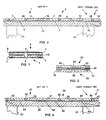
- FIGS 3 and 4 show another embodiment in cross-section of two modular panels of the First Type, folded at an attached flap type hinge on the radiation plate of each panel, the flap partially covering the plate where the plate is full to the outer edges of the boards.
- the hinged panels 31 and 36 are connected by a flange hinge 40 that is attached to the bottom of the panels on the edges of the adjacent radiation plates 34 and 39.
- the flap may be a strip of flexible plastic or fabric or a suitable strong adhering tape of negligible thickness so that when the panels 31 and 36 are unfolded as shown and laid on a sub-floor 22 supported by floor joists 21, as shown in Figure 4, there is no requirement to add compensating layers of material to the sub-floor so that the top thereof is even across the floor.
- Panel 31 consists of evenly spaced apart boards 32 and 33 and metal radiation plate or sheet 34 attached thereto by, for example staking.
- panel 36 consists of evenly spaced apart boards 37 and 38 and metal radiation plate or sheet 39 attached thereto by staking.
- Flap type hinge 40 that may be a strip of flexible plastic or fabric or a suitable strong adhering tape is attached to the bottom of the adjacent panels so that the hinged may fold as shown in Figure 3 or unfold and laid on the sub-floor as shown in Figure 4 alongside other hinged sets of panels such as 41 that consists of boards 42 and 43 and attached plate 44.
- Figure 5 shows the another embodiment in cross-section of three modular panels 51, 56 and 61 of the First Type, folded at an attached flap hinge on top of adjacent holder boards of each panel, the flap partially covering the boards.
- the hinged panels 51, 56 and 61 are connected by flange hinges 60' and 60" that are both attached to the top of the panels on the edges of the adjacent boards of the three panels.
- the flap may be a strip of flexible plastic or fabric or a suitable strong adhering tape of negligible thickness so that when the panels 51. 56 and 61 are unfolded as shown and laid on a sub-floor 22 supported by floor joists 21, as shown in Figure 6, there is no requirement to add compensating layers of material to the top of other parts of the panel boards so that the top of them is even across the floor.
- Panel 51 consists of evenly spaced apart boards 52 and 53 and metal radiation plate or sheet 54 attached thereto by, for example, staking
- panel 56 consists of evenly spaced apart boards 57 and 58 and metal radiation plate or sheet 59 attached thereto by staking
- panel 61 consists of evenly spaced apart boards 62 and 63 and metal radiation plate or sheet 64 attached thereto by staking.
- Flap type hinges 60' and 60" may be strips of flexible plastic or fabric or a suitable strong adhering tape is attached to the top of the adjacent panels so that the hinges may fold as shown in Figure 5 or unfold and laid on the sub-floor as shown in Figure 6 alongside other hinged sets of panels.
- folded panels shown in Figure 5 may not be suitable for stacking set upon set, it is suitable for nesting.
- Figure 8 shows another embodiment in cross-section of four modular panels 71, 76, 81 and 86 of the First Type, folded at attached flap hinges, that are attached alternately to the radiation plates and the boards of the four panels, the flaps fully covering the plates and/or boards.
- the hinged panels 71, 76, 81 and 86 are connected by flap hinges 80', 80" and 80"' that are attached alternately to the bottom and the top of the panels of the adjacent plates and boards of the four panels.
- the flaps may be strips of flexible plastic or fabric or a suitable strong adhering tape of negligible thickness so that when the panels 71, 76, 81 and 86 are unfolded and laid on a sub-floor 22 supported by floor joists 21, as shown in Figure 8, there is no requirement to add compensating layers of material to the top or the bottom of other parts of the panels so that the top of them and the sub-floor is even across the floor.
- Panel 71 consists of evenly spaced apart boards 72 and 73 and metal radiation plate or sheet 74 attached thereto by, for example, staking
- panel 76 consists of evenly spaced apart boards 77 and 78 and metal radiation plate or sheet 79 attached thereto by staking
- panel 81 consists of evenly spaced apart boards 82 and 83 and metal radiation plate or sheet 84 attached thereto by staking
- panel 86 consists of evenly spaced apart boards 87 and 88 and metal radiation plate or sheet 89 attached thereto by staking.
- Flap type hinges 80', 80" and 80"' may be strips of flexible plastic or fabric or a suitable strong adhering tape is attached to the top or bottom of the adjacent panels so that the hinges may fold as shown in Figure 7 or unfold and laid on the sub-floor as shown in Figure 8 alongside other hinged sets of panels.
- the folded panels of such a set is suitable for stacking set upon set.
- Figures 9 and 10 show show another embodiment in cross-section of two modular panels of the First Type, folded at an attached pin hinge (piano hinge) on top of the adjacent boards of panels of the set.
- the hinged panels 91 and 96 are connected by a pin hinge (piano hinge) 100 that is attached to the top of the adjacent boards 93 and 97 of the panels.
- the pin hinge is longitudinally rigid and preferably made of metal and is attached to the boards by staking, screwing or adhesive.
- the thickness of the hinge may or may not be negligible. If not negligible, then when the panels 91 and 96 are unfolded as shown and laid on a sub-floor 22 supported by floor joists 21, as shown in Figure 10, there may be the requirement to add compensating layers of material to the top of other parts of the panel boards so that the top is even across the floor.
- Panel 91 consists of evenly spaced apart boards 92 and 93 and metal radiation plate or sheet 94 attached thereto by, for example staking
- panel 96 consists of evenly spaced apart boards 97 and 98 and metal radiation plate or sheet 99 attached thereto by staking.
- Pin hinge 100 is attached to the top of adjacent boards 93 and 97 so that the hinged panels 91 and 96 may fold as shown in Figure 9 or unfold and laid on the sub-floor as shown in Figure 10 alongside other hinged sets of panels such as 101 that consists of boards 102 and 103 and attached plate 104.
- Figures 11 and 12 show the another embodiment herein in cross-section of two modular panels 111 and 116 of the Second Type, folded at an attached flap hinge 120 on the bottom edges of the adjacent holder boards 113 and 117 of each panel.
- panels of the Second Type consist of two spaced apart boards and a flat metal plate having a longitudinal groove the length of the plate is attached to the boards with the groove projecting into the space between the boards and the tubing is inserted into the groove in the plate between the boards.
- the tubing is in direct contact with the metal plate in the groove over most of the outer periphery of the tubing. Inserting thermally conductive filler material into the groove before the tubing is inserted is optional.
- the grooved radiation plate or sheet is preferably attached to the boards by staking as described in the above mentioned U.S. patent application serial number 08/746,458.
- the hinged panels 111 and 116 are connected by a flange hinge 120 that is attached to the edges of the bottom face of the adjacent boards 113 and 117 of the panels.
- the flap may be a strip of flexible plastic or fabric or a suitable strong adhering tape.
- the thickness of the flap is preferably negligible (less than 1,6 mm (1/16")) so that when the panels are unfolded as shown and laid on a sub-floor 22 supported by floor joists 21, as shown in Figure 12, there is no requirement to add compensating layers of material between the panels and the sub-floor.
- Panel 111 consists of evenly spaced apart boards 112 and 113 and metal radiation plate or sheet 114 attached thereto by, for example staking
- panel 116 consists of evenly spaced apart boards 117 and 118 and metal radiation plate or sheet 119 attached thereto by staking.
- Flap type hinge 100 that may be a strip of flexible plastic or fabric or a suitable strong adhering tape is attached to the bottom of adjacent boards 113 and 117 so that the hinged panels 111 and 116 may fold as shown in Figure 11 or unfold and laid on the sub-floor as shown in Figure 12 alongside other hinged sets of panels such as 121 that consists of boards 122 and 123 and attached plate 124.
- Figures 13 and 14 show another embodiment herein in cross-section of two modular panels 131 and 136 of the Second Type, folded at an attached flap hinge 140' on the bottom of the panels, fully covering the boards on the bottom of each panel.
- the hinged panels 131 and 136 are connected by a flange hinge 140' that is attached to the bottom of the panels and fully covers the entire bottom of both boards of each panel.
- the flap may be a strip of flexible plastic or fabric or a suitable strong adhering tape. The thickness of the flap need not be negligible, because it covers the entire bottom of both panels.
- the flap material may be thermally insulating and/or sound insulation as well as a hinge that allows folding the two panels as shown in Figure 13 and unfolding as shown and laid on a sub-floor 22 supported by floor joists 21, as shown in Figure 14.
- Panel 131 consists of evenly spaced apart boards 132 and 133 and metal radiation plate or sheet 134 attached thereto by, for example staking
- panel 136 consists of evenly spaced apart boards 137 and 138 and metal radiation plate or sheet 139 attached thereto by staking.
- Flap type hinge layer 140 may be thermally insulating and/or sound insulation as well as a hinge that allows folding the two panels to fold as shown in Figure and unfold and laid on the sub-floor as shown in Figure 14 alongside other hinged sets of panels such as 141 that consists of boards 142 and 143 and attached plate 144.
- Figures 15 and 16 show another embodiment herein in cross-section of two modular panels 151 and 156 of the Second Type, folded at an attached flap hinge 160' on the bottom of the panels, fully covering the boards on the bottom of each panel.
- Both edges of each panel are contoured with matching contours.
- the matching contours are simple bevels and serve to provide an overlap of the panels in a set when they are unfolded.
- the outside edges of each panel are also contoured so that each set edge overlaps the set it is adjacent to.
- the hinged panels 151 and 156 are connected by a flange hinge 160' that is attached to the bottom of the panels and fully covers the entire bottom of both boards of each panel.
- the flap may be a strip of flexible plastic or fabric or a suitable strong adhering tape. The thickness of the flap need not be negligible, because it covers the entire bottom of both panels.
- the flap material may be thermally insulating and/or sound insulation as well as a hinge that allows folding the two panels as shown in Figure 15 and unfolding as shown and laid on a sub-floor 22 supported by floor joists 21, as shown in Figure 16.
- Panel 151 consists of evenly spaced apart boards 152 and 153 and metal radiation plate or sheet 154 attached thereto by, for example staking
- panel 156 consists of evenly spaced apart boards 157 and 158 and metal radiation plate or sheet 159 attached thereto by staking.
- Flap type hinge layer 160' may be thermally insulating and/or sound insulation as well as a hinge that allows folding the two panels to fold as shown in Figure 15 and unfold and laid on the sub-floor as shown in Figure 16 alongside other hinged sets of panels such as 161 that consists of boards 162 and 63 and attached plate 164.
- the outside edges of all boards are contoured with matching contours.
- the matching contours are simple bevels and serve to provide an overlap of the panels in a set when they are unfolded.
- the outside edges of each panel are also contoured so that each set edge overlaps the set it is adjacent to.
- the contour could also be matching steps.
- the outside edges of all panel boards could be stepped to fit together when unfolded and to fit side by side with an adjacent set at installation on the sub-floor.
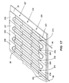
- a typical wood frame construction sub-floor is shown in Figure 17. It includes a sub-floor 22 of plywood, particle board or one inch boards on floor joists.
- the installation of the unfolded side by side hinged sets of modular panels of the First Type and additional kinds (U turn modular panels), also of the First Type, and tubing 20 is all on top of the sub-floor.
- the three sets of eight are unfolded and laid on the floor interlocking with each other as shown, along with seven U turn modular panels 215 through 222 that have accommodating staggered edges that fit the staggered panels of sets 227 and 225.
- the interlocking sets 225 to 227 together with the seven U turn modular panels 215 to 222 provide for eight courses of the tubing 20 to be inserted into the aligned panels.
- Separate straight panel sections 222 and 223 provide the tubing entry and exit to the eight courses.
- the modular panels in this installation hold tubing 20 as a continuous length laid down serpentine fashion from panel to panel, embedded in the holding spaces of the straight and U turn modular panels and held securely therein by the space structure itself and the filler material therein.
- the radiating plates do not show as they are on the bottom face of the panels.
- the flap hinges such as 80', 80" and 80" shown in Figure 8 are not shown in Figure 17, but as described connect the adjacent panels of each set together and permit each set to be stored folded in a stack that is eight panels thickness high.
- a typical wood frame construction wall structure is shown in Figure 18. It includes a wall sole plate 240, studs 241 to 249 and top plate 250 with two sets 262 and 263 of staggered, side-by-side hinged panels, each of seven straight run modular panels of the Second Type and additional kinds (U turn modular panels), also of the Second Type, and tubing 20 is all on mounted on the wall studs.
- the two sets of seven are unfolded and attached to the stud, and/or to stud widening boards 270, 171 and 272, interlocking with each other as shown, along with six U turn modular panels 254 through 259 that have accommodating staggered edges that fit the staggered panels of sets 262 and 263.
- the interlocking sets 262 to 263 together with the six U turn modular panels 254 through 259 provide for seven courses of the tubing 20 to be inserted into the aligned panels.
- Separate straight panel sections 260 and 261 provide the tubing entry and exit to the eight courses.
- the modular panels in this installation hold tubing 20 as a continuous length laid down serpentine fashion from panel to panel, embedded in the holding spaces of the straight and U turn modular panels and held securely therein by the space structure itself of such Second Type panels.
- the radiating plates are on top and they do show.
- the flap hinges such as 120 shown in Figure 12 are not shown in Figure 18, but as described connect the adjacent panels of each set together and permit each set to be stored folded in a stack that is seven panels thickness high.
- Radiant hydronic cooling described herein is effective when installed in the ceiling, because the cooled air against the ceiling falls to the floor creating a convection flow that is favorable to providing even cooling throughout the room.
- the ceiling of a room before the finished ceiling is installed is bare rafters, joists or strapping.
- Such a ceiling installation would be essentially the same as the wall installation shown in Figure 24, except it would be on the rafters, joists, etc. of the ceiling instead of the wall studs as in Figure 18.
- Radiant hydronic cooling described herein is effective when installed in the ceiling, because the cooled air against the ceiling falls to the floor creating a convection flow that is favorable to providing even cooling throughout the room.
- the ceiling of a room before the finished ceiling is installed is bare rafters, joists or strapping.
- Such a ceiling installation would be essentially the same as the wall installation shown in Figure 18, except it would be on the rafters, joists, etc. of the ceiling instead of the wall studs.
- a compliant filler material around the tubing held in the tubing holding space in any of the embodiments herein is applied to the space before the tubing is inserted or forced into the space.
- a purpose of the filler material is to hold the tubing in the space as an adhesive, while at the same time allowing the tubing to expand and contract longitudinally within the space of successive modular pieces that hold a length of tubing at installation. The tubing must be free to expand and contract, while the modular pieces are fixed by staples, nails, screws, etc. to the sub-floor, wall studs or ceiling rafters.
- Another purpose of the filler material is to reduce noise created by expansions and contractions of the tubing in the space.
- Yet another and important purpose is to provide a medium of thermal conduction from the tubing to the plate.
- a suitable filler material for any of these purposes is silicone rubber.
- a convenient form of silicone rubber that can be used in the installations described herein is available commercially as a sealant or a caulking in viscous liquid form, usually dispensed from a tube by simply forcing it out of a nozzle on the tube.
- a sealant/caulking is usually a prepared mix of silicone dioxide, methanol and ammonia.
- a commercial source of this sealant/caulking mix is a General Electric product called SILICONE II that remains resilient for many years after it is applied.
Landscapes
- Engineering & Computer Science (AREA)
- Physics & Mathematics (AREA)
- Thermal Sciences (AREA)
- Chemical & Material Sciences (AREA)
- Combustion & Propulsion (AREA)
- Mechanical Engineering (AREA)
- General Engineering & Computer Science (AREA)
- Floor Finish (AREA)
- Steam Or Hot-Water Central Heating Systems (AREA)
- Building Environments (AREA)
Claims (17)
- Wasserstrahlungsheiz- und/oder -kühlsystem mit einer Heiz/Kühlschleife aus einem wasserführenden Leitungsstrang (20), montierbar in einem Fußboden, einer Wand oder einer Decke eines durch dieses System geheizten/gekühlten Raums, wobei das System Modulpaneele (1,6) jeweils aus einer Metallplatte oder -folie (4) auf einem Brett oder Brettern (3,7) aufweist, die einen Rohrhalteraum darbieten, in den der Rohrstrang (20) eingesetzt und an der Platte (4) in innigem Wärmekontakt mit dieser gehalten ist, so daß die Platte (4) durch Wärmeleitung zwischen dem Wasser im Rohrstrang (20) und der Platte (4) geheizt/gekühlt wird, dadurch gekennzeichnet, daß(a) zwei oder mehrere Paneele (1,6) zur Bildung eines Gelenksatzes von Paneelen gelenkig miteinander verbunden sind,(b) die Paneele (1,6) entlang ihren Seiten in einem regelmäßigen Versatzverhältnis gelenkig miteinander verbunden sind,(c) wodurch zwei oder mehrere der Sätze gelenkig miteinander verbundener Paneele (1,6), auseinandergeklappt an ihren Scharnieren (10) und endseitig aneinandergrenzend auf einem Fußboden, an einer Wand oder einer Decke angeordnet, eng miteinander zusammengeschlossen sind und fluchtende langgestreckte Rohrhalteräume bilden, in die der Rohrstrang eingesetzt und an der Strahlungsplatte (4) gehalten ist, und darauf eine Abdeckung eines Fertigbodens, einer Wand oder einer Decke installiert werden kann und das System zum Heizen oder Kühlen des Raums betrieben wird.
- Wasserstrahlungsheiz- und/oder -kühlsystem nach Anspruch 1, bei dem (a) das Scharnier (10) ein Streifen flexiblen Materials ist, der an den benachbarten Brettern (3,7) der Paneele (1,6) in dem Satz angebracht ist.
- Wasserstrahlungsheiz- und/oder -kühlsystem nach Anspruch 1, bei dem (a) das Scharnier (10) ein Streifen flexiblen Materials ist, der an den Platten (4) der Paneele (1,6) in dem Satz angebracht ist.
- Wasserstrahlungsheiz- und/oder -kühlsystem nach Anspruch 2, bei dem (a) der Streifen flexiblen Materials auf der Oberseite der benachbarten Bretter (3,7) angebracht ist.
- Wasserstrahlungsheiz- und/oder -kühlsystem nach Anspruch 2, bei dem (a) der Streifen flexiblen Materials an der Unterseite der benachbarten Bretter (3,7) angebracht ist.
- Wasserstrahlungsheiz- und/oder -kühlsystem nach Anspruch 3, bei dem (a) der Streifen flexiblen Materials an den Platten (4) auf der Oberseite der Paneele (1,6) in dem Satz angebracht ist.
- Wasserstrahlungsheiz- und/oder -kühlsystem nach Anspruch 3, bei dem (a) der Streifen flexiblen Materials an den Platten (4) auf der Unterseite der Paneele (1,6) in dem Satz angebracht ist.
- Wasserstrahlungsheiz- und/oder -kühlsystem nach Anspruch 1, bei dem (a) das Scharnier (140) ein Streifen flexiblen Materials ist, der die gesamte Unterseite beider Paneele (131,136) des Satzes bedeckt.
- Wasserstrahlungsheiz- und/oder -kühlsystem nach Anspruch 8, bei dem (a) der Streifen (140') flexiblen Materials ferner eine Wärmeisolierschicht bildet.
- Wasserstrahlungsheiz- und/oder -kühlsystem nach Anspruch 1, bei dem (a) das Modulpaneel aus zwei gleichmäßig beabstandeten Brettern (7,9) und einer ebenen Metallplatte oder -folie (4) besteht, die an den Brettern über dem den Rohrhalteraum bildenden Raum hinweg angebracht ist, der durch den Raum zwischen den Brettern (7,9) und dem sich über den Raum erstreckenden Teil der Platte definiert ist.
- Wasserstrahlungsheiz- und/oder -kühlsystem nach Anspruch 10, bei dem (a) das Scharnier (120) ein Streifen flexiblen Materials ist, der an den benachbarten Rändern der Paneele in dem Satz angebracht ist.
- Wasserstrahlungsheiz- und/oder -kühlsystem nach Anspruch 1, bei dem (a) das Modulpaneel aus zwei voneinander beabstandeten Brettern (112) und einer Metallplatte oder -folie (114) besteht, die eine gleichförmige Längsnut aufweist, welche der Länge nach an den Brettern angebracht ist, wobei die Nut in den Raum zwischen den Brettern (112) vorspringt.
- Wasserstrahlungsheiz- und/oder -kühlsystem nach Anspruch 12, bei dem (a) das Scharnier ein Streifen (120) flexiblen Materials ist, der an den benachbarten Brettern (112) der Paneele in dem Satz angebracht ist.
- Wasserstrahlungsheiz- und/oder -kühlsystem nach Anspruch 12, bei dem (a) die Paneele (111) in dem Satz Seite an Seite gelenkig miteinander verbunden sind.
- Wasserstrahlungsheiz- und/oder -kühlsystem nach Anspruch 12, bei dem (a) die Paneele (111) in dem Satz endseitig gelenkig miteinander verbunden sind.
- Wasserstrahlungsheiz- und/oder -kühlsystem nach Anspruch 1, bei dem (a) das Scharnier (100) eine Stange aufweist, die zwei an den Paneelen in dem Satz angebrachte Teile miteinander verbindet.
- Verfahren zum Herstellen eines Wasserstrahlungsheiz- und/oder -kühlsystems mit einer Heiz/Kühlschlange aus einem wasserführenden Rohrstrang (20), montierbar in einem Fußboden, einer Wand oder einer Decke eines durch das System geheizten/gekühlten Raums, wobei das System Modulpaneele (1,6) jeweils aus einer Metallplatte oder -folie (4) auf einem Brett oder Brettern (3,7) aufweist, die einen langgestreckten Rohrhalteraum bilden, in dem der Rohrstrang (20) eingesetzt und an der Platte (4) in innigem Wärmekontakt mit dieser gehalten ist, so daß die Platte (4) durch Wärmeleitung zwischen dem Wasser im Rohrstrang (20) und der Platte (4) geheizt/gekühlt wird, gekennzeichnet durch die Schritte, daß(a) zwei oder mehrere Sätze der gelenkig miteinander verbundenen Paneele (1,6) zur Bildung von zwei oder mehreren Gelenksätzen von Paneelen bereitgestellt werden,(b) die Paneele (1,6) jedes Satzes entlang ihren Seiten in einem regelmäßigen Versatzverhältnis gelenkig miteinander verbunden sind,(c) die beiden oder mehreren Sätze gelenkig miteinander verbundener Paneele (1,6) an ihren Scharnieren (10) auseinandergeklappt und die auseinandergeklappten Sätze Ende an Ende auf einem Fußboden, einer Wand oder einer Decke angebracht werden und(d) die auseinandergeklappten Sätze, die Ende an Ende liegen, unter gegenseitigem Aneinanderstoßen eng zusammengeschlossen werden, wodurch(e) die langgestreckten Rohrhalteräume der Paneele der Sätze, in die der Rohrstrang einzusetzen ist, untereinander ausgerichtet sind.
Applications Claiming Priority (3)
| Application Number | Priority Date | Filing Date | Title |
|---|---|---|---|
| US340369 | 1982-01-18 | ||
| US09/340,369 US6182903B1 (en) | 1999-05-07 | 1999-06-28 | Radiant floor wall and ceiling hydronic heating and/or cooling systems, using modular panels hinged together in sets of panels, staggering the positions of panels in the sets so that sets are interlocking |
| PCT/US2000/017804 WO2001006180A2 (en) | 1999-06-28 | 2000-06-28 | A modular radiant floor heating or cooling system |
Publications (3)
| Publication Number | Publication Date |
|---|---|
| EP1159568A2 EP1159568A2 (de) | 2001-12-05 |
| EP1159568A4 EP1159568A4 (de) | 2004-12-01 |
| EP1159568B1 true EP1159568B1 (de) | 2005-12-14 |
Family
ID=23333070
Family Applications (1)
| Application Number | Title | Priority Date | Filing Date |
|---|---|---|---|
| EP00946883A Expired - Lifetime EP1159568B1 (de) | 1999-06-28 | 2000-06-28 | Boden-, wand- und deckenheiz- oder kühlanlage |
Country Status (6)
| Country | Link |
|---|---|
| US (1) | US6182903B1 (de) |
| EP (1) | EP1159568B1 (de) |
| AT (1) | ATE313045T1 (de) |
| CA (1) | CA2354564C (de) |
| DE (1) | DE60024789T2 (de) |
| WO (1) | WO2001006180A2 (de) |
Families Citing this family (28)
| Publication number | Priority date | Publication date | Assignee | Title |
|---|---|---|---|---|
| US8382004B2 (en) * | 2001-04-04 | 2013-02-26 | Graftech International Holdings Inc. | Flexible graphite flooring heat spreader |
| US6926077B2 (en) * | 2001-11-27 | 2005-08-09 | Mitsubishi Chemical Functional Products, Inc. | Foldable heat radiating sheet |
| US7377079B2 (en) * | 2002-08-14 | 2008-05-27 | W. Lehbrink Gmbh & Co. Kg, Maschinenfabrik | Flexibly connected panel elements |
| US8028742B2 (en) * | 2005-01-05 | 2011-10-04 | Joachim Fiedrich | Radiant heating/cooling tubing substrate with in plane bus |
| WO2007033255A2 (en) * | 2005-09-14 | 2007-03-22 | Uponor, Inc. | Radiant heating system and method |
| USD541396S1 (en) | 2005-10-21 | 2007-04-24 | Createc Corporation | Radiant heat floor panel |
| US8020783B2 (en) * | 2006-07-19 | 2011-09-20 | Backman Jr James Joseph | Radiant mat grid |
| US7628150B2 (en) * | 2007-08-17 | 2009-12-08 | Vladimir Malkov | Versatile flexible mat and method of implementing and using same |
| USD587358S1 (en) | 2007-09-07 | 2009-02-24 | Createc Corporation | Radiant floor panel |
| EP2129191A1 (de) * | 2008-05-30 | 2009-12-02 | Electrolux Home Products Corporation N.V. | Subsystemanordnung für Induktion |
| US8288689B1 (en) | 2008-09-02 | 2012-10-16 | Adelman Dean W | Radiant heating and cooling panel |
| KR100915499B1 (ko) * | 2008-12-16 | 2009-09-03 | 천열에너지 주식회사 | 난방패널의 생산방법 |
| EP2395882B1 (de) * | 2009-02-13 | 2013-07-03 | Koninklijke Philips Electronics N.V. | Bodenkonstruktion mit variablem elastizitätsgrad |
| US20100237157A1 (en) * | 2009-03-21 | 2010-09-23 | Zhaojun Guo | Ground heating flooring with internal heating conduction structure |
| CN201411875Y (zh) * | 2009-06-11 | 2010-02-24 | 李新发 | 具有传热功能的龙骨 |
| US9885173B2 (en) | 2012-12-31 | 2018-02-06 | Mark Hauenstein | Multiple layered radiant active assembly |
| US9995538B2 (en) | 2013-01-09 | 2018-06-12 | Carrier Corporation | Cleat arrangement for accessory installation to a heating or cooling system component |
| US9816709B2 (en) | 2013-02-27 | 2017-11-14 | Gray Metal Products, Inc. | Retaining panel for radiant thermal transfer and method |
| US9146038B2 (en) * | 2013-06-12 | 2015-09-29 | Codi Group, Llc | Impact and/or sound deadening hydronic sub-flooring panel and related system and method |
| JP2016223657A (ja) * | 2015-05-28 | 2016-12-28 | 株式会社トヨックス | 輻射パネル |
| WO2017106860A1 (en) | 2015-12-17 | 2017-06-22 | Pentair Thermal Management Llc | Floor underlayment for retaining heater cable |
| US20180298611A1 (en) * | 2017-04-17 | 2018-10-18 | David R. Hall | Configurable Hydronic Structural Panel |
| US20200149288A1 (en) | 2018-11-13 | 2020-05-14 | Katerra Inc. | Floor panel |
| US12013149B2 (en) * | 2019-04-15 | 2024-06-18 | Ut-Battelle, Llc | Thermally anisotropic composites for thermal management in building environments |
| DE202023100456U1 (de) | 2023-01-31 | 2024-05-07 | REHAU Industries SE & Co. KG | Heiz- und/oder Kühldecke sowie Wärmeleitlamellenanordnung dafür |
| DE202023105216U1 (de) * | 2023-09-11 | 2025-01-15 | REHAU Industries SE & Co. KG | Heiz- und/oder Kühldecke sowie Wärmeleitlamellenanordnung dafür |
| DE202023105219U1 (de) * | 2023-09-11 | 2024-12-13 | REHAU Industries SE & Co. KG | Heiz- und/oder Kühldecke sowie Wärmeleitlamellenanordnung dafür |
| DE202023106685U1 (de) * | 2023-11-14 | 2025-02-18 | REHAU Industries SE & Co. KG | Heiz- und/oder Kühldecke sowie Wärmeleitlamellenanordnung dafür |
Family Cites Families (6)
| Publication number | Priority date | Publication date | Assignee | Title |
|---|---|---|---|---|
| SE8902324L (sv) * | 1989-06-27 | 1990-12-28 | Bengt Valdemar Eggemar | Foerfarande och anordning vid vaermevaexling |
| US5131458A (en) * | 1991-03-25 | 1992-07-21 | Davis Energy Group, Inc. | Modular back side radiant heating panels with spring retention devices |
| US5292065A (en) * | 1992-06-30 | 1994-03-08 | Joachim Fiedrich | Radiant floor and wall hydronic heating systems |
| US5454428A (en) * | 1993-11-22 | 1995-10-03 | Radiant Engineering, Inc. | Hydronic radiant heat distribution panel and system |
| US5788152A (en) * | 1995-03-15 | 1998-08-04 | Alsberg; Terry Wayne W. | Floor heating system |
| CH692094A5 (de) * | 1995-09-23 | 2002-01-31 | Barcol Air | Kontaktelement und Deckenelement für eine Heiz- und Kühldecke. |
-
1999
- 1999-06-28 US US09/340,369 patent/US6182903B1/en not_active Expired - Lifetime
-
2000
- 2000-06-28 EP EP00946883A patent/EP1159568B1/de not_active Expired - Lifetime
- 2000-06-28 CA CA002354564A patent/CA2354564C/en not_active Expired - Lifetime
- 2000-06-28 DE DE60024789T patent/DE60024789T2/de not_active Expired - Lifetime
- 2000-06-28 AT AT00946883T patent/ATE313045T1/de not_active IP Right Cessation
- 2000-06-28 WO PCT/US2000/017804 patent/WO2001006180A2/en not_active Ceased
Also Published As
| Publication number | Publication date |
|---|---|
| EP1159568A2 (de) | 2001-12-05 |
| US6182903B1 (en) | 2001-02-06 |
| WO2001006180A2 (en) | 2001-01-25 |
| EP1159568A4 (de) | 2004-12-01 |
| CA2354564A1 (en) | 2001-01-25 |
| DE60024789D1 (de) | 2006-01-19 |
| DE60024789T2 (de) | 2006-09-07 |
| WO2001006180A3 (en) | 2001-07-26 |
| CA2354564C (en) | 2007-02-13 |
| ATE313045T1 (de) | 2005-12-15 |
Similar Documents
| Publication | Publication Date | Title |
|---|---|---|
| EP1159568B1 (de) | Boden-, wand- und deckenheiz- oder kühlanlage | |
| EP1161642B1 (de) | Boden-, wand- und deckenheiz- oder kühlanlage | |
| US5931381A (en) | For radiant floor, wall and ceiling hydronic heating and/or cooling systems using metal plates that are heated or cooled by attached tubing that is fed hot or cold water, techniques of improving performance and avoiding condensation when cooling | |
| US6330980B1 (en) | Dry installation of a radiant floor or wall hydronic heating system, metal radiating plates that attach to the edges of side-by-side boards and provide metal slots for holding hot water tubing | |
| US20040026525A1 (en) | In radiant wall and ceiling hydronic room heating or cooling systems, using tubing that is fed hot or cold water, the tubing is embedded in gypsum or cement wallboard in intimate thermal contact therewith so that the wallboard heats or cools the room | |
| FI106406B (fi) | Moduuli käytettäväksi lattialämmitys-/jäähdytysjärjestelmässä, menetelmä lattialämmitys-/jäähdytysjärjestelmän asentamiseksi ja lattialämmitys-/jäähdytysjärjestelmä | |
| US5788152A (en) | Floor heating system | |
| US20090014152A1 (en) | Hydronic floor heating system with adaptive fluid circuit | |
| US8028742B2 (en) | Radiant heating/cooling tubing substrate with in plane bus | |
| US20040040693A1 (en) | In a dry installation of a radiant floor or wall hydronic heating system, metal radiating sheets that attach to the rough floor or wall adapted with a metal slot for holding hot water tubing | |
| CA2185548C (en) | Floor heating system | |
| US20090314848A1 (en) | Radiant Heating System and Method | |
| US8650832B2 (en) | In-wall hydronic thermal control system and installation method | |
| CA2375641C (en) | Assembly and method of radiant/structural floor system | |
| LT3350B (en) | Radiant or radiant-ventilating airconditioning prefabricated elements and air conditioning installation including said elements | |
| PL198906B1 (pl) | Element podłogowy do wytwarzania pustych komór wewnątrz podłóg dla rur grzejnych i chłodzących oraz płyta złączna dla elementów podłogowych | |
| CA2274410A1 (en) | In radiant floor, wall and celling hydronic cooling systems and heating and cooling systems, using metal plates that are heated or cooled by attached tubing that is fed hot or cold water, structures of plates and tubing attachments | |
| JP2000121167A (ja) | 蓄熱パネル及び蓄熱式空調システム | |
| KR100847798B1 (ko) | 난방용 패널의 시공방법 | |
| JP4115614B2 (ja) | 床暖房パネル及びその敷設方法 | |
| JP2535763Y2 (ja) | 住宅用内装パネル | |
| EP0999415A2 (de) | Heizungspaneele für Fussbodenheizung | |
| EP3524892B1 (de) | Wärmeübertragungsplatte und -system für fussbodenheizung | |
| EP0943873A1 (de) | Gerät und Verfahren zur Befestigung einer Strahlungsplatte an Halterungen einer Moduleinheit einer Boden- oder Wandheizungsanlage | |
| JP3594454B2 (ja) | 床暖房装置の上敷式木質床暖房パネル |
Legal Events
| Date | Code | Title | Description |
|---|---|---|---|
| PUAI | Public reference made under article 153(3) epc to a published international application that has entered the european phase |
Free format text: ORIGINAL CODE: 0009012 |
|
| AK | Designated contracting states |
Kind code of ref document: A2 Designated state(s): AT BE CH CY DE DK ES FI FR GB GR IE IT LI LU MC NL PT SE |
|
| 17P | Request for examination filed |
Effective date: 20020128 |
|
| A4 | Supplementary search report drawn up and despatched |
Effective date: 20041019 |
|
| RIC1 | Information provided on ipc code assigned before grant |
Ipc: 7F 24D 3/16 B Ipc: 7F 24D 5/10 A |
|
| GRAP | Despatch of communication of intention to grant a patent |
Free format text: ORIGINAL CODE: EPIDOSNIGR1 |
|
| GRAS | Grant fee paid |
Free format text: ORIGINAL CODE: EPIDOSNIGR3 |
|
| GRAA | (expected) grant |
Free format text: ORIGINAL CODE: 0009210 |
|
| AK | Designated contracting states |
Kind code of ref document: B1 Designated state(s): AT BE CH CY DE DK ES FI FR GB GR IE IT LI LU MC NL PT SE |
|
| PG25 | Lapsed in a contracting state [announced via postgrant information from national office to epo] |
Ref country code: IT Free format text: LAPSE BECAUSE OF FAILURE TO SUBMIT A TRANSLATION OF THE DESCRIPTION OR TO PAY THE FEE WITHIN THE PRESCRIBED TIME-LIMIT;WARNING: LAPSES OF ITALIAN PATENTS WITH EFFECTIVE DATE BEFORE 2007 MAY HAVE OCCURRED AT ANY TIME BEFORE 2007. THE CORRECT EFFECTIVE DATE MAY BE DIFFERENT FROM THE ONE RECORDED. Effective date: 20051214 Ref country code: NL Free format text: LAPSE BECAUSE OF FAILURE TO SUBMIT A TRANSLATION OF THE DESCRIPTION OR TO PAY THE FEE WITHIN THE PRESCRIBED TIME-LIMIT Effective date: 20051214 Ref country code: BE Free format text: LAPSE BECAUSE OF FAILURE TO SUBMIT A TRANSLATION OF THE DESCRIPTION OR TO PAY THE FEE WITHIN THE PRESCRIBED TIME-LIMIT Effective date: 20051214 Ref country code: AT Free format text: LAPSE BECAUSE OF FAILURE TO SUBMIT A TRANSLATION OF THE DESCRIPTION OR TO PAY THE FEE WITHIN THE PRESCRIBED TIME-LIMIT Effective date: 20051214 Ref country code: LI Free format text: LAPSE BECAUSE OF FAILURE TO SUBMIT A TRANSLATION OF THE DESCRIPTION OR TO PAY THE FEE WITHIN THE PRESCRIBED TIME-LIMIT Effective date: 20051214 Ref country code: FI Free format text: LAPSE BECAUSE OF FAILURE TO SUBMIT A TRANSLATION OF THE DESCRIPTION OR TO PAY THE FEE WITHIN THE PRESCRIBED TIME-LIMIT Effective date: 20051214 Ref country code: CH Free format text: LAPSE BECAUSE OF FAILURE TO SUBMIT A TRANSLATION OF THE DESCRIPTION OR TO PAY THE FEE WITHIN THE PRESCRIBED TIME-LIMIT Effective date: 20051214 |
|
| REG | Reference to a national code |
Ref country code: GB Ref legal event code: FG4D |
|
| REG | Reference to a national code |
Ref country code: CH Ref legal event code: EP |
|
| REG | Reference to a national code |
Ref country code: IE Ref legal event code: FG4D |
|
| REF | Corresponds to: |
Ref document number: 60024789 Country of ref document: DE Date of ref document: 20060119 Kind code of ref document: P |
|
| PG25 | Lapsed in a contracting state [announced via postgrant information from national office to epo] |
Ref country code: GR Free format text: LAPSE BECAUSE OF FAILURE TO SUBMIT A TRANSLATION OF THE DESCRIPTION OR TO PAY THE FEE WITHIN THE PRESCRIBED TIME-LIMIT Effective date: 20060314 Ref country code: DK Free format text: LAPSE BECAUSE OF FAILURE TO SUBMIT A TRANSLATION OF THE DESCRIPTION OR TO PAY THE FEE WITHIN THE PRESCRIBED TIME-LIMIT Effective date: 20060314 |
|
| PG25 | Lapsed in a contracting state [announced via postgrant information from national office to epo] |
Ref country code: ES Free format text: LAPSE BECAUSE OF FAILURE TO SUBMIT A TRANSLATION OF THE DESCRIPTION OR TO PAY THE FEE WITHIN THE PRESCRIBED TIME-LIMIT Effective date: 20060325 |
|
| REG | Reference to a national code |
Ref country code: SE Ref legal event code: TRGR |
|
| PG25 | Lapsed in a contracting state [announced via postgrant information from national office to epo] |
Ref country code: PT Free format text: LAPSE BECAUSE OF FAILURE TO SUBMIT A TRANSLATION OF THE DESCRIPTION OR TO PAY THE FEE WITHIN THE PRESCRIBED TIME-LIMIT Effective date: 20060515 |
|
| NLV1 | Nl: lapsed or annulled due to failure to fulfill the requirements of art. 29p and 29m of the patents act | ||
| PG25 | Lapsed in a contracting state [announced via postgrant information from national office to epo] |
Ref country code: MC Free format text: LAPSE BECAUSE OF NON-PAYMENT OF DUE FEES Effective date: 20060630 |
|
| REG | Reference to a national code |
Ref country code: CH Ref legal event code: PL |
|
| PLBE | No opposition filed within time limit |
Free format text: ORIGINAL CODE: 0009261 |
|
| STAA | Information on the status of an ep patent application or granted ep patent |
Free format text: STATUS: NO OPPOSITION FILED WITHIN TIME LIMIT |
|
| 26N | No opposition filed |
Effective date: 20060915 |
|
| EN | Fr: translation not filed | ||
| PG25 | Lapsed in a contracting state [announced via postgrant information from national office to epo] |
Ref country code: FR Free format text: LAPSE BECAUSE OF FAILURE TO SUBMIT A TRANSLATION OF THE DESCRIPTION OR TO PAY THE FEE WITHIN THE PRESCRIBED TIME-LIMIT Effective date: 20070202 |
|
| PG25 | Lapsed in a contracting state [announced via postgrant information from national office to epo] |
Ref country code: LU Free format text: LAPSE BECAUSE OF NON-PAYMENT OF DUE FEES Effective date: 20060628 |
|
| PG25 | Lapsed in a contracting state [announced via postgrant information from national office to epo] |
Ref country code: CY Free format text: LAPSE BECAUSE OF FAILURE TO SUBMIT A TRANSLATION OF THE DESCRIPTION OR TO PAY THE FEE WITHIN THE PRESCRIBED TIME-LIMIT Effective date: 20051214 Ref country code: FR Free format text: LAPSE BECAUSE OF FAILURE TO SUBMIT A TRANSLATION OF THE DESCRIPTION OR TO PAY THE FEE WITHIN THE PRESCRIBED TIME-LIMIT Effective date: 20051214 |
|
| PGFP | Annual fee paid to national office [announced via postgrant information from national office to epo] |
Ref country code: SE Payment date: 20080630 Year of fee payment: 9 |
|
| PG25 | Lapsed in a contracting state [announced via postgrant information from national office to epo] |
Ref country code: SE Free format text: LAPSE BECAUSE OF NON-PAYMENT OF DUE FEES Effective date: 20090629 |
|
| PGFP | Annual fee paid to national office [announced via postgrant information from national office to epo] |
Ref country code: DE Payment date: 20120522 Year of fee payment: 13 Ref country code: IE Payment date: 20120614 Year of fee payment: 13 |
|
| PGFP | Annual fee paid to national office [announced via postgrant information from national office to epo] |
Ref country code: GB Payment date: 20120516 Year of fee payment: 13 |
|
| GBPC | Gb: european patent ceased through non-payment of renewal fee |
Effective date: 20130628 |
|
| REG | Reference to a national code |
Ref country code: IE Ref legal event code: MM4A |
|
| REG | Reference to a national code |
Ref country code: DE Ref legal event code: R119 Ref document number: 60024789 Country of ref document: DE Effective date: 20140101 |
|
| PG25 | Lapsed in a contracting state [announced via postgrant information from national office to epo] |
Ref country code: IE Free format text: LAPSE BECAUSE OF NON-PAYMENT OF DUE FEES Effective date: 20130628 Ref country code: GB Free format text: LAPSE BECAUSE OF NON-PAYMENT OF DUE FEES Effective date: 20130628 Ref country code: DE Free format text: LAPSE BECAUSE OF NON-PAYMENT OF DUE FEES Effective date: 20140101 |