EP1159909A1 - Duschkabine - Google Patents
Duschkabine Download PDFInfo
- Publication number
- EP1159909A1 EP1159909A1 EP01401403A EP01401403A EP1159909A1 EP 1159909 A1 EP1159909 A1 EP 1159909A1 EP 01401403 A EP01401403 A EP 01401403A EP 01401403 A EP01401403 A EP 01401403A EP 1159909 A1 EP1159909 A1 EP 1159909A1
- Authority
- EP
- European Patent Office
- Prior art keywords
- shower
- cabin
- wall
- receiver
- panel
- Prior art date
- Legal status (The legal status is an assumption and is not a legal conclusion. Google has not performed a legal analysis and makes no representation as to the accuracy of the status listed.)
- Withdrawn
Links
Images


Classifications
-
- A—HUMAN NECESSITIES
- A47—FURNITURE; DOMESTIC ARTICLES OR APPLIANCES; COFFEE MILLS; SPICE MILLS; SUCTION CLEANERS IN GENERAL
- A47K—SANITARY EQUIPMENT; ACCESSORIES THEREFOR, e.g. TOILET ACCESSORIES
- A47K3/00—Baths; Showers; Appurtenances therefor
- A47K3/28—Showers or bathing douches
- A47K3/283—Fixed showers
- A47K3/284—Pre-fabricated shower cabinets
Definitions
- the present invention relates to a shower cubicle, and aims in particular such a cabin capable of receiving not only standard taps but also various equipment, for example a hydrotherapy massage system.
- a usual drawback of existing shower stalls is to require, for their maintenance, disassembly often causing deterioration of the cabin environment (tiling, furniture) to allow access to the various equipment of this cabin, in particular of the taps.
- the object of the invention is precisely to propose a shower cabin which allows convenient and economical servicing and maintenance, and allows in particular access to organs and equipment to be repaired or replaced without it be necessary to deteriorate the cabin environment.
- Another object of the invention consists in proposing a shower cabin which, in the case of complex equipment in particular, authorizes the adjustment thereof without the user having to enter the cabin.
- the invention provides a shower enclosure comprising: a receiver or tray intended to receive the water from the shower and connected to a drain of this water; and surrounding this receiver, a bottom wall carrying the cabin equipment as well a shower wall comprising or constituting the entrance door to this cabin, characterized in that it comprises at least one strip receiving one or more showers, the strip being arranged on the bottom wall and removable from the inside from the cabin.
- the bottom wall and the shower wall each constitute a autonomous element, these elements being equipped with mutual assembly means as well as means of connection with the receiver.
- the assembly means are accessible from outside the assembled cabin and, from preferably allow disassembly of the shower wall from the bottom wall by access to the assembly means from the side corresponding to the wall of shower.
- the bottom wall consists of a central panel or corner panel which is flanked by two side panels and is permanently attached thereto, the strip being arranged on one of the panels lateral.
- the central panel or corner panel be fixed to the two side panels permanently but removable from preferably from inside the assembled cabin. Thanks to this arrangement, it is possible, if necessary, to disassemble the walls from one another without having to move the shower tray without damaging the cabin environment.
- the side panel on which the strip (42) is arranged can present a niche receiving the banner.
- Another banner receiving one or more showers can be advantageously arranged on the other side panels.
- the receiver presents on a part at least from its upper edge a rib, while a groove of the part bottom of a cross member is capable of covering said rib, this cross member constituting the lower edge of the shower screen.
- the crosspiece is joined by a end to one face of a post fixed along a rim of the side panel adjacent, by means of screws accessible from outside the cabin.
- one or more pieces of equipment the cabin are adapted to be controlled remotely by means of a remote control, preferably of the infrared type.
- a remote control preferably of the infrared type.
- This preferred embodiment can also be implemented independently on shower enclosures that do not have some or all of the features of the invention mentioned above. It is particularly advantageous that the remote control makes it possible to control this or these equipment (s) from outside the assembled shower enclosure.
- Figure 9 is a sectional view showing the assembly of the side panel on the receiver.
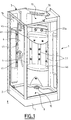
- the shower cabin 1 comprises: at its base a receiver or tray 2 forming a base; a wall of bottom 3 (see Figure 4) consisting of several panels as we will see better below, and on which the cabin equipment is fixed; and a wall of shower 4 usually allowing access to the cabin.
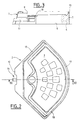
- Receiver 2 an embodiment of which is shown in detail in Figures 2 and 3, is preferably made in one piece, for example by means a thermoformed skin 5 and an inner reinforcement of expanded polystyrene 6 (see figure 3).
- Other manufacturing techniques are obviously possible: composite (glass fiber reinforced resin, thermoformed skin reinforced with glass fibers, etc.)
- the outer contour of the receiver can have any polygonal shape or other (for example be in the shape of a square, pentagon, quarter of a circle) according to the configuration of the room to be equipped.
- the receiver 2 naturally has the function of draining the water which flows on the bottom and shower walls, and it forms for this purpose on a base 7 resting on the floor 8, a bowl 9 in which is mounted a drain 10 for water from runoff, connected to the drain pipe 11.
- the receiver is designed so that the drain can be connected when it is in place and has a cutaway 12 on its rear part allowing free access to the connection.
- a peripheral rib 13, formed on an upper edge part of the receiver is intended to receive as will be seen below the lower edge of the panels.
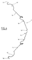
- the bottom wall 3 a horizontal section of which is shown in FIG. 4, is here composed of a central panel 15 flanked by two symmetrical side panels.
- the central panel 15 or corner panel, facing an angle of the room to equip, has a curvilinear section whose concavity is turned inward of the cabin and which here includes recesses 18 intended in particular for mounting of the accessories 22 (in particular the taps 22a) indicated in FIG. 1.
- the central panel 15 For its removable assembly to each of the side panels 16, 17, of which the detail is represented in FIG. 5 for the panel 17, the central panel 15 has on each of its vertical edges a tuck-in fold 19, which is extended by a angled elbow having two branches 20 and 21, orthogonal. This last branch 21, which constitutes a free edge of the central panel 15, is parallel to the vertical plane of symmetry of the shower cabin.
- the free edge of the side panel 17 has a re-entrant fold 23 parallel, in the assembly position, to the branch 21 of the panel 15 extended by a angled elbow having two orthogonal branches 24, 25, the branch 24, adjacent at the fold 23, being parallel, in the assembly position, to the branch 20.
- the branch 20 of the panel 15 and the branch 24 of the panel 17 are drilled with holes 28, 29, respectively, corresponding two by two for the screw passage 30.
- each side panel 16, 17 has, opposite its region assembly to the central panel, a flange 56 intended, as will be seen below, the fixing of the bottom wall to the shower wall.
- each side panel 16, 17, has a niche 40, intended to receive, if necessary, side showers 41 hydromassage for example.
- each niche 40 is equipped with a strip 42, which receives the showers and is fixed, for example in the upper and lower parts of the niche, by means of self-tapping screws 43. These strips 42 are thus removable from inside the cabin and allow convenient access to a possibly defective equipment.
- Shelves 45 can advantageously be provided during the preparation side panels 16, 17. Likewise, shelves or a bench seat 46 may be provided during the manufacture of the bottom panel 15.
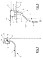
- Figure 7 illustrates the mounting of a shower screen (not shown) on the receiver 2.
- the rib 13 receives a profile 50 or crosspiece, which covers it with a groove 51 of its lower part.
- a housing 52, intended to receive a window with its seal is provided at the upper part of this profile 50. This arrangement allows a assembly on the receiver 2 without adding sealant.
- Figure 8 shows the junction of the shower wall 4 with a side panel 17 of the bottom wall of the cabin according to the invention.
- the cross member 50 is joined to its end 53 to a post 54 also consisting of a cross-section profile U-shaped, which is fixed by means of screws 55 for example, along a edge 56 of side panel 16 or 17 (see Figures 4, 6 and 8), through the bottom of the U.
- This upright 54 is fixed to the cross-member 50 by any appropriate means, for example screws 57 passing through a U-shaped upright and entering appropriate housings 58 of the cross member 50 ( Figure 7).
- An adjustable finishing strip 60 is clipped onto the upright 54 and extends to the wall of the room. The removal of this wand provides access to the fixing screws 55 on the side panel, without moving the cabin.
- the configuration of the profile or upright 54 ensures a seal without joint or sealant: for this a rib 61 is formed on the bottom of the U-shaped profile 54, this rib 61 covering the edge of the side panel 16 or 17 provided with a chamfer and thus constituting with the chamfer of the panel a passage in baffle 62.
- the arrow 64 indicates the path of the water in the groove dug in the catcher (see Figure 2).
- Figure 9 shows how water that could seep under or behind the bottom panels is stopped by the ledge and channeled into the recovery groove opening into the receiver tray on the edges of the side panels.
- a cap 70 ( Figure 1). This cap, made by thermoforming or any other technique, is also removable from inside the cabin, without movement of the receiver 2.
- a remote control for example an infrared remote control adapted in particular to control the various functions used in an installation or system hydromassage.
- a remote control allows in particular the preheating of the shower and start-up of the hammam from outside the cabin. She permits also easier use, in a seated position, of the hydromassage system.
- a remote control system can be provided for any type of shower cubicles regardless of the structure of the panels and the shower tray and assembly means described above.
Landscapes
- Health & Medical Sciences (AREA)
- Public Health (AREA)
- Epidemiology (AREA)
- General Health & Medical Sciences (AREA)
- Bathtubs, Showers, And Their Attachments (AREA)
- Residential Or Office Buildings (AREA)
Applications Claiming Priority (2)
| Application Number | Priority Date | Filing Date | Title |
|---|---|---|---|
| FR0006916 | 2000-05-30 | ||
| FR0006916A FR2809609B1 (fr) | 2000-05-30 | 2000-05-30 | Cabine de douche |
Publications (1)
| Publication Number | Publication Date |
|---|---|
| EP1159909A1 true EP1159909A1 (de) | 2001-12-05 |
Family
ID=8850777
Family Applications (1)
| Application Number | Title | Priority Date | Filing Date |
|---|---|---|---|
| EP01401403A Withdrawn EP1159909A1 (de) | 2000-05-30 | 2001-05-29 | Duschkabine |
Country Status (2)
| Country | Link |
|---|---|
| EP (1) | EP1159909A1 (de) |
| FR (1) | FR2809609B1 (de) |
Cited By (3)
| Publication number | Priority date | Publication date | Assignee | Title |
|---|---|---|---|---|
| FR2842551A1 (fr) * | 2002-07-17 | 2004-01-23 | Sotrenep | Ensemble de plaques a assembler notamment pour cabine de douche |
| FR2880788A1 (fr) * | 2005-01-19 | 2006-07-21 | Aquaproduction Soc Par Actions | Cabine de douche, dite gravitaire |
| WO2010108441A1 (en) * | 2009-03-25 | 2010-09-30 | Chesta Chan | Exposed shower system |
Citations (6)
| Publication number | Priority date | Publication date | Assignee | Title |
|---|---|---|---|---|
| US2389724A (en) * | 1943-12-27 | 1945-11-27 | Dextone Company | Shower stall |
| US2648409A (en) * | 1945-12-27 | 1953-08-11 | Sanymetal Products Co Inc | Shower cabinet |
| DE2324083A1 (de) * | 1973-05-12 | 1974-11-21 | Julius Wege | Halterung fuer brausearmaturen |
| US4152789A (en) * | 1977-11-25 | 1979-05-08 | Vbm Corporation | Shower stall enclosure |
| EP0501263A2 (de) * | 1991-03-01 | 1992-09-02 | Hansa Metallwerke Ag | Einrichtung zur berührungslosen Steuerung einer Dusche |
| DE9303155U1 (de) * | 1993-03-04 | 1993-04-22 | Koralle Sanitärprodukte GmbH & Co, 4973 Vlotho | Duschkabine |
-
2000
- 2000-05-30 FR FR0006916A patent/FR2809609B1/fr not_active Expired - Fee Related
-
2001
- 2001-05-29 EP EP01401403A patent/EP1159909A1/de not_active Withdrawn
Patent Citations (6)
| Publication number | Priority date | Publication date | Assignee | Title |
|---|---|---|---|---|
| US2389724A (en) * | 1943-12-27 | 1945-11-27 | Dextone Company | Shower stall |
| US2648409A (en) * | 1945-12-27 | 1953-08-11 | Sanymetal Products Co Inc | Shower cabinet |
| DE2324083A1 (de) * | 1973-05-12 | 1974-11-21 | Julius Wege | Halterung fuer brausearmaturen |
| US4152789A (en) * | 1977-11-25 | 1979-05-08 | Vbm Corporation | Shower stall enclosure |
| EP0501263A2 (de) * | 1991-03-01 | 1992-09-02 | Hansa Metallwerke Ag | Einrichtung zur berührungslosen Steuerung einer Dusche |
| DE9303155U1 (de) * | 1993-03-04 | 1993-04-22 | Koralle Sanitärprodukte GmbH & Co, 4973 Vlotho | Duschkabine |
Cited By (3)
| Publication number | Priority date | Publication date | Assignee | Title |
|---|---|---|---|---|
| FR2842551A1 (fr) * | 2002-07-17 | 2004-01-23 | Sotrenep | Ensemble de plaques a assembler notamment pour cabine de douche |
| FR2880788A1 (fr) * | 2005-01-19 | 2006-07-21 | Aquaproduction Soc Par Actions | Cabine de douche, dite gravitaire |
| WO2010108441A1 (en) * | 2009-03-25 | 2010-09-30 | Chesta Chan | Exposed shower system |
Also Published As
| Publication number | Publication date |
|---|---|
| FR2809609A1 (fr) | 2001-12-07 |
| FR2809609B1 (fr) | 2002-08-30 |
Similar Documents
| Publication | Publication Date | Title |
|---|---|---|
| EP2341809A1 (de) | Niveaugleiche duschvorrichtung mit umgebendem boden | |
| EP1159909A1 (de) | Duschkabine | |
| FR2498241A1 (fr) | Cloison de separation de douche | |
| CA2635939A1 (fr) | Carter de protection et de masquage d'une cuvette de toilettes et cuvette ainsi equipee | |
| EP1803887B1 (de) | Kasten mit Rolladen und Fensterrahmenblock | |
| US20190345702A1 (en) | Lavatory with hidden drain | |
| FR2695632A1 (fr) | Plafond intégré pour cabine d'ascenseur. | |
| EP0840069B1 (de) | Firststruktur | |
| FR2598163A1 (fr) | Procede de pre-fabrication permettant l'utilisation de tous les appareils sanitaires existant pour la creation de salles d'eau | |
| FR2518465A1 (fr) | Toit ouvrant de vehicule | |
| FR2735674A1 (fr) | Ensemble sanitaire modulaire | |
| EP3501357B1 (de) | Duschkonstruktion | |
| FR2654606A3 (fr) | Cabine de douche en elements prefabriques. | |
| BE1016467A3 (fr) | Systeme d'amenagement pour emplacement de douche. | |
| FR2690186A1 (fr) | Dispositif de recouvrement d'une tranche verticale d'un élément de construction en suspens. | |
| FR2799058A1 (fr) | Adaptateur pour appareillage electrique presentant un sens de montage | |
| FR2707472A1 (fr) | Ensemble mobilier modulaire pour sanitaires. | |
| FR2860411A1 (fr) | Ensemble de receveur de douche et cabine associee | |
| EP2835081B1 (de) | Sanitäre Vorrichtung und ihr Einbauverfahren | |
| FR2493127A1 (fr) | Appareil sanitaire comportant un rebord perfectionne | |
| FR3133211A1 (fr) | Menuiserie équipée d’un volet roulant accessible de l’intérieur | |
| CA2324497A1 (fr) | Installation sanitaire et dispositif de vidange pour une telle installation | |
| FR3145857A3 (fr) | Utilisation d’une paroi dans une douche ou baignoire, et douche ou baignoire munie d’une telle paroi | |
| FR2502670A1 (fr) | Materiau pour le recouvrement et la decoration de parois diverses et plus particulierement de portes pliantes | |
| FR2946296A1 (fr) | Vehicule automobile notamment utilitaire, comportant une cellule arriere equipee de panneaux amovibles |
Legal Events
| Date | Code | Title | Description |
|---|---|---|---|
| PUAI | Public reference made under article 153(3) epc to a published international application that has entered the european phase |
Free format text: ORIGINAL CODE: 0009012 |
|
| AK | Designated contracting states |
Kind code of ref document: A1 Designated state(s): AT BE CH CY DE DK ES FI FR GB GR IE IT LI LU MC NL PT SE TR |
|
| AX | Request for extension of the european patent |
Free format text: AL;LT;LV;MK;RO;SI |
|
| 17P | Request for examination filed |
Effective date: 20020502 |
|
| AKX | Designation fees paid |
Free format text: AT BE CH CY DE DK ES FI FR GB GR IE IT LI LU MC NL PT SE TR |
|
| 17Q | First examination report despatched |
Effective date: 20050223 |
|
| STAA | Information on the status of an ep patent application or granted ep patent |
Free format text: STATUS: THE APPLICATION IS DEEMED TO BE WITHDRAWN |
|
| 18D | Application deemed to be withdrawn |
Effective date: 20050906 |