EP1159933B1 - Aktiver arterieller Embolisierungsblutfilter - Google Patents
Aktiver arterieller Embolisierungsblutfilter Download PDFInfo
- Publication number
- EP1159933B1 EP1159933B1 EP01112077A EP01112077A EP1159933B1 EP 1159933 B1 EP1159933 B1 EP 1159933B1 EP 01112077 A EP01112077 A EP 01112077A EP 01112077 A EP01112077 A EP 01112077A EP 1159933 B1 EP1159933 B1 EP 1159933B1
- Authority
- EP
- European Patent Office
- Prior art keywords
- gutter
- motor
- paddles
- guide wire
- deployed position
- Prior art date
- Legal status (The legal status is an assumption and is not a legal conclusion. Google has not performed a legal analysis and makes no representation as to the accuracy of the status listed.)
- Expired - Lifetime
Links
- 230000010108 arterial embolization Effects 0.000 title 1
- 230000017531 blood circulation Effects 0.000 claims description 17
- 208000007536 Thrombosis Diseases 0.000 claims description 16
- 239000008280 blood Substances 0.000 claims description 12
- 210000004369 blood Anatomy 0.000 claims description 12
- 230000008859 change Effects 0.000 claims description 2
- 230000003213 activating effect Effects 0.000 claims 1
- 239000003999 initiator Substances 0.000 description 13
- 238000002399 angioplasty Methods 0.000 description 3
- 210000001715 carotid artery Anatomy 0.000 description 3
- 230000009471 action Effects 0.000 description 2
- 230000004913 activation Effects 0.000 description 2
- 230000004888 barrier function Effects 0.000 description 2
- 239000013013 elastic material Substances 0.000 description 2
- 230000010102 embolization Effects 0.000 description 2
- 239000004744 fabric Substances 0.000 description 2
- 230000003902 lesion Effects 0.000 description 2
- 208000032109 Transient ischaemic attack Diseases 0.000 description 1
- 210000001367 artery Anatomy 0.000 description 1
- 210000004556 brain Anatomy 0.000 description 1
- 239000000919 ceramic Substances 0.000 description 1
- 230000001419 dependent effect Effects 0.000 description 1
- 238000000034 method Methods 0.000 description 1
- 230000004048 modification Effects 0.000 description 1
- 238000012986 modification Methods 0.000 description 1
- 239000002245 particle Substances 0.000 description 1
- 238000009958 sewing Methods 0.000 description 1
- 201000010875 transient cerebral ischemia Diseases 0.000 description 1
- XLYOFNOQVPJJNP-UHFFFAOYSA-N water Substances O XLYOFNOQVPJJNP-UHFFFAOYSA-N 0.000 description 1
Images



Classifications
-
- A—HUMAN NECESSITIES
- A61—MEDICAL OR VETERINARY SCIENCE; HYGIENE
- A61M—DEVICES FOR INTRODUCING MEDIA INTO, OR ONTO, THE BODY; DEVICES FOR TRANSDUCING BODY MEDIA OR FOR TAKING MEDIA FROM THE BODY; DEVICES FOR PRODUCING OR ENDING SLEEP OR STUPOR
- A61M1/00—Suction or pumping devices for medical purposes; Devices for carrying-off, for treatment of, or for carrying-over, body-liquids; Drainage systems
- A61M1/34—Filtering material out of the blood by passing it through a membrane, i.e. hemofiltration or diafiltration
-
- A—HUMAN NECESSITIES
- A61—MEDICAL OR VETERINARY SCIENCE; HYGIENE
- A61F—FILTERS IMPLANTABLE INTO BLOOD VESSELS; PROSTHESES; DEVICES PROVIDING PATENCY TO, OR PREVENTING COLLAPSING OF, TUBULAR STRUCTURES OF THE BODY, e.g. STENTS; ORTHOPAEDIC, NURSING OR CONTRACEPTIVE DEVICES; FOMENTATION; TREATMENT OR PROTECTION OF EYES OR EARS; BANDAGES, DRESSINGS OR ABSORBENT PADS; FIRST-AID KITS
- A61F2/00—Filters implantable into blood vessels; Prostheses, i.e. artificial substitutes or replacements for parts of the body; Appliances for connecting them with the body; Devices providing patency to, or preventing collapsing of, tubular structures of the body, e.g. stents
- A61F2/01—Filters implantable into blood vessels
-
- A—HUMAN NECESSITIES
- A61—MEDICAL OR VETERINARY SCIENCE; HYGIENE
- A61B—DIAGNOSIS; SURGERY; IDENTIFICATION
- A61B17/00—Surgical instruments, devices or methods
- A61B2017/00367—Details of actuation of instruments, e.g. relations between pushing buttons, or the like, and activation of the tool, working tip, or the like
- A61B2017/00398—Details of actuation of instruments, e.g. relations between pushing buttons, or the like, and activation of the tool, working tip, or the like using powered actuators, e.g. stepper motors, solenoids
-
- A—HUMAN NECESSITIES
- A61—MEDICAL OR VETERINARY SCIENCE; HYGIENE
- A61B—DIAGNOSIS; SURGERY; IDENTIFICATION
- A61B17/00—Surgical instruments, devices or methods
- A61B17/22—Implements for squeezing-off ulcers or the like on inner organs of the body; Implements for scraping-out cavities of body organs, e.g. bones; for invasive removal or destruction of calculus using mechanical vibrations; for removing obstructions in blood vessels, not otherwise provided for
- A61B2017/22072—Implements for squeezing-off ulcers or the like on inner organs of the body; Implements for scraping-out cavities of body organs, e.g. bones; for invasive removal or destruction of calculus using mechanical vibrations; for removing obstructions in blood vessels, not otherwise provided for with an instrument channel, e.g. for replacing one instrument by the other
- A61B2017/22074—Implements for squeezing-off ulcers or the like on inner organs of the body; Implements for scraping-out cavities of body organs, e.g. bones; for invasive removal or destruction of calculus using mechanical vibrations; for removing obstructions in blood vessels, not otherwise provided for with an instrument channel, e.g. for replacing one instrument by the other the instrument being only slidable in a channel, e.g. advancing optical fibre through a channel
- A61B2017/22075—Implements for squeezing-off ulcers or the like on inner organs of the body; Implements for scraping-out cavities of body organs, e.g. bones; for invasive removal or destruction of calculus using mechanical vibrations; for removing obstructions in blood vessels, not otherwise provided for with an instrument channel, e.g. for replacing one instrument by the other the instrument being only slidable in a channel, e.g. advancing optical fibre through a channel with motorized advancing or retracting means
-
- A—HUMAN NECESSITIES
- A61—MEDICAL OR VETERINARY SCIENCE; HYGIENE
- A61F—FILTERS IMPLANTABLE INTO BLOOD VESSELS; PROSTHESES; DEVICES PROVIDING PATENCY TO, OR PREVENTING COLLAPSING OF, TUBULAR STRUCTURES OF THE BODY, e.g. STENTS; ORTHOPAEDIC, NURSING OR CONTRACEPTIVE DEVICES; FOMENTATION; TREATMENT OR PROTECTION OF EYES OR EARS; BANDAGES, DRESSINGS OR ABSORBENT PADS; FIRST-AID KITS
- A61F2230/00—Geometry of prostheses classified in groups A61F2/00 - A61F2/26 or A61F2/82 or A61F9/00 or A61F11/00 or subgroups thereof
- A61F2230/0002—Two-dimensional shapes, e.g. cross-sections
- A61F2230/0004—Rounded shapes, e.g. with rounded corners
- A61F2230/0006—Rounded shapes, e.g. with rounded corners circular
Definitions
- This invention relates to an apparatus for collecting emboli flowing in a limen.
- Another such conventional device is an umbrella like filter placed distal to the lesion being treated.
- a major shortcoming of these conventional filters is that these conventional filters or barriers may greatly reduce, or even block, the downstream flow of blood from the treated artery to the brain, e.g., in the carotid artery.
- Another shortcoming of these devices is that they are passive.
- OCM Miniature Oscillating Ceramic Motors
- U.S. patent 5,453,653 to Zumeris These motors can be made very small and in any shape and they operate by contacting a surface in an amount sufficient to generate sufficient friction to permit the motor to "crawl" along the contacted surface and change its position relative to the contacted surface when the motor is energized.
- These motors can be adequately insulated to act in aqueous environments. Their small size and low energy level requirements make them especially suitable for use inside living organisms.
- FIG. 1 is a lateral perspective of a portion of one embodiment of the invention and shows a cylindrical motor 1 having a longitudinal bore 5 there through.
- a guide wire 2 is disposed within the longitudinal bore 5.
- FIG. 2 is a cross-sectional end view taken on line A-A of FIG. 1 and shows the motor 1, preferably cylindrical, having an outer surface 3 and an inner surface 4 defining a longitudinal bore 5.
- the inner surface 4 defining the longitudinal bore 5 is provided with a friction area 6 adapted to engage the guide wire 2.
- the longitudinal bore 5 and the guide wire 2 are sized and adapted so that when the motor 1 is energized the friction area 6 engages the guide wire 2 and the motor 1 will rotate around the longitudinal axis 52 of the guide wire 2, thus, changing its position relative to the guide wire 2.
- a biasing means e.g., a leaf spring 7 is utilized to bias the guide wire 2 against the friction area 6 of the motor 1.
- FIG. 3 is a side-view of a preferred embodiment of an invention that utilizes the motor and guide wire shown in FIGS. 1 and 2.
- FIG. 3A is an end-view of FIG. 3 taken along line A-A of FIG. 3.
- a plurality of selectively deployable paddles 8 is attached to the motor 1.
- the paddles 8 are adapted to be selectively movable between a first collapsed or stored position 9 when the motor 1 is not energized and a second or deployed position 10 when the motor 1 is energized.
- a wide variety of means well known to those skilled in the art as suitable for selectively moving the paddles 8 between the first stored position 9 and the second deployed position 10 may be utilized.
- the paddles 8 may be made of an elastic material and may be moved from the first stored position 9 to the second deployed position 10 under their own elastic force after a locking wire 11 is released. After the treatment has been completed, the locking wire 11 may be activated to move the paddles 8 from the second deployed position 10 to the first stored position 9 to facilitate removal.
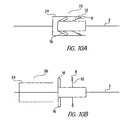
- a sheath 24 selectively moveable along the longitudinal axis of the guidewire 2 is utilized to selectively move the paddles 8 between the first or stored position 9 to the second or deployed position 10. As shown in FIG. 10a, when the sheath 24 is in the first position 25 the paddles 8 are disposed in the first or stored position 9 and as shown in FIG.
- the paddles 8 when the sheath 24 is disposed in the second position 26 the paddles 8 are free to move to the second or deployed position 10.
- the paddles 8 are returned to the first or stored position by moving the sheath 24 to the first position 25.
- the paddles 8 may be attached to arms 12 that are connected to the motor 1 via springs 13 as shown in FIG. 4.
- the paddles 8 are directly connected to the motor 1 via springs 14 as shown in FIG. 5.
- the paddles 8 are connected to arms 12 that are hingedly connected to the motor 1 and the arms 12 are provided with springs 15, as shown in FIG. 6, that normally keep the arms 12 and the paddles 8 in the first stored position 9.
- the paddles are sized and adapted so that when the motor 1 is energized and begins to rotate around the longitudinal axis of the guide wire 2, the centrifugal force of the rotating motor 1 causes the paddles 8 to move from the first stored position 9 to the second deployed position 10 and when the motor 1 stops rotating the absence of centrifugal force causes the paddles 8 to move to the first or stored position 9.
- the paddles 8 are sized and shaped so that as they rotate they initiate a spiral blood flood in the blood passing through the lumen. The swirling or cyclonic action caused by the rotating paddles 8 causes the emboli to flow towards the wall of the lumen and hug the lumen as the emboli travel with the blood flowing through the lumen.
- the emboli are then collected by a gutter positioned around the internal surface of the lumen.
- the gutter traps the emboli but allows blood to flow through the center of the lumen.
- a thrombus collecting gutter 16 having a closed bottom end 17 and an open top end 18 is disposed distal to the paddles 8.
- the thrombus collecting gutter 16 may be disposed on the motor or the guidewire and is adapted for selective movement between a first collapsed or stored position 19 and a second deployed position 20 as shown in FIG. 3.
- a wide variety of means well known to those skilled in the art as suitable for selectively moving the thrombus collecting gutter 16 between the first stored position and the second deployed position 20 may be utilized as previously discussed with respect to moving the paddles 8 from the first or stored position to the second or deployed position.
- the thrombus collecting gutter 16 is made of an elastic material and may be moved from the first stored position 19 to the second deployed position 20 under its own elastic force after a locking wire 11' is released. In another embodiment, the thrombus collecting gutter 16 is moved to the second or deployed position 20 by centrifugal force created by the rotating motor 1. In yet another embodiment a selectively movable sheath 24 is used to selectively move both the gutter and the paddles between a first stored position and a second deployed position as previously discussed and as shown in FIGS. 10A and 10B.
- the thrombus collecting gutter 16 When the thrombus collecting gutter 16 is in the first or stored position 19 it has a narrow streamlined configuration that permits it to be easily and safely disposed in and removed from the target area.
- the thrombus collecting gutter 16 has a substantially "U" shaped cross-sectional configuration, as shown in FIGS. 3, 7, and 8, when in the second deployed position 20 and an external diameter that is substantially equal to the internal diameter of the lumen being treated.
- the open top end 18 is disposed between the bottom end 17 of the gutter 16 and the paddles 8, i.e., the open end 18 of the "U" faces the paddles 8 to permit thrombi diverted by the paddles to be trapped in the gutter 16.
- the top or open end 18 of the gutter 16 is adapted so that it may be selectively opened and closed and is provided with a means 21 for selectively opening and closing the top end of the gutter.
- the means 21 for selectively opening and closing the gutter may be selected from a wide variety of means well known to those skilled in the art as suitable for this purpose, however, in a preferred embodiment a trip wire 21 disposed along the periphery of the top end of the gutter is utilized. Alternatively, the trip wire 21 may be embedded within the top end 18 of the gutter as shown in FIG. 8.
- the trip wire 21 is preferably connected to an activation means such as a lever or a wire 22 for selectively opening and closing the top end 18 of the gutter 16.
- the top end 18 of the gutter 16 is provided with a wire or filament 23 that traverses the open end of the gutter for selectively opening and closing the open top end 18 of the gutter 16 as shown in FIG 9.
- an activation means such as a lever or wire 22
- the wire or filament 23 causes the open end 18 of the gutter 16 to close in the same way that pulling on a sewing thread connecting two pieces of cloth causes the two pieces of cloth to move closer to each other.
- the apparatus is constructed, mounted on a guide wire and is manually advanced to the target area which is downstream from the area that is being treated.
- the motor is then energized to activate the motor friction area which causes the motor to rotate around the longitudinal axis of the guide wire.
- the centrifugal force created by the rotating motor causes the gutter and the paddles to move from the first stored position to the second deployed position with the open end of the gutter facing the paddles.
- the rotating paddles create a swirling action or spiral blood flow in the blood like a propeller rotating in water which causes emboli in the blood to flow toward and be propelled against the internal wall of the lumen.
- the emboli hug the internal wall of the lumen as the blood forces them downstream and into the open end of the gutter.
- the motor When the treatment is complete the motor is de-energized which causes the motor to stop rotating and causes the paddles and the gutter to return to the first collapsed or stored position.
- a gutter whose open top end may be selectively opened and closed.
- the open top end of the gutter may be closed before it is moved from the second deployed position to the first stored position to help retain the trapped emboli and reduce the likelihood that they will spill out of the gutter into the bloodstream as the apparatus is removed from the lumen.
- the apparatus may then be manually removed by pulling on the guide wire.
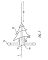
- Figure 7 shows another preferred embodiment of the invention and shows a motor 50, preferably cylindrically shaped, having a longitudinal bore 51 sized and adapted to permit selective movement of the motor 50 around the longitudinal axis 52 of a guide wire 2 disposed within the longitudinal bore 51.
- a spiral blood flow initiator 53 is attached to the motor 50 and is adapted to permit the spiral blood flow initiator 53 to be selectively moved between a first collapsed or stored position 54 to a second deployed position 55.
- the spiral blood flow initiator 53 is also sized and adapted to initiate a spiral or cyclonic blood flow sufficient to deflect any emboli in the flowing blood towards the internal wall of the lumen in which the blood is flowing.
- a thrombus collecting gutter 16 is disposed either on the motor 50 or the guidewire 2 distal to the spiral blood flow initiator 53 with the open top end 18 of the gutter 16 disposed between the closed bottom end 17 of the gutter 16 and the spiral blood flow initiator 53 when the gutter 16 and the spiral blood flow initiator 53 are in the deployed second position 55.
- Means are provided for selectively moving the spiral blood flow initiator and the gutter between the first stored position and the second deployed position as previously discussed.
- a rotating motor 50 is utilized to create centrifugal force to both deploy and retract both the gutter 16 and the spiral blood flow initiator 53 as previously discussed.
- the device In operation, the device is advanced to the target area and the spiral blood flow initiator 53 and the gutter 16 are moved from the first position 19 and 54 to the second or deployed position 20 and 55.
- the spiral blood flow initiator 53 initiates a spiral or cyclonic blood flow which deflects or propels emboli against the internal wall of the lumen so that they can be trapped in the gutter 16 as previously discussed.
- the gutter 16 and the spiral blood flow initiator 53 are then returned to the first collapsed or stored position 19 and 54 and the apparatus is withdrawn from the target area.
- the gutter may be adapted to be selectively opened and closed as previously discussed.
Landscapes
- Health & Medical Sciences (AREA)
- Heart & Thoracic Surgery (AREA)
- Life Sciences & Earth Sciences (AREA)
- Veterinary Medicine (AREA)
- Engineering & Computer Science (AREA)
- Biomedical Technology (AREA)
- Public Health (AREA)
- Vascular Medicine (AREA)
- General Health & Medical Sciences (AREA)
- Animal Behavior & Ethology (AREA)
- Cardiology (AREA)
- Oral & Maxillofacial Surgery (AREA)
- Transplantation (AREA)
- Anesthesiology (AREA)
- Hematology (AREA)
- Surgical Instruments (AREA)
- External Artificial Organs (AREA)
- Processing Of Meat And Fish (AREA)
Claims (10)
- Vorrichtung zum Sammeln von Embolien, welche in einem Lumen fließen, aufweisend:a) einen Motor (1), welcher ein proximales Ende und ein distales Ende aufweist, wobei der Motor (1) eine Längsbohrung (4) aufweist, wobei der Motor (1) mit einem Motor-Friktionsbereich (6) versehen ist, welcher innerhalb der Längsbohrung (4) angeordnet ist, wobei der Motor-Friktionsbereich (6) angepasst ist, um eine selektive Bewegung des Motors (1) um die longitudinale Achse eines Führungsdrahtes (2) zu erlauben, welcher in der Längsbohrung (4) angeordnet ist;b) einen Führungsdraht (2), welcher eine longitudinale Achse aufweist, welche innerhalb der Längsbohrung (4) angeordnet ist, wobei der Führungsdraht (2) und die Längsbohrung (4) abgemessen und anpasst sind, um Reibung zwischen dem Friktionsbereich (6) des Motors (1) und dem Führungsdraht (2) in einem Betrag zu übertragen, der ausreichend ist, um es dem Motor (1) zu erlauben, die Position relativ zum Führungsdraht (2) durch ein Rotieren um die longitudinale Achse des Führungsdrahtes (2) zu verändern, wenn der Motor mit Energie versorgt wird;c) eine Vielzahl von selektiv entfaltbaren Schaufeln (8), welche an dem Motor (1) angebracht sind, wobei die Schaufeln (8) angepasst sind zur selektiven Bewegung zwischen einer ersten gelagerten Position (9) und einer zweiten entfalteten Position (10), wobei die Schaufeln (8) weiterhin angepasst sind, um eine wirbelnde Blutströmung von Blut, welches durch ein Lumen fließt, zu initiieren, um Embolien in Richtung der inneren Wand des Lumens abzulenken, wenn die Schaufeln (8) in der zweiten entfalteten Position (10) sind; undd) eine Thrombose-sammelnde Rinne (16), welche ein geschlossenes distales Ende (17) und ein offenes proximales Ende (18) aufweist, wobei die Rinne (16) angepasst ist zur selektiven Bewegung zwischen einer ersten gelagerten Position (19) und einer zweiten entfalteten Position (20), wobei die Rinne (16) auf dem Führungsdraht (2) distal zu den Schaufeln (8) angeordnet ist, wenn die Rinne (16) und die Schaufeln (8) in der entfalteten zweiten Position (20, 10) sind, wobei das offene proximale Ende (18) der Rinne (16) zwischen dem geschlossenen distalen Ende (17) der Rinne (16) und den Schaufeln (18) angeordnet ist, wenn die Rinne (16) in der entfalteten zweiten Position (20) angeordnet ist; unde) Einrichtungen zur selektiven Energieversorgung des Motors (1) und zum Aktivieren des Motor-Friktionsbereichs (6).
- Vorrichtung gemäß Anspruch 1, weiter aufweisend:f) Einrichtungen (11, 24) für das selektive Bewegen der Schaufeln (8) zwischen der ersten gelagerten Position (9) und der zweiten entfalteten Position (10); undg) Einrichtungen (11', 24) für das selektive Bewegen der Thrombose-sammelnden Rinne (16) zwischen der ersten gelagerten Position (19) und der zweiten entfalteten Position (20).
- Vorrichtung gemäß Anspruch 2, wobei die Einrichtungen für das selektive Bewegen der Schaufeln (8) zwischen der ersten gelagerten Position (9) und der zweiten entfalteten Position (10) und die Einrichtungen für das selektive Bewegen der Thrombose-sammelnden Rinne (16) zwischen der ersten gelagerten Position (19) und der zweiten entfalteten Position (20) jeweils ein Sicherungsdraht (11, 11') sind.
- Vorrichtung gemäß Anspruch 2, wobei die Einrichtungen für das selektive Bewegen der Schaufeln (8) zwischen der ersten gelagerten Position (9) und der zweiten entfalteten Position (10) und die Einrichtungen für das selektive Bewegen der Thrombose-sammelnden Rinne (16) zwischen der ersten gelagerten Position (19) und der zweiten entfalteten Position (20) eine Hülse (24) sind, geeignet für eine Bewegung längs der longitudinalen Achse des Führungsdrahtes (2) zwischen einer ersten Position, welche die Schaufeln (8) und die Rinne (16) in der ersten oder gelagerten Position (9, 19) zurückhält, und einer zweiten Position, welche es den Schaufeln (8) und der Rinne (16) erlaubt, sich zu der zweiten oder entfalteten Position (10, 20) zu bewegen.
- Vorrichtung gemäß Anspruch 2, wobei die Einrichtungen für das selektive Bewegen der Schaufeln (8) zwischen der ersten gelagerten Position (9) und der zweiten entfalteten Position (10) und die Einrichtungen für das selektive Bewegen der Thrombose-sammelnden Rinne (16) zwischen der ersten gelagerten Position (19) und der zweiten entfalteten Position (20) die Zentrifugalkraft sind, welche sich aus der Rotation des Motors (1) um die longitudinale Achse des Führungsdrahtes (2) ergibt.
- Vorrichtung gemäß einem der Ansprüche 1 bis 5, wobei die Rinne (16) weiterhin angepasst ist, so dass das offene proximale Ende (18) selektiv geöffnet und geschlossen werden kann, und mit Einrichtungen (21) versehen ist zum selektiven Öffnen und Schließen des proximalen Endes (18) der Rinne (16).
- Vorrichtung gemäß Anspruch 6, wobei die Einrichtungen zum selektiven Öffnen und Schließen des proximalen Endes (18) der Rinne (16) ein Auslösedraht (21) sind.
- Vorrichtung gemäß irgendeinem vorhergehenden Anspruch, welche weiterhin eine Vorspanneinrichtung (7) aufweist, um den Führungsdraht gegen den Friktionsbereich (6) vorzuspannen.
- Vorrichtung gemäß Anspruch 8, wobei die Vorspanneinrichtung eine Blattfeder (7) ist.
- Vorrichtung gemäß irgendeinem vorhergehenden Anspruch, wobei der Motor (1) zylindrisch ausgebildet ist.
Applications Claiming Priority (2)
| Application Number | Priority Date | Filing Date | Title |
|---|---|---|---|
| US09/583,363 US6645221B1 (en) | 2000-05-30 | 2000-05-30 | Active arterial embolization filter |
| US583363 | 2000-05-30 |
Publications (3)
| Publication Number | Publication Date |
|---|---|
| EP1159933A2 EP1159933A2 (de) | 2001-12-05 |
| EP1159933A3 EP1159933A3 (de) | 2003-08-13 |
| EP1159933B1 true EP1159933B1 (de) | 2006-09-27 |
Family
ID=24332809
Family Applications (1)
| Application Number | Title | Priority Date | Filing Date |
|---|---|---|---|
| EP01112077A Expired - Lifetime EP1159933B1 (de) | 2000-05-30 | 2001-05-28 | Aktiver arterieller Embolisierungsblutfilter |
Country Status (25)
| Country | Link |
|---|---|
| US (2) | US6645221B1 (de) |
| EP (1) | EP1159933B1 (de) |
| JP (1) | JP3613790B2 (de) |
| KR (1) | KR100426823B1 (de) |
| CN (1) | CN1330913A (de) |
| AR (1) | AR031587A1 (de) |
| AT (1) | ATE340539T1 (de) |
| AU (2) | AU775619C (de) |
| BR (1) | BR0102182A (de) |
| CA (1) | CA2348972A1 (de) |
| CZ (1) | CZ20011838A3 (de) |
| DE (2) | DE10125769A1 (de) |
| EE (1) | EE200100289A (de) |
| GB (1) | GB2365353B (de) |
| HK (1) | HK1041631A1 (de) |
| IL (1) | IL143371A0 (de) |
| MX (1) | MXPA01005416A (de) |
| NO (1) | NO20012621L (de) |
| NZ (1) | NZ511972A (de) |
| PL (1) | PL347778A1 (de) |
| RU (1) | RU2221599C2 (de) |
| SG (1) | SG87931A1 (de) |
| SK (1) | SK7282001A3 (de) |
| UA (1) | UA67812C2 (de) |
| WO (1) | WO2001091824A2 (de) |
Families Citing this family (107)
| Publication number | Priority date | Publication date | Assignee | Title |
|---|---|---|---|---|
| US7094249B1 (en) | 1997-03-06 | 2006-08-22 | Boston Scientific Scimed, Inc. | Distal protection device and method |
| US6974469B2 (en) | 1997-03-06 | 2005-12-13 | Scimed Life Systems, Inc. | Distal protection device and method |
| US6676682B1 (en) | 1997-05-08 | 2004-01-13 | Scimed Life Systems, Inc. | Percutaneous catheter and guidewire having filter and medical device deployment capabilities |
| US6171327B1 (en) | 1999-02-24 | 2001-01-09 | Scimed Life Systems, Inc. | Intravascular filter and method |
| US7306618B2 (en) | 1999-07-30 | 2007-12-11 | Incept Llc | Vascular device for emboli and thrombi removal and methods of use |
| US6544279B1 (en) | 2000-08-09 | 2003-04-08 | Incept, Llc | Vascular device for emboli, thrombus and foreign body removal and methods of use |
| US6142987A (en) | 1999-08-03 | 2000-11-07 | Scimed Life Systems, Inc. | Guided filter with support wire and methods of use |
| US6235044B1 (en) | 1999-08-04 | 2001-05-22 | Scimed Life Systems, Inc. | Percutaneous catheter and guidewire for filtering during ablation of mycardial or vascular tissue |
| US6217589B1 (en) | 1999-10-27 | 2001-04-17 | Scimed Life Systems, Inc. | Retrieval device made of precursor alloy cable and method of manufacturing |
| US6575997B1 (en) | 1999-12-23 | 2003-06-10 | Endovascular Technologies, Inc. | Embolic basket |
| US6660021B1 (en) | 1999-12-23 | 2003-12-09 | Advanced Cardiovascular Systems, Inc. | Intravascular device and system |
| US6402771B1 (en) | 1999-12-23 | 2002-06-11 | Guidant Endovascular Solutions | Snare |
| US7918820B2 (en) | 1999-12-30 | 2011-04-05 | Advanced Cardiovascular Systems, Inc. | Device for, and method of, blocking emboli in vessels such as blood arteries |
| US6695813B1 (en) | 1999-12-30 | 2004-02-24 | Advanced Cardiovascular Systems, Inc. | Embolic protection devices |
| US6540722B1 (en) | 1999-12-30 | 2003-04-01 | Advanced Cardiovascular Systems, Inc. | Embolic protection devices |
| US7713227B2 (en) * | 2000-03-20 | 2010-05-11 | Michael Wholey | Method and apparatus for medical device for aspiration of thromboemobolic debris |
| US6645221B1 (en) * | 2000-05-30 | 2003-11-11 | Zuli, Holdings Ltd. | Active arterial embolization filter |
| US6964670B1 (en) | 2000-07-13 | 2005-11-15 | Advanced Cardiovascular Systems, Inc. | Embolic protection guide wire |
| US6537294B1 (en) | 2000-10-17 | 2003-03-25 | Advanced Cardiovascular Systems, Inc. | Delivery systems for embolic filter devices |
| US6893451B2 (en) | 2000-11-09 | 2005-05-17 | Advanced Cardiovascular Systems, Inc. | Apparatus for capturing objects beyond an operative site utilizing a capture device delivered on a medical guide wire |
| US6506203B1 (en) | 2000-12-19 | 2003-01-14 | Advanced Cardiovascular Systems, Inc. | Low profile sheathless embolic protection system |
| US7169165B2 (en) | 2001-01-16 | 2007-01-30 | Boston Scientific Scimed, Inc. | Rapid exchange sheath for deployment of medical devices and methods of use |
| US6936059B2 (en) | 2001-01-16 | 2005-08-30 | Scimed Life Systems, Inc. | Endovascular guidewire filter and methods of use |
| US6689151B2 (en) | 2001-01-25 | 2004-02-10 | Scimed Life Systems, Inc. | Variable wall thickness for delivery sheath housing |
| US6840950B2 (en) | 2001-02-20 | 2005-01-11 | Scimed Life Systems, Inc. | Low profile emboli capture device |
| US6974468B2 (en) | 2001-02-28 | 2005-12-13 | Scimed Life Systems, Inc. | Filter retrieval catheter |
| US7226464B2 (en) | 2001-03-01 | 2007-06-05 | Scimed Life Systems, Inc. | Intravascular filter retrieval device having an actuatable dilator tip |
| US20020123755A1 (en) | 2001-03-01 | 2002-09-05 | Scimed Life Systems, Inc. | Embolic protection filter delivery sheath |
| US7044952B2 (en) | 2001-06-06 | 2006-05-16 | Sdgi Holdings, Inc. | Dynamic multilock anterior cervical plate system having non-detachably fastened and moveable segments |
| US6599307B1 (en) | 2001-06-29 | 2003-07-29 | Advanced Cardiovascular Systems, Inc. | Filter device for embolic protection systems |
| US7338510B2 (en) | 2001-06-29 | 2008-03-04 | Advanced Cardiovascular Systems, Inc. | Variable thickness embolic filtering devices and method of manufacturing the same |
| US6638294B1 (en) | 2001-08-30 | 2003-10-28 | Advanced Cardiovascular Systems, Inc. | Self furling umbrella frame for carotid filter |
| US6592606B2 (en) | 2001-08-31 | 2003-07-15 | Advanced Cardiovascular Systems, Inc. | Hinged short cage for an embolic protection device |
| US8262689B2 (en) | 2001-09-28 | 2012-09-11 | Advanced Cardiovascular Systems, Inc. | Embolic filtering devices |
| US6755847B2 (en) | 2001-10-05 | 2004-06-29 | Scimed Life Systems, Inc. | Emboli capturing device and method of manufacture therefor |
| US6887257B2 (en) | 2001-10-19 | 2005-05-03 | Incept Llc | Vascular embolic filter exchange devices and methods of use thereof |
| US7052500B2 (en) | 2001-10-19 | 2006-05-30 | Scimed Life Systems, Inc. | Embolus extractor |
| GB2384189A (en) * | 2001-11-21 | 2003-07-23 | Tayside Flow Technologies Ltd | Helix shaped insert for flow moification in a duct or stent |
| US7153320B2 (en) | 2001-12-13 | 2006-12-26 | Scimed Life Systems, Inc. | Hydraulic controlled retractable tip filter retrieval catheter |
| US6793666B2 (en) | 2001-12-18 | 2004-09-21 | Scimed Life Systems, Inc. | Distal protection mechanically attached filter cartridge |
| US7241304B2 (en) | 2001-12-21 | 2007-07-10 | Advanced Cardiovascular Systems, Inc. | Flexible and conformable embolic filtering devices |
| US6932830B2 (en) | 2002-01-10 | 2005-08-23 | Scimed Life Systems, Inc. | Disc shaped filter |
| US6997938B2 (en) | 2002-02-12 | 2006-02-14 | Scimed Life Systems, Inc. | Embolic protection device |
| US7118539B2 (en) | 2002-02-26 | 2006-10-10 | Scimed Life Systems, Inc. | Articulating guide wire for embolic protection and methods of use |
| US7029440B2 (en) | 2002-03-13 | 2006-04-18 | Scimed Life Systems, Inc. | Distal protection filter and method of manufacture |
| US7060082B2 (en) | 2002-05-06 | 2006-06-13 | Scimed Life Systems, Inc. | Perfusion guidewire in combination with a distal filter |
| US7585309B2 (en) | 2002-05-16 | 2009-09-08 | Boston Scientific Scimed, Inc. | Aortic filter |
| US7001406B2 (en) | 2002-05-23 | 2006-02-21 | Scimed Life Systems Inc. | Cartridge embolic protection filter and methods of use |
| US7326224B2 (en) | 2002-06-11 | 2008-02-05 | Boston Scientific Scimed, Inc. | Shaft and wire lock |
| US6887258B2 (en) | 2002-06-26 | 2005-05-03 | Advanced Cardiovascular Systems, Inc. | Embolic filtering devices for bifurcated vessels |
| US7172614B2 (en) | 2002-06-27 | 2007-02-06 | Advanced Cardiovascular Systems, Inc. | Support structures for embolic filtering devices |
| US7174636B2 (en) | 2002-09-04 | 2007-02-13 | Scimed Life Systems, Inc. | Method of making an embolic filter |
| US7115138B2 (en) | 2002-09-04 | 2006-10-03 | Boston Scientific Scimed, Inc. | Sheath tip |
| US7252675B2 (en) | 2002-09-30 | 2007-08-07 | Advanced Cardiovascular, Inc. | Embolic filtering devices |
| US7331973B2 (en) | 2002-09-30 | 2008-02-19 | Avdanced Cardiovascular Systems, Inc. | Guide wire with embolic filtering attachment |
| US7481823B2 (en) | 2002-10-25 | 2009-01-27 | Boston Scientific Scimed, Inc. | Multiple membrane embolic protection filter |
| US20040088000A1 (en) | 2002-10-31 | 2004-05-06 | Muller Paul F. | Single-wire expandable cages for embolic filtering devices |
| US7625389B2 (en) | 2002-12-30 | 2009-12-01 | Boston Scientific Scimed, Inc. | Embolic protection device |
| US7163549B2 (en) | 2003-02-11 | 2007-01-16 | Boston Scientific Scimed Inc. | Filter membrane manufacturing method |
| US6878291B2 (en) | 2003-02-24 | 2005-04-12 | Scimed Life Systems, Inc. | Flexible tube for cartridge filter |
| US7137991B2 (en) | 2003-02-24 | 2006-11-21 | Scimed Life Systems, Inc. | Multi-wire embolic protection filtering device |
| US7740644B2 (en) | 2003-02-24 | 2010-06-22 | Boston Scientific Scimed, Inc. | Embolic protection filtering device that can be adapted to be advanced over a guidewire |
| US8591540B2 (en) | 2003-02-27 | 2013-11-26 | Abbott Cardiovascular Systems Inc. | Embolic filtering devices |
| US7163550B2 (en) | 2003-03-26 | 2007-01-16 | Scimed Life Systems, Inc. | Method for manufacturing medical devices from linear elastic materials while maintaining linear elastic properties |
| US6960370B2 (en) | 2003-03-27 | 2005-11-01 | Scimed Life Systems, Inc. | Methods of forming medical devices |
| US6969396B2 (en) | 2003-05-07 | 2005-11-29 | Scimed Life Systems, Inc. | Filter membrane with increased surface area |
| US7537600B2 (en) | 2003-06-12 | 2009-05-26 | Boston Scientific Scimed, Inc. | Valved embolic protection filter |
| US9301829B2 (en) | 2003-07-30 | 2016-04-05 | Boston Scientific Scimed, Inc. | Embolic protection aspirator |
| AU2006335685B9 (en) * | 2003-07-31 | 2012-05-03 | Cook Medical Technologies Llc | Wire guide holder with wire guide deflector |
| US7892251B1 (en) | 2003-11-12 | 2011-02-22 | Advanced Cardiovascular Systems, Inc. | Component for delivering and locking a medical device to a guide wire |
| US7678129B1 (en) | 2004-03-19 | 2010-03-16 | Advanced Cardiovascular Systems, Inc. | Locking component for an embolic filter assembly |
| WO2006042114A1 (en) | 2004-10-06 | 2006-04-20 | Cook, Inc. | Emboli capturing device having a coil and method for capturing emboli |
| US8945169B2 (en) | 2005-03-15 | 2015-02-03 | Cook Medical Technologies Llc | Embolic protection device |
| US8221446B2 (en) | 2005-03-15 | 2012-07-17 | Cook Medical Technologies | Embolic protection device |
| US9259305B2 (en) | 2005-03-31 | 2016-02-16 | Abbott Cardiovascular Systems Inc. | Guide wire locking mechanism for rapid exchange and other catheter systems |
| US7850708B2 (en) | 2005-06-20 | 2010-12-14 | Cook Incorporated | Embolic protection device having a reticulated body with staggered struts |
| US8109962B2 (en) | 2005-06-20 | 2012-02-07 | Cook Medical Technologies Llc | Retrievable device having a reticulation portion with staggered struts |
| US7766934B2 (en) | 2005-07-12 | 2010-08-03 | Cook Incorporated | Embolic protection device with an integral basket and bag |
| US7771452B2 (en) | 2005-07-12 | 2010-08-10 | Cook Incorporated | Embolic protection device with a filter bag that disengages from a basket |
| US8187298B2 (en) | 2005-08-04 | 2012-05-29 | Cook Medical Technologies Llc | Embolic protection device having inflatable frame |
| US8377092B2 (en) | 2005-09-16 | 2013-02-19 | Cook Medical Technologies Llc | Embolic protection device |
| US8632562B2 (en) | 2005-10-03 | 2014-01-21 | Cook Medical Technologies Llc | Embolic protection device |
| US8182508B2 (en) | 2005-10-04 | 2012-05-22 | Cook Medical Technologies Llc | Embolic protection device |
| US8252017B2 (en) | 2005-10-18 | 2012-08-28 | Cook Medical Technologies Llc | Invertible filter for embolic protection |
| US8216269B2 (en) | 2005-11-02 | 2012-07-10 | Cook Medical Technologies Llc | Embolic protection device having reduced profile |
| US8152831B2 (en) | 2005-11-17 | 2012-04-10 | Cook Medical Technologies Llc | Foam embolic protection device |
| RU2315584C1 (ru) * | 2006-07-19 | 2008-01-27 | Юрий Сергеевич Самгин | Интравенозный противоэмболический фильтр |
| US9242073B2 (en) * | 2006-08-18 | 2016-01-26 | Boston Scientific Scimed, Inc. | Electrically actuated annelid |
| US8460335B2 (en) | 2006-09-11 | 2013-06-11 | Embrella Cardiovascular, Inc. | Method of deflecting emboli from the cerebral circulation |
| US9480548B2 (en) | 2006-09-11 | 2016-11-01 | Edwards Lifesciences Ag | Embolic protection device and method of use |
| US9339367B2 (en) | 2006-09-11 | 2016-05-17 | Edwards Lifesciences Ag | Embolic deflection device |
| EP2061385B1 (de) | 2006-09-13 | 2014-06-04 | Vascular Insights LLC | Gefässbehandlungsgerät |
| US20080071307A1 (en) | 2006-09-19 | 2008-03-20 | Cook Incorporated | Apparatus and methods for in situ embolic protection |
| US9901434B2 (en) | 2007-02-27 | 2018-02-27 | Cook Medical Technologies Llc | Embolic protection device including a Z-stent waist band |
| US8216209B2 (en) | 2007-05-31 | 2012-07-10 | Abbott Cardiovascular Systems Inc. | Method and apparatus for delivering an agent to a kidney |
| US7867273B2 (en) | 2007-06-27 | 2011-01-11 | Abbott Laboratories | Endoprostheses for peripheral arteries and other body vessels |
| US8252018B2 (en) | 2007-09-14 | 2012-08-28 | Cook Medical Technologies Llc | Helical embolic protection device |
| US9138307B2 (en) | 2007-09-14 | 2015-09-22 | Cook Medical Technologies Llc | Expandable device for treatment of a stricture in a body vessel |
| US8419748B2 (en) | 2007-09-14 | 2013-04-16 | Cook Medical Technologies Llc | Helical thrombus removal device |
| US8388644B2 (en) | 2008-12-29 | 2013-03-05 | Cook Medical Technologies Llc | Embolic protection device and method of use |
| US9585667B2 (en) | 2010-11-15 | 2017-03-07 | Vascular Insights Llc | Sclerotherapy catheter with lumen having wire rotated by motor and simultaneous withdrawal from vein |
| RU2462197C1 (ru) * | 2011-02-11 | 2012-09-27 | Общество с ограниченной ответственностью "АСТОР" | Способ активной профилактики острых нарушений мозгового кровообращения эмбологенной природы и фильтрующий стент-графт для его осуществления по беляеву о.в. |
| US9414752B2 (en) | 2012-11-09 | 2016-08-16 | Elwha Llc | Embolism deflector |
| CN105007864B (zh) * | 2013-01-18 | 2017-03-22 | 标枪医疗有限公司 | 单丝植入物和用于递送单丝植入物的系统 |
| US10010398B2 (en) | 2013-10-01 | 2018-07-03 | Cook Medical Technologies Llc | Filter device, system, and method |
| CN110226989B (zh) * | 2019-06-24 | 2024-04-02 | 内蒙古工业大学 | 一种涡流式腔静脉过滤器及滤器系统 |
| CN112451045B (zh) * | 2020-12-16 | 2025-03-18 | 福建珞创医疗科技有限公司 | 一种血管钙化组织高效去除装置及其工作方法 |
Family Cites Families (30)
| Publication number | Priority date | Publication date | Assignee | Title |
|---|---|---|---|---|
| US4926858A (en) * | 1984-05-30 | 1990-05-22 | Devices For Vascular Intervention, Inc. | Atherectomy device for severe occlusions |
| US4790812A (en) * | 1985-11-15 | 1988-12-13 | Hawkins Jr Irvin F | Apparatus and method for removing a target object from a body passsageway |
| US4753221A (en) * | 1986-10-22 | 1988-06-28 | Intravascular Surgical Instruments, Inc. | Blood pumping catheter and method of use |
| US4794928A (en) * | 1987-06-10 | 1989-01-03 | Kletschka Harold D | Angioplasty device and method of using the same |
| DE3801318A1 (de) * | 1988-01-19 | 1989-07-27 | Stocksmeier Uwe | Medizinischer katheter mit schneidvorrichtung |
| FR2696092B1 (fr) | 1992-09-28 | 1994-12-30 | Lefebvre Jean Marie | Kit à usage médical composé d'un filtre et de son dispositif de mise en place dans le vaisseau. |
| US5429595A (en) * | 1992-11-12 | 1995-07-04 | Wright, Jr.; Fred G. | Arterial safety air diverter |
| US5836868A (en) * | 1992-11-13 | 1998-11-17 | Scimed Life Systems, Inc. | Expandable intravascular occlusion material removal devices and methods of use |
| US5490859A (en) * | 1992-11-13 | 1996-02-13 | Scimed Life Systems, Inc. | Expandable intravascular occlusion material removal devices and methods of use |
| US5312479A (en) * | 1993-04-23 | 1994-05-17 | C. R. Bard, Inc. | Inverted dome arterial filter |
| US5368597A (en) * | 1993-05-24 | 1994-11-29 | Pagedas; Anthony | Reclosable pouch for laparoscopic use |
| IL106296A0 (en) | 1993-07-09 | 1993-12-28 | Nanomotion Ltd | Ceramic motor |
| US5403324A (en) * | 1994-01-14 | 1995-04-04 | Microsonic Engineering Devices Company, Inc. | Flexible catheter with stone basket and ultrasonic conductor |
| US5740808A (en) * | 1996-10-28 | 1998-04-21 | Ep Technologies, Inc | Systems and methods for guilding diagnostic or therapeutic devices in interior tissue regions |
| US5989281A (en) * | 1995-11-07 | 1999-11-23 | Embol-X, Inc. | Cannula with associated filter and methods of use during cardiac surgery |
| US5769816A (en) * | 1995-11-07 | 1998-06-23 | Embol-X, Inc. | Cannula with associated filter |
| US6048331A (en) | 1996-05-14 | 2000-04-11 | Embol-X, Inc. | Cardioplegia occluder |
| US5662671A (en) * | 1996-07-17 | 1997-09-02 | Embol-X, Inc. | Atherectomy device having trapping and excising means for removal of plaque from the aorta and other arteries |
| EP1226796B1 (de) | 1997-02-03 | 2005-06-01 | Angioguard, Inc. | Gefässfilter |
| US5814064A (en) * | 1997-03-06 | 1998-09-29 | Scimed Life Systems, Inc. | Distal protection device |
| US6361545B1 (en) | 1997-09-26 | 2002-03-26 | Cardeon Corporation | Perfusion filter catheter |
| US6066149A (en) * | 1997-09-30 | 2000-05-23 | Target Therapeutics, Inc. | Mechanical clot treatment device with distal filter |
| JP4328888B2 (ja) * | 1997-11-07 | 2009-09-09 | サルヴィアック・リミテッド | 塞栓防止器具 |
| US6238401B1 (en) * | 1998-07-31 | 2001-05-29 | Zuli Holdings Ltd. | Apparatus and method for selectively positioning a device and manipulating it |
| IL128938A0 (en) * | 1999-03-11 | 2000-02-17 | Mind Guard Ltd | Implantable stroke treating device |
| RU2143646C1 (ru) * | 1999-03-19 | 1999-12-27 | Тищенко Владимир Никифорович | Устройство для нагрева теплоносителя |
| US6146404A (en) * | 1999-09-03 | 2000-11-14 | Scimed Life Systems, Inc. | Removable thrombus filter |
| US6551303B1 (en) | 1999-10-27 | 2003-04-22 | Atritech, Inc. | Barrier device for ostium of left atrial appendage |
| US6645221B1 (en) * | 2000-05-30 | 2003-11-11 | Zuli, Holdings Ltd. | Active arterial embolization filter |
| US7753221B2 (en) * | 2002-10-31 | 2010-07-13 | Yoshino Kogyosho Co., Ltd. | Blow-molded container and mold for use in blow molding |
-
2000
- 2000-05-30 US US09/583,363 patent/US6645221B1/en not_active Expired - Lifetime
-
2001
- 2001-05-24 IL IL14337101A patent/IL143371A0/xx unknown
- 2001-05-24 CZ CZ20011838A patent/CZ20011838A3/cs unknown
- 2001-05-25 AU AU48055/01A patent/AU775619C/en not_active Ceased
- 2001-05-25 NZ NZ511972A patent/NZ511972A/xx unknown
- 2001-05-28 DE DE10125769A patent/DE10125769A1/de not_active Withdrawn
- 2001-05-28 RU RU2001114149/14A patent/RU2221599C2/ru not_active IP Right Cessation
- 2001-05-28 AT AT01112077T patent/ATE340539T1/de not_active IP Right Cessation
- 2001-05-28 CA CA002348972A patent/CA2348972A1/en not_active Abandoned
- 2001-05-28 SK SK728-2001A patent/SK7282001A3/sk unknown
- 2001-05-28 DE DE60123324T patent/DE60123324T2/de not_active Expired - Lifetime
- 2001-05-28 EP EP01112077A patent/EP1159933B1/de not_active Expired - Lifetime
- 2001-05-28 SG SG200103198A patent/SG87931A1/en unknown
- 2001-05-29 PL PL01347778A patent/PL347778A1/xx unknown
- 2001-05-29 AU AU64190/01A patent/AU6419001A/en not_active Abandoned
- 2001-05-29 WO PCT/IL2001/000493 patent/WO2001091824A2/en not_active Ceased
- 2001-05-29 UA UA2001053657A patent/UA67812C2/uk unknown
- 2001-05-29 NO NO20012621A patent/NO20012621L/no not_active Application Discontinuation
- 2001-05-29 CN CN01123313A patent/CN1330913A/zh active Pending
- 2001-05-29 AR ARP010102561A patent/AR031587A1/es unknown
- 2001-05-30 EE EEP200100289A patent/EE200100289A/xx unknown
- 2001-05-30 GB GB0113037A patent/GB2365353B/en not_active Expired - Fee Related
- 2001-05-30 MX MXPA01005416A patent/MXPA01005416A/es unknown
- 2001-05-30 KR KR10-2001-0029991A patent/KR100426823B1/ko not_active Expired - Fee Related
- 2001-05-30 BR BR0102182-6A patent/BR0102182A/pt not_active Application Discontinuation
- 2001-05-30 JP JP2001163264A patent/JP3613790B2/ja not_active Expired - Fee Related
-
2002
- 2002-05-10 HK HK02103561.1A patent/HK1041631A1/zh unknown
- 2002-11-26 US US10/304,433 patent/US7169166B2/en not_active Expired - Lifetime
Also Published As
Similar Documents
| Publication | Publication Date | Title |
|---|---|---|
| EP1159933B1 (de) | Aktiver arterieller Embolisierungsblutfilter | |
| US7056328B2 (en) | Apparatus for capturing objects beyond an operative site utilizing a capture device delivered on a medical guide wire | |
| US6893451B2 (en) | Apparatus for capturing objects beyond an operative site utilizing a capture device delivered on a medical guide wire | |
| US20190231506A1 (en) | Method and apparatus for capturing objects beyond an operative site in medical procedures | |
| JP4318880B2 (ja) | 血管のフィルター | |
| JP4102023B2 (ja) | 遠位側防護装置および方法 | |
| US7125414B2 (en) | Emboli filter | |
| CA2439583C (en) | Intravascular filter system | |
| US20090240238A1 (en) | Clot Retrieval Mechanism | |
| WO2001072205A2 (en) | Method and apparatus for capturing objects beyond an operative site in medical procedures | |
| JP2007528771A (ja) | 遠位側保護器具 | |
| CA2211516A1 (en) | Mechanical clot treatment device | |
| CA2449721A1 (en) | Methods, systems, and devices for deploying a filter from a filter device | |
| EP1292356B1 (de) | Vorrichtung zum greifen von objekten ausserhalb eines operationsgebietes mit hilfe einer an einem medizinischen führungsdraht angeordneten greifeinrichtung |
Legal Events
| Date | Code | Title | Description |
|---|---|---|---|
| PUAI | Public reference made under article 153(3) epc to a published international application that has entered the european phase |
Free format text: ORIGINAL CODE: 0009012 |
|
| AK | Designated contracting states |
Kind code of ref document: A2 Designated state(s): AT BE CH CY DE DK ES FI FR GB GR IE IT LI LU MC NL PT SE TR |
|
| AX | Request for extension of the european patent |
Free format text: AL;LT;LV;MK;RO;SI |
|
| PUAL | Search report despatched |
Free format text: ORIGINAL CODE: 0009013 |
|
| AK | Designated contracting states |
Designated state(s): AT BE CH CY DE DK ES FI FR GB GR IE IT LI LU MC NL PT SE TR |
|
| AX | Request for extension of the european patent |
Extension state: AL LT LV MK RO SI |
|
| 17P | Request for examination filed |
Effective date: 20031217 |
|
| AKX | Designation fees paid |
Designated state(s): AT BE CH CY DE DK ES FI FR GB GR IE IT LI LU MC NL PT SE TR |
|
| AXX | Extension fees paid |
Extension state: AL Payment date: 20031217 Extension state: RO Payment date: 20031217 Extension state: LV Payment date: 20031217 Extension state: MK Payment date: 20031217 Extension state: LT Payment date: 20031217 Extension state: SI Payment date: 20031217 |
|
| GRAP | Despatch of communication of intention to grant a patent |
Free format text: ORIGINAL CODE: EPIDOSNIGR1 |
|
| GRAS | Grant fee paid |
Free format text: ORIGINAL CODE: EPIDOSNIGR3 |
|
| GRAA | (expected) grant |
Free format text: ORIGINAL CODE: 0009210 |
|
| AK | Designated contracting states |
Kind code of ref document: B1 Designated state(s): AT BE CH CY DE DK ES FI FR GB GR IE IT LI LU MC NL PT SE TR |
|
| AX | Request for extension of the european patent |
Extension state: AL LT LV MK RO SI |
|
| PG25 | Lapsed in a contracting state [announced via postgrant information from national office to epo] |
Ref country code: IT Free format text: LAPSE BECAUSE OF FAILURE TO SUBMIT A TRANSLATION OF THE DESCRIPTION OR TO PAY THE FEE WITHIN THE PRESCRIBED TIME-LIMIT;WARNING: LAPSES OF ITALIAN PATENTS WITH EFFECTIVE DATE BEFORE 2007 MAY HAVE OCCURRED AT ANY TIME BEFORE 2007. THE CORRECT EFFECTIVE DATE MAY BE DIFFERENT FROM THE ONE RECORDED. Effective date: 20060927 Ref country code: CH Free format text: LAPSE BECAUSE OF FAILURE TO SUBMIT A TRANSLATION OF THE DESCRIPTION OR TO PAY THE FEE WITHIN THE PRESCRIBED TIME-LIMIT Effective date: 20060927 Ref country code: LI Free format text: LAPSE BECAUSE OF FAILURE TO SUBMIT A TRANSLATION OF THE DESCRIPTION OR TO PAY THE FEE WITHIN THE PRESCRIBED TIME-LIMIT Effective date: 20060927 Ref country code: AT Free format text: LAPSE BECAUSE OF FAILURE TO SUBMIT A TRANSLATION OF THE DESCRIPTION OR TO PAY THE FEE WITHIN THE PRESCRIBED TIME-LIMIT Effective date: 20060927 Ref country code: FI Free format text: LAPSE BECAUSE OF FAILURE TO SUBMIT A TRANSLATION OF THE DESCRIPTION OR TO PAY THE FEE WITHIN THE PRESCRIBED TIME-LIMIT Effective date: 20060927 |
|
| REG | Reference to a national code |
Ref country code: GB Ref legal event code: FG4D |
|
| REG | Reference to a national code |
Ref country code: CH Ref legal event code: EP |
|
| REG | Reference to a national code |
Ref country code: IE Ref legal event code: FG4D |
|
| REF | Corresponds to: |
Ref document number: 60123324 Country of ref document: DE Date of ref document: 20061109 Kind code of ref document: P |
|
| PG25 | Lapsed in a contracting state [announced via postgrant information from national office to epo] |
Ref country code: DK Free format text: LAPSE BECAUSE OF FAILURE TO SUBMIT A TRANSLATION OF THE DESCRIPTION OR TO PAY THE FEE WITHIN THE PRESCRIBED TIME-LIMIT Effective date: 20061227 Ref country code: SE Free format text: LAPSE BECAUSE OF FAILURE TO SUBMIT A TRANSLATION OF THE DESCRIPTION OR TO PAY THE FEE WITHIN THE PRESCRIBED TIME-LIMIT Effective date: 20061227 |
|
| PG25 | Lapsed in a contracting state [announced via postgrant information from national office to epo] |
Ref country code: ES Free format text: LAPSE BECAUSE OF FAILURE TO SUBMIT A TRANSLATION OF THE DESCRIPTION OR TO PAY THE FEE WITHIN THE PRESCRIBED TIME-LIMIT Effective date: 20070107 |
|
| PG25 | Lapsed in a contracting state [announced via postgrant information from national office to epo] |
Ref country code: PT Free format text: LAPSE BECAUSE OF FAILURE TO SUBMIT A TRANSLATION OF THE DESCRIPTION OR TO PAY THE FEE WITHIN THE PRESCRIBED TIME-LIMIT Effective date: 20070313 |
|
| LTIE | Lt: invalidation of european patent or patent extension |
Effective date: 20060927 |
|
| REG | Reference to a national code |
Ref country code: CH Ref legal event code: PL |
|
| ET | Fr: translation filed | ||
| PLBE | No opposition filed within time limit |
Free format text: ORIGINAL CODE: 0009261 |
|
| STAA | Information on the status of an ep patent application or granted ep patent |
Free format text: STATUS: NO OPPOSITION FILED WITHIN TIME LIMIT |
|
| 26N | No opposition filed |
Effective date: 20070628 |
|
| PG25 | Lapsed in a contracting state [announced via postgrant information from national office to epo] |
Ref country code: MC Free format text: LAPSE BECAUSE OF NON-PAYMENT OF DUE FEES Effective date: 20070531 |
|
| PG25 | Lapsed in a contracting state [announced via postgrant information from national office to epo] |
Ref country code: GR Free format text: LAPSE BECAUSE OF FAILURE TO SUBMIT A TRANSLATION OF THE DESCRIPTION OR TO PAY THE FEE WITHIN THE PRESCRIBED TIME-LIMIT Effective date: 20061228 |
|
| PG25 | Lapsed in a contracting state [announced via postgrant information from national office to epo] |
Ref country code: LU Free format text: LAPSE BECAUSE OF NON-PAYMENT OF DUE FEES Effective date: 20070528 Ref country code: CY Free format text: LAPSE BECAUSE OF FAILURE TO SUBMIT A TRANSLATION OF THE DESCRIPTION OR TO PAY THE FEE WITHIN THE PRESCRIBED TIME-LIMIT Effective date: 20060927 |
|
| PG25 | Lapsed in a contracting state [announced via postgrant information from national office to epo] |
Ref country code: TR Free format text: LAPSE BECAUSE OF FAILURE TO SUBMIT A TRANSLATION OF THE DESCRIPTION OR TO PAY THE FEE WITHIN THE PRESCRIBED TIME-LIMIT Effective date: 20060927 |
|
| REG | Reference to a national code |
Ref country code: FR Ref legal event code: PLFP Year of fee payment: 16 |
|
| REG | Reference to a national code |
Ref country code: FR Ref legal event code: PLFP Year of fee payment: 17 |
|
| REG | Reference to a national code |
Ref country code: FR Ref legal event code: PLFP Year of fee payment: 18 |
|
| PGFP | Annual fee paid to national office [announced via postgrant information from national office to epo] |
Ref country code: NL Payment date: 20190526 Year of fee payment: 19 |
|
| PGFP | Annual fee paid to national office [announced via postgrant information from national office to epo] |
Ref country code: IT Payment date: 20190523 Year of fee payment: 19 Ref country code: DE Payment date: 20190530 Year of fee payment: 19 Ref country code: IE Payment date: 20190528 Year of fee payment: 19 |
|
| PGFP | Annual fee paid to national office [announced via postgrant information from national office to epo] |
Ref country code: FR Payment date: 20190527 Year of fee payment: 19 Ref country code: BE Payment date: 20190527 Year of fee payment: 19 |
|
| PGFP | Annual fee paid to national office [announced via postgrant information from national office to epo] |
Ref country code: GB Payment date: 20190528 Year of fee payment: 19 |
|
| REG | Reference to a national code |
Ref country code: DE Ref legal event code: R119 Ref document number: 60123324 Country of ref document: DE |
|
| REG | Reference to a national code |
Ref country code: NL Ref legal event code: MM Effective date: 20200601 |
|
| PG25 | Lapsed in a contracting state [announced via postgrant information from national office to epo] |
Ref country code: NL Free format text: LAPSE BECAUSE OF NON-PAYMENT OF DUE FEES Effective date: 20200601 |
|
| REG | Reference to a national code |
Ref country code: BE Ref legal event code: MM Effective date: 20200531 |
|
| GBPC | Gb: european patent ceased through non-payment of renewal fee |
Effective date: 20200528 |
|
| PG25 | Lapsed in a contracting state [announced via postgrant information from national office to epo] |
Ref country code: GB Free format text: LAPSE BECAUSE OF NON-PAYMENT OF DUE FEES Effective date: 20200528 Ref country code: FR Free format text: LAPSE BECAUSE OF NON-PAYMENT OF DUE FEES Effective date: 20200531 Ref country code: IE Free format text: LAPSE BECAUSE OF NON-PAYMENT OF DUE FEES Effective date: 20200528 |
|
| PG25 | Lapsed in a contracting state [announced via postgrant information from national office to epo] |
Ref country code: DE Free format text: LAPSE BECAUSE OF NON-PAYMENT OF DUE FEES Effective date: 20201201 Ref country code: BE Free format text: LAPSE BECAUSE OF NON-PAYMENT OF DUE FEES Effective date: 20200531 |
|
| PG25 | Lapsed in a contracting state [announced via postgrant information from national office to epo] |
Ref country code: IT Free format text: LAPSE BECAUSE OF NON-PAYMENT OF DUE FEES Effective date: 20200528 |