EP1160104B1 - Anhängevorrichtung - Google Patents
Anhängevorrichtung Download PDFInfo
- Publication number
- EP1160104B1 EP1160104B1 EP00117478A EP00117478A EP1160104B1 EP 1160104 B1 EP1160104 B1 EP 1160104B1 EP 00117478 A EP00117478 A EP 00117478A EP 00117478 A EP00117478 A EP 00117478A EP 1160104 B1 EP1160104 B1 EP 1160104B1
- Authority
- EP
- European Patent Office
- Prior art keywords
- sensor
- trailer
- coupling apparatus
- trailer coupling
- ball
- Prior art date
- Legal status (The legal status is an assumption and is not a legal conclusion. Google has not performed a legal analysis and makes no representation as to the accuracy of the status listed.)
- Expired - Lifetime
Links
Images





Classifications
-
- B—PERFORMING OPERATIONS; TRANSPORTING
- B60—VEHICLES IN GENERAL
- B60D—VEHICLE CONNECTIONS
- B60D1/00—Traction couplings; Hitches; Draw-gear; Towing devices
- B60D1/58—Auxiliary devices
- B60D1/62—Auxiliary devices involving supply lines, electric circuits or the like
-
- B—PERFORMING OPERATIONS; TRANSPORTING
- B60—VEHICLES IN GENERAL
- B60D—VEHICLE CONNECTIONS
- B60D1/00—Traction couplings; Hitches; Draw-gear; Towing devices
- B60D1/01—Traction couplings or hitches characterised by their type
- B60D1/06—Ball-and-socket hitches
-
- B—PERFORMING OPERATIONS; TRANSPORTING
- B60—VEHICLES IN GENERAL
- B60D—VEHICLE CONNECTIONS
- B60D1/00—Traction couplings; Hitches; Draw-gear; Towing devices
- B60D1/24—Traction couplings; Hitches; Draw-gear; Towing devices characterised by arrangements for particular functions
- B60D1/246—Traction couplings; Hitches; Draw-gear; Towing devices characterised by arrangements for particular functions for actuating the hitch by powered means
-
- B—PERFORMING OPERATIONS; TRANSPORTING
- B60—VEHICLES IN GENERAL
- B60D—VEHICLE CONNECTIONS
- B60D1/00—Traction couplings; Hitches; Draw-gear; Towing devices
- B60D1/24—Traction couplings; Hitches; Draw-gear; Towing devices characterised by arrangements for particular functions
- B60D1/248—Traction couplings; Hitches; Draw-gear; Towing devices characterised by arrangements for particular functions for measuring, indicating or displaying the weight
-
- B—PERFORMING OPERATIONS; TRANSPORTING
- B60—VEHICLES IN GENERAL
- B60D—VEHICLE CONNECTIONS
- B60D1/00—Traction couplings; Hitches; Draw-gear; Towing devices
- B60D1/24—Traction couplings; Hitches; Draw-gear; Towing devices characterised by arrangements for particular functions
- B60D1/36—Traction couplings; Hitches; Draw-gear; Towing devices characterised by arrangements for particular functions for facilitating connection, e.g. hitch catchers
-
- B—PERFORMING OPERATIONS; TRANSPORTING
- B60—VEHICLES IN GENERAL
- B60D—VEHICLE CONNECTIONS
- B60D1/00—Traction couplings; Hitches; Draw-gear; Towing devices
- B60D1/48—Traction couplings; Hitches; Draw-gear; Towing devices characterised by the mounting
- B60D1/54—Traction couplings; Hitches; Draw-gear; Towing devices characterised by the mounting collapsible or retractable when not in use, e.g. hide-away hitches
Definitions
- the invention relates to a towing device for motor vehicles, comprising a held on a vehicle-mounted recording Ball neck, which faces away from the receptacle End carries a coupling ball, a fixing device, which in a state of fixation the ball neck in a working position determines and which in a release state the ball neck releases for movement out of the working position.
- the invention is therefore based on the object, a hitch to improve the generic type such that this works reliably.
- This object is in a hitch of the above described type inventively achieved in that the hitch with at least one an indication of the Presence of a trailer detecting sensor for generating a Trailer presence signal is provided that a controller provided is with which a change of state of Fixing device is blocked, and that the controller Queries trailer presence signal of at least one sensor and a change in the presence of the trailer presence signal the state of the fixing blocked.
- the controller queries a sensor, which a Indicator recorded for the presence of a trailer.
- Such an indication could be, for example, a detection of Tensile or support load on the coupling.
- a particularly advantageous solution provides that the sensor monitored a trailer power supply and their existence as Indicator for an attached trailer evaluates and in this Case the trailer presence signal outputs.
- Such monitoring of the trailer power supply can also done in different ways.
- the senor has a in plugged in the socket for the trailer power supply Plug of the trailer recognizes.
- a particularly simple solution provides that the sensor a plug body of the plugged into the socket Plug detected and thus on the detection of the presence of Plug body plugged into the socket recognizes.
- a particularly simple solution provides in that the sensor which detects the plug body is a push-button switch includes.
- the senor does not detect the presence of the plug, but detects whether with the socket an electrical load connected, which is typical for a trailer.
- Such a sensor can now be arranged in the socket be.
- a particularly favorable solution provides that the sensor is integrated into a power supply for the socket is and thus arranged independently of the socket can be.
- the sensor monitors the coupling ball and attacking the Object on the coupling ball as an indication of the presence of a Trailer evaluates.
- the advantage of this solution is the fact that the actual for the security of the state change of Fixing device relevant fact is detected, namely the presence of an object acting on the coupling ball, such a detection on the coupling ball
- the attacking object may also have situations with it Indicator for the presence of a trailer that actually evaluates not at all the presence of a trailer.
- the Socket as conventionally known, associated with the ball neck be, but arranged next to the hitch be.
- the senor can, for example, on a surface of the Ball neck, for example, be fixed in a housing.
- a power outlet is, it is particularly appropriate to the sensor in the To arrange the socket to easily the already existing Connection to on-board electrical system or on-board electronics to be able to use.
- this solution is particularly favorable because with the at the ball neck provided socket is possible To place the sensor as close to the coupling ball.
- the sensor could, for example, in addition to the socket housing be arranged connected to this.
- the Sensor is integrated into the socket, that is, for example the sensor and the socket in one common Housing are arranged.
- a particularly expedient solution provides, the sensor at a socket integrated in the ball neck in the area to provide a protruding over the ball neck housing part.
- Another advantageous way of housing the Sensor provides that the sensor is located in the ball neck is, whereby an optimal protection for the sensor is given.
- the sensor over a side of the ball neck in the direction of the coupling ball extending detection area detects the coupling ball, preferably an area of the surface covered by the detection area the coupling ball is detected.
- another embodiment provides before, that the sensor on the coupling ball attacking object over which is between the sensor and the Coupling ball extending portion of the ball neck detected.
- Such detection may be via a variety of mechanisms take place, referring to the section of the ball neck between the sensor and the coupling ball.
- This can be any kind of material load or Change of material properties that have a
- suitable sensor can be detected.
- Another way to detect the action of a Object on the coupling ball is the, the sensor in the Self-locating coupling ball, with all detection options, such as As ultrasound, infrared or mechanical Actuation are possible.
- the senor one of a side of the coupling ball associated detection range that is, when in the hitch ball arranged sensor, for example, an upper of the road remote region of the coupling ball or a lateral Detect area of the coupling ball in position is.
- the arrangement of the sensor in the coupling ball is particular advantageous if the sensor is a touch sensor, that is, if by means of the sensor scanning at least one side of the coupling ball should be made.
- Such an action-actuatable sensor is, for example a sensor in which a mechanical action is detected and then to trigger the Trailer presence signal leads.
- Another form of realization such an action operable sensor one in which a manual action is detected and triggers the trailer presence signal.
- a particularly advantageous implementation of such action-actuable sensor is that the sensor having a Tastst Schemeel whose positions can be detected and in which in particular the achievement of a position for Triggering the signal leads.
- the detection of the influence can be of various kinds and done way.
- a particularly simple solution provides that the sensor comprises a switch.
- This switch can also be a non-contact switch.
- the senor has a mechanical operable switch includes, which, for example Press the push rod or the detection lever leaves.
- such a sensor can be particularly simple realize as a mechanical push button, which in the simplest Case includes a switch.
- a non-contact sensor is in very different Way realizable.
- a solution provides that the sensor operates as an optical sensor, for example with infrared radiation.
- the senor as Ultrasonic sensor works.
- a particularly advantageous embodiment of an inventive Non-contact sensor provides that this comprises a transmitter and a detector and thus the signal emitted by the transmitter depending on whether an object at the ball neck attacks or not, undergoes changes that can be detected by the detector.
- This solution is particularly useful in detection via infrared, Radar waves or ultrasound used in air.
- the arrangement of the sensor on the ball neck are also or in the hitch ball not just as alternatives but both cases can occur one part of the sensor on the ball neck and the other in the Coupling ball is arranged.
- the Equip sensor with a single transducer.
- Such a converter can, for example, both as a transmitter or be operable as a receiver.
- the Possibility the resonant frequency of the ultrasonic transducer through the coupling environment, so for example by the arranged close to the same and coupled by structure-borne sound Coupling ball, depending on which, whether an object attacks on the coupling ball or not, the Converter changes its resonant frequency.
- the senor can be designed so that it all Detected objects that attack the coupling ball.
- the senor is preferably associated with a control circuit, which activates the sensor during detection time intervals, stores the state detected by the activated sensor and then deactivate the sensor.
- this sensor control circuit provides that an activation of the sensor when a start signal is applied for the sensor control circuit, then the action state the coupling ball detects and stores and finally a deactivation of the sensor takes place.
- a particularly favorable solution provides that the sensor control circuit the state of action detected by the activated sensor stores as long until a re-activation the sensor takes place.
- the sensor control circuit after a definable time interval the sensor re-activated and the state detected by this stores.
- the sensor control circuit changed the time interval after specified periods.
- a further advantageous solution provides that the sensor control circuit sets the time interval according to event, that is, the sensor control circuit is capable of differentiate between different events and depending on Event sets the time interval.
- Such an event would be, for example, the transition of Ball neck from the rest position to the working position, a Another event would be a parking of the motor vehicle and another event would be an activation of a movement of the ball neck from the rest position to the working position.
- a particularly preferred embodiment of the invention Towing device provides that the ball neck by means of a drive between a working position and a rest position is movable and in the working position can be fixed with the fixing that a control is provided, with which the movement and fixation is controllable and that the control the trailer presence signal of the at least one sensor detected and in the presence of a corresponding to an object acting on the coupling ball Condition signal a release of the fixation in the working position prevented.
- the trailer presence signal of Exploiting the sensor to the user of the motor vehicle to report an existing trailer.
- a hitch shown in Fig. 1 comprises a ball neck 10 with a coupling ball 12, wherein the ball neck in a working position A in a Longitudinal plane 14 of a motor vehicle 16 extends and the Coupling ball 12 facing away on a roadway 18 Side of the ball neck 10 is.
- This ball neck 10 is in the first embodiment the hitch invention of a working position A in a rest position R pivotable, the Swivel axis can be aligned arbitrarily.
- the pivot axis can perpendicular to the longitudinal center plane 14 in horizontal direction, the pivot axis can in the Longitudinal plane 14 extend in approximately vertical direction.
- the pivot axis designated 22 in a Angle ⁇ with respect to the longitudinal center plane 14 of the motor vehicle 16 to let go the angle ⁇ in the range of is about 40 ° to about 70 ° and the pivot axis 22nd at an angle ⁇ relative to in the longitudinal center plane 14th lying horizontal 26 to let go, the Angle ⁇ is in the range of about 30 ° to about 50 °, and also the pivot axis 22 at an angle ⁇ a perpendicular to the longitudinal center plane 14 horizontal 24 to let go, the angle ⁇ im Range of about 20 ° to about 40 °.
- the first embodiment of a trailer coupling according to the invention now comprises for rotatable mounting of the ball neck 10 about the pivot axis 22nd a pivot bearing body 30, which for example a Base 32 and two projecting from the base 32 bearing cheeks 34th and 36.
- bearing cheeks 34 and 36 is a bearing pin 38 to his Axis 40 rotatably mounted, wherein the axis 40, the pivot axis 22 represents the ball neck 10.
- the bearing of the bearing pin 38 takes place in the bearing cheek 34, for example by means of a sliding bearing 42, formed by a peripheral surface 44 of the journal 38 and a Bearing bore 46 in the bearing cheek 34th
- the bearing pin 38 carries in its the bearing cheek 36th passing through an external thread 48, which in a Internal thread 50 engages in the bearing cheek 36, so that a Turning the bearing pin 38 causes that due to the interlocking threads 48 and 50 of the trunnions 40 in FIG a direction 52 parallel to the axis 40 relative to the bearing cheeks 34 and 36 can be moved.
- a pivot member 60 On the bearing pin 38 sits between the bearing cheek 34 and the bearing cheek 36 is a pivot member 60 as a whole, which rotatably connected to a pivot pinion 62 is, in turn driven by a pinion 64 is to a pivoting movement of the pivot member 60 to the Swivel axis 62 initiate.
- the pinion 64 is through a pivot drive 66 driven, which preferably also an electric motor with a reduction gear includes.
- pivot member 60 carries on its bearing cheek 36 facing side with a first positive locking elements 70th provided carrier 72, which in the simplest case as a toothed ring formed and concentric with the axis 40 of the Bearing pin 38 is arranged.
- the carrier 72 is non-rotatable and non-displaceable in the direction 52 connected to the pivot member 60, to which In addition, the ball neck 10 is formed.
- the ball neck 10, the pivoting element 60 and the carrier 72 with the first positive locking elements 70th formed as an integral part.
- a second positive locking elements 80 exhibiting carrier 82 arranged, wherein the second positive locking elements 80 the first positive locking elements 70 are facing and the first Positive locking elements 70 and the second positive locking elements 80th are formed so that these form-fitting and play-free Connect with each other to the pivoting element 60 play free rotation relative to the bearing cheek 36 set.
- the carrier 82 is formed as a separate part, which rotatably and in direction 52 immovable is connected to the bearing cheek 36. But it is also conceivable the second carrier 82 with the second positive locking elements 80 in one piece to form the bearing cheek 36.
- bearing pin 38 is on a pivot pinion 62 side facing provided with a shoulder 84, which is capable of the pivot pinion 62 together with the Swivel element 60 to move in the direction of the bearing cheek 36.
- bearing pin 38 is still further with a Shoulder 86 provided which, for example, by an attached Ring 88 is formed and serves to the pivoting element 60 in the direction of the bearing cheek 34 to move.
- pivot member 60 and the pivot pinion 62 are rotatable together, but in direction 52 substantially stored immovably on the bearing pin 38.
- the drive 58 is now in motion set, which via the pinion 56, the drive pinion 54th drives and thus is able to the bearing pin 38 in Direction 52 to move, either so that the Positive locking elements 70 and 80 engage each other, or so that they are disengaged, always the Pinion 64 and the pivot pinion 62 remain engaged.
- the hitch invention is preferably the ball neck 10 in a region between the coupling ball 12 and the pivot bearing body 30 with a receptacle 90 for a Housing 92 of a designated as a whole with 94 outlet provided, wherein the housing 92 on one side with a Lid 96 is provided and on an opposite side with a cap 98.
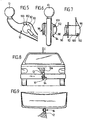
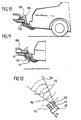
- the detection side 102 of the coupling ball 12 faces is such that an outgoing from the detection side 102 Detection area 104 as shown in Figs. 8, 9 and 10, the coupling ball 12 detected to essential parts, namely preferably such that at least half of the surface the coupling ball 12 can be seen whether on this, as in Fig. 10, a ball coupling 106 of a Trailer attacks and the coupling ball 12 in known Way comprises or whether the coupling ball 12 otherwise applied is, for example, by a shoe 108 or a another object. (Fig. 11)
- the senor 100 comprises a transmitter 110, which in the example, cone-shaped Detection area 104 airborne ultrasonic wave pulse packets 112 while one is also in the Sensor 100 provided detector 114 reflected, returning Ultrasonic wave pulse packets 116 detected.
- a transmitter 110 which in the example, cone-shaped Detection area 104 airborne ultrasonic wave pulse packets 112 while one is also in the Sensor 100 provided detector 114 reflected, returning Ultrasonic wave pulse packets 116 detected.
- the sensor 100 further comprises an evaluation 118, which are generated by evaluation of the detector 114 Signal in relation to the activity of the transmitter 110 capable is to determine whether the coupling ball 12, as in Fig. 8, 9, is free of external influence or whether this the ball coupling 106 or the object 108th Attack, as attacked by a on the coupling ball 12 attacking Object the transit time of the reflected ultrasonic wave pulse packets 116, which impinge on the detector 114, changes.
- the transmitter 118 Due to the changed duration of the reflected Ultrasonic wave pulse packets 116 is the transmitter 118 capable of outputting a detector signal SE, which is the existing or nonexistent effect on the Clutch ball 12 reports.
- a Ultrasonic transducer used to send the Ultraschallwellenimpulscous 112 as a transmitter and to detect the back-reflected ultrasonic wave pulse packets 116 as Detector is operable.
- an ultrasonic wave 112 emitting Transmitter 110 and an ultrasonic waves 116 detecting Detector 114 it is also conceivable infrared radiation with a corresponding transmitter 110 to send out and the infrared radiation with a correspondingly different detector 114 to detect or radar waves and send them to detect.
- the evaluation electronics 118 is, as shown in FIG. 13, connected to a sensor control circuit 120, which the Sensor 100 operates and, for example, a sensor 100 activating signal AK of the transmitter 118 then transmitted when the sensor 100 is to check whether the Clutch ball 12 is acted upon by an object or not.
- the sensor control circuit 120 is capable during defined detection time intervals Z with the signal AK the Sender 100 to activate, so that, for example, during the defined detection time intervals Z of the transmitter 110 the Ultrasonic waves 112 emits.
- the sensor control circuit 120 determines the transmitter 118, based on the signal received from the detector 114, whether the Coupling ball 12 is acted upon by an object or Not. If this is the case, as shown by way of example in FIG. 14, the sensor control circuit 120 always the transmitted from 0 different detector signal SE, if they in turn, with the signal AK activates the sensor 100.
- the sensor control circuit 120 in turn comprises a clock stage 122, which sets time intervals ⁇ t, the between the individual, consecutive, during the Detektionszeitintervals Z existing signal AK are.
- the time intervals ⁇ t are of different lengths adjustable.
- the sensor control circuit 120 If the sensor control circuit 120 has been activated, for example, by means of a start signal S, it enters its active state or mode and in this case the clock generator stage 122 generates the signals AK with time intervals ⁇ t 1 between them, which are the shortest possible.
- the clock stage 122 changes the time intervals ⁇ t to larger values, so that the latter now outputs the signals AK with time intervals ⁇ t 2 between them, these time intervals ⁇ t 2 being greater than the time intervals ⁇ t 1 .
- the clock generator stage 122 again changes the time intervals ⁇ t to even greater values, namely the values ⁇ t 3, and thus transmits the signals AK to the sensor 100 at even greater intervals during a period T 3 .
- the coupling ball 12 is checked very frequently by the sensor 100, while the frequency of the checks of the coupling ball 12 during the period T 2 becomes lower and becomes even lower during the period T 3 .
- the clock stage 122 After elapse of the period T 3 , the clock stage 122 no longer outputs signals AK, and thus the clock stage 122 of the sensor control circuit 120 transitions to its inactive state or inactive mode.
- the sensor control circuit includes 120 also has a memory stage 124, which, the from the evaluation 118 output detector signal SE stores until a re-activation of the sensor 100 is done by means of the signal AK and the transmitter 118 indicates by the signal SE, whether the coupling ball 12 through an object, such as the ball coupling 106, is charged or not.
- This storage stage 124 stores each of the sensor 100 detected impact state until the renewed query by the sensor 100, so that, as shown in Fig. 14, the Memory stage 124 is capable of a trailer presence signal To produce SZ, by means of which at any time t detected can be, whether the coupling ball 12 by a Object is acted upon or not.
- This trailer presence signal SZ is for example from a Control 130 of the hitch interrogated, the thus in is able to decide if at all the ball neck 10 may be swung out of the working position A or Not.
- the controller 130 includes, for example, a start button T, with which a movement of the ball neck 10th between the working position A and the rest position R triggered is. That is, when the button T in the rest position R the ball neck 10 is pressed, there is a pivoting of the ball neck 10 from the rest position R in the working position A, however, the button T is in the working position A is pressed, so pivoting of the ball neck 10 takes place from the working position A to the rest position R.
- a start button T with which a movement of the ball neck 10th between the working position A and the rest position R triggered is. That is, when the button T in the rest position R the ball neck 10 is pressed, there is a pivoting of the ball neck 10 from the rest position R in the working position A, however, the button T is in the working position A is pressed, so pivoting of the ball neck 10 takes place from the working position A to the rest position R.
- the controller 130 transmits the start signal S of the clock stage 122, which then during the period T 1 with short intervals .DELTA.t 1 the signal AK for activating the sensor 100 and at the same time stores the signal SE of the sensor 100, so that the controller 130 has the trailer presence signal SZ indicative of the state of action of the coupling ball 12 (FIG. 19).
- the controller 130 will first drive 58 to Release the fixation of the ball neck 10 in the working position A drive, then again query the status signal SZ and only when it is certain that the coupling ball 12 is not is acted upon by an object, the pivot drive 66th to control the ball neck 10 from the working position A in Towards the rest position R to pivot.
- a Sensor 140 is provided which checks whether a plug 142 a trailer is plugged into the socket 94 (FIG. 13 and 15).
- the senor 140 is a pushbutton 144 or Button formed, and it takes place when plugging the Plug 142 into the socket 94 an actuation of a Tastnase 146 of the key switch 144, which a switching contact 148 closes, which thus in the socket 94th Plug 142 of the controller 130, a trailer presence signal DZ reports.
- the controller 130 in terms of activation the drive 58 or the rotary actuator 66 is blocked
- the controller 130 is in terms of Activation of the drive 58 or the pivot drive 66 blocked.
- the push-button 144 sits in a for this purpose Contact socket 150 of socket 94 and is replaced by a projection 152 of the plug 142 is applied, wherein the projection 152, as shown in Fig. 15, the outer sleeve of Plug 142 may be, but it is also conceivable as a projection to provide an additional pin of the plug 142, which acts on the Tastnase 146.
- the senor 140 not as Actuate pushbutton 144, but as a proximity switch, which plugged into the socket 94 plug 142 detects without contact.
- the senor 140 As shown in Fig. 16, the sensor 140 as a detection circuit 154 designed for trailer-side electrical loads, which thus recognizes whether due to the in the socket 94 inserted plug 142 to the individual electrical Contacts the usual electrical loads, z. B. through the taillights and turn signals, are present.
- the detection circuit 154 generates the trailer presence signal DZ then, if these loads are present, because with it is ensures that not just any plug 142 in the Outlet 94 is plugged in, but the plug 142 actually with the usual electric in a trailer Loads connected.
- the detection circuit 154 is particularly easy realize that these each of the lines 156, the lead to the socket 94, taps and their resistance against Measures the mass then for the typical electrical load in the Trailer must correspond to corresponding resistance.
- the detection circuit 154 is switched to that they already have an existing electrical load between one of the lines 156 and ground the trailer presence signal DZ delivers, so this trailer presence signal also for example with a damaged trailer lamp is delivered.
- the sensor 140 designed as a detection circuit 154 can at any point of supply 158 of the trailer socket 94 be arranged and must therefore not necessarily in the Trailer socket 94 itself be arranged, the arrangement the detection circuit 154 between the individual Lines 156 connected switches for energizing the various lines 156 and the socket 94 arranged have to be.
- the controller 130 switches the sensor control circuit 120 and thus the sensor 100 by means of a switching signal SS at least when the ball neck 10 in the Resting position R or at least near the rest position R, to prevent when entering the rest position R the sensor 100 erroneously an admission of the Coupling ball 12 reports, although this is not the case but only the detection area 104, for example Body parts or other objects on the way to the Rest position detected.
- the sensor control circuit 120 and thus also the sensor 100 are turned on at least then by the switching signal SS, when the ball neck 10 in the working position A stands. But it is also possible, the sensor control circuit 120 already in all positions of the ball neck, which are close to working position A or the between a bottom dead center U of the coupling ball 12, in which this the road 18 comes closest, and the working position A are, so that for example already be recognized when swinging into the working position A. if that is provided for coupling the trailer Ball coupling 106 in the range of movement of Coupling ball 12 comes and the coupling ball 12, for example with this ball coupling piece 106 before reaching the Working position A or in working position A. would.
- the ball neck 10 from the rest position R pivoted into the working position A it takes place at the latest on reaching the working position A by the Start signal S is a start of the sensor control circuit 120 and, since it can be assumed that within a noteworthy attaching a trailer by putting on the trailer Ball coupling piece 106 takes place on the coupling ball 12, a frequent activation of the sensor 100 by means of the Signal AK.
- the ball coupling piece 106 placed If it is found that the ball coupling piece 106 placed is, then stores the memory stage 124 that the patch Ball coupling piece 106 corresponding detection signal SE, so that the controller 130 is always the status signal SZ is reported equal to 1, which documents that a Subject on the coupling ball 12 acts.
- the start signal S is not Mandatory to the signal of the button T or reaching the Working position coupled, but the signal S can, for example also by restarting the motor vehicle or certain driving conditions, that is, for example, a Reversing the motor vehicle, the sensor control circuit 120 are sent to verify a possible To act on the coupling ball 12 to cause.
- the Sensor 100 instead of working with ultrasound, also with Working infrared radiation and thus emit infrared radiation and the back-reflected infrared radiation, in particular which reflected back from the area of the coupling ball 12 Detect infrared radiation.
- the transmitter 110 is thus an infrared transmitter and the detector 114 is an infrared detector.
- the sensor 100 as a radar sensor form the electromagnetic waves in the frequency domain radar sends and receives.
- Such a sensor housing 164 is preferably so place the detection area 104 on the motor vehicle 16 facing surface region of the coupling ball 12th essentially completely check.
- a third embodiment of an inventive Towing device shown in FIGS. 18 and 19, is the Transmitter 110 'of the sensor 100' in an opening of the ball neck 10 used and produced by coupling to the ball neck 10 in the ball neck 10 structure-borne noise with ultrasonic waves 112 ', which propagate in the direction of the coupling ball 12, wherein the coupled system of transmitter 110 ', ball neck 10 and Clutch ball 12 operated in the region of its resonance frequency becomes, thereby amplitude and frequency of the ultrasonic waves of the structure-borne noise, their intensity and / or frequency changes when on the hitch ball the ball coupling 106 is seated or a rest of the object acts.
- the sensor 100 is in a bore 170 in FIG Ball neck 10 is arranged, which from a bottom 172 of the Ball neck 10 coaxially inserted into the coupling ball 12 in this is and for example in front of the coupling ball 12 adjacent constriction 174 ends, so that in the area of Constriction 174 and the coupling ball 12 no weakening of the material.
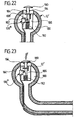
- the coupling ball 12 ' is hollow, wherein in an inner cavity 180 of the coupling ball 12 a Sensor 100 "'is provided with a push-button 182 detected a position of a Tastst Formulaels 184, which, for example is guided in a guide 186 in the cavity 180 and a curved path 188, which depends on the Position of the Tastst Schemeels 184 in different ways the key switch 182 acts, that is, for example, the Pushbutton 182 then acted when the Tastst Congressel 184, as shown in Fig. 23, acted upon by a force F. is, for example, by a on the coupling ball 12 ' mounted ball coupling 106 is generated.
- the tactile plunger 184 has a domed head 190, which approximately to an outer contour of the coupling ball 12 is adapted and by means of a spring 192 from an upper side 194 of the guide 186 is kept lifted, as long as the force F is not effective.
- Effective force F is the Head 190 in the direction of the top 194 of the guide 186 pressed and thus the cam track 188 causes an actuation of the touch sensor 100 "', which then its switching state relative to the non-actuated position of the Tastst formulateels 184th has changed.
- Towing device can account for the sensor control circuit 120, because the push button 100 "always clear and without power can report a switching state, which of the admission or non-loading of the coupling ball 12 ', so that the tact sensor 100 "'directly the Trailer presence signal SZ of the controller 130 available can make.
- the provided with the cavity 180 coupling ball 12 ' is suitable but also for the installation of a coupled to this ultrasonic transducer 110 ', which in the region of the resonant frequency is operated.
- the senor 100 "" includes a key switch 202 a nose 204, which by a cam 206 of a detector lever 208 is operable, which in turn about an axis 210 is pivotally mounted on the ball neck 10.
- the detector lever 208 is formed so that it is in a first position with an end 212 near the coupling ball 12 is, for example, at a small distance from this or is applied to this, so that in this first position of the Detector lever 208 to the coupling ball 12 is not a ball coupling 106 can attack or be put on can.
- end 212 is so far away from the coupling ball 12 movable that the ball coupling 106 can be placed.
- the cam 206 is now formed so that it the push button 202 in standing in the first position detector lever 208 is not actuated while the cam 206 the push button 202 then actuated when the detector lever 208 in its second position, in which the end 212 of the coupling ball 12 is moved away.
- the key switch 202 in the same way as the key switch 182 immediately the trailer presence signal SZ and provides this is available to the controller 130.
- the key switch 202 is near the socket 94 arranged so that in a simple manner via the supply line to Socket 94 also the electrical query of the push-button 202 can take place.
- the key switch 202 in the housing for the outlet immediately and over a between this and the cam 206 effective ram the push button 202 to operate.
Landscapes
- Engineering & Computer Science (AREA)
- Transportation (AREA)
- Mechanical Engineering (AREA)
- Toys (AREA)
- Geophysics And Detection Of Objects (AREA)
- Control Of Position Or Direction (AREA)
- Massaging Devices (AREA)
- Agricultural Machines (AREA)
- Handcart (AREA)
- Control Of Driving Devices And Active Controlling Of Vehicle (AREA)
Description
- Fig. 1
- eine schematische Ansicht von hinten eines ersten Ausführungsbeispiels einer erfindungsgemäßen Anhängevorrichtung;
- Fig. 2
- einen Schnitt längs Linie 2-2 in Fig. 1;
- Fig. 3
- eine Draufsicht auf das erste Ausführungsbeispiel der erfindungsgemäßen Anhängevorrichtung in Richtung des Pfeils A in Fig. 1;
- Fig. 4
- eine schematische vergrößerte Darstellung des Bereichs B in Fig. 3;
- Fig. 5
- eine vergrößerte ausschnittsweise Darstellung des Kugelhalses des ersten Ausführungsbeispiels der erfindungsgemäßen Anhängevorrichtung entsprechend Fig. 2;
- Fig. 6
- eine vergrößerte ausschnittsweise Darstellung des Kugelhalses des ersten Ausführungsbeispiels entsprechend Fig. 1;
- Fig. 7
- eine Darstellung einer in den Kugelhals integrierten Steckdose beim ersten Ausführungsbeispiel;
- Fig. 8
- eine schematische Darstellung eines Erfassungsbereichs eines Sensors beim ersten Ausführungsbeispiel;
- Fig. 9
- eine schematische Darstellung des Erfassungsbereichs des ersten Ausführungsbeispiels bei Blick in Richtung C in Fig. 8;
- Fig. 10
- eine schematische Darstellung des Erfassungsbereichs in der Ansicht gemäß Fig. 2 bei einem an der Kupplungskugel angreifenden Kugelkupplungsstück eines Anhängers;
- Fig. 11
- eine schematische Darstellung einer Einwirkung eines Fremdobjekts, beispielsweise eines Schuhs, auf die Kupplungskugel;
- Fig. 12
- eine schematische Darstellung des Senders gemäß dem ersten Ausführungsbeispiel mit Darstellung des Erfassungsbereichs;
- Fig. 13
- eine schematische Darstellung eines Zusammenwirkens des Sensors mit einer Sensorsteuerschaltung und einer Steuerung für die Anhängevorrichtung;
- Fig. 14
- eine schematische Darstellung von Detektionszeitintervallen, detektierten Signalen und Zustandsintervallen beim ersten Ausführungsbeispiel;
- Fig. 15
- einen Längsschnitt durch eine Steckdose mit Sensor beim ersten Ausführungsbeispiel;
- Fig. 16
- eine Schaltskizze einer Variante des ersten Ausführungsbeispiels mit in einer Versorgung der Steckdose angeordnetem Sensor;
- Fig. 17
- eine schematische Darstellung eines zweiten Ausführungsbeispiels;
- Fig. 18
- eine schematische Darstellung eines Kugelhalses eines dritten Ausführungsbeispiels in der Ansicht gemäß Fig. 5;
- Fig. 19
- eine schematische Darstellung des Kugelhalses des dritten Ausführungsbeispiels mit angreifendem Kugelkupplungsstück;
- Fig. 20
- eine schematische Darstellung eines Kugelhalses eines vierten Ausführungsbeispiels in der Ansicht gemäß Fig. 5;
- Fig. 21
- eine schematische Darstellung des Kugelhalses des vierten Ausführungsbeispiels mit angreifendem Kugelkupplungsstück;
- Fig. 22
- eine ausschnittsweise Darstellung von Kupplungskugel und Kugelhals mit Sensor eines fünften Ausführungsbeispiels im Längsschnitt;
- Fig. 23
- eine schematische Darstellung eines Längsschnitts von Kupplungskugel und Kugelhals des fünften Ausführungsbeispiels mit kraftbeaufschlagtem Sensor;
- Fig. 24
- eine schematische Darstellung eines Kugelhalses eines sechsten Ausführungsbeispiels und
- Fig. 25
- eine Draufsicht auf das sechste Ausführungsbeispiel in Richtung des Pfeils D in Fig. 24.
Claims (40)
- Anhängevorrichtung für Kraftfahrzeuge (16) umfassend einen an einer fahrzeugfesten Aufnahme (30) gehaltenen Kugelhals (10), der an seinem der Aufnahme (30) abgewandten Ende eine Kupplungskugel (12) trägt, eine Fixiereinrichtung (58, 70, 80), welche in einem Fixierzustand den Kugelhals (10) in einer Arbeitsstellung (A) festlegt und welche in einem Lösezustand den Kugelhals (10) für eine Bewegung aus der Arbeitsstellung freigibt, dadurch gekennzeichnet, daß die Anhängevorrichtung mit mindestens einem ein Indiz für die Präsenz eines Anhängers erfassenden Sensor (100, 140) zum Erzeugen eines Anhängerpräsenzsignals versehen ist, daß eine Steuerung (130) vorgesehen ist, mit welcher eine Änderung des Zustands der Fixiereinrichtung (58, 70, 80) blockierbar ist, und daß die Steuerung (130) das Anhängerpräsenzsignal (SZ, DZ) des mindestens einen Sensors (100, 140) abfragt und bei Vorliegen des Anhängerpräsenzsignals (SZ, DZ) eine Änderung des Zustands der Fixiereinrichtung (58, 70, 80) blockiert.
- Anhängevorrichtung nach Anspruch 1, dadurch gekennzeichnet, daß die Steuerung (130) die Anhängerpräsenzsignale mehrerer Sensoren (100, 140) abfragt und bei Vorliegen bereits eines Anhängerpräsenzsignals (SZ, DZ) eine Änderung des Zustands der Fixiereinrichtung (58, 70, 80) blockiert.
- Anhängevorrichtung nach Anspruch 1 oder 2, dadurch gekennzeichnet, daß der Sensor (140) eine Anhängerstromversorgung überwacht und deren Existenz als Indiz für einen angehängten Anhänger wertet.
- Anhängevorrichtung nach Anspruch 3, dadurch gekennzeichnet, daß der Sensor (140) einen in die Steckdose (94) eingesteckten Stecker (142) des Anhängers erkennt.
- Anhängevorrichtung nach Anspruch 4, dadurch gekennzeichnet, daß der Sensor (140) einen Steckerkörper (152) des in die Steckdose (94) eingesteckten Steckers (142) erfaßt.
- Anhängevorrichtung nach Anspruch 5, dadurch gekennzeichnet, daß der den Steckerkörper (152) erfassende Sensor (140) einen Tastschalter (144) umfaßt.
- Anhängevorrichtung nach einem der Ansprüche 3 bis 6, dadurch gekennzeichnet, daß der Sensor (140) als eine elektrische Last des Anhängers erkennende Schaltung (154) ausgebildet ist.
- Anhängevorrichtung nach Anspruch 7, dadurch gekennzeichnet, daß der Sensor (140) in eine Versorgung (158) für die Steckdose (94) integriert ist.
- Anhängevorrichtung nach einem der voranstehenden Ansprüche, dadurch gekennzeichnet, daß der Sensor (100, 100', 100", 100"', 100"") die Kupplungskugel (12) überwacht und ein Angreifen eines Objekts (106, 108) an der Kupplungskugel (12) als Indiz für die Präsenz eines Anhängers wertet.
- Anhängevorrichtung nach einem der voranstehenden Ansprüche, dadurch gekennzeichnet, daß der Sensor (100, 100"") im Bereich der Steckdose (94) angeordnet ist.
- Anhängervorrichtung nach Anspruch 10, dadurch gekennzeichnet, daß der Sensor (100) in die Steckdose (94) integriert ist.
- Anhängevorrichtung nach einem der voranstehenden Ansprüche, dadurch gekennzeichnet, daß der Sensor (100. 100', 100", 100"', 100"") am Kugelhals (10) angeordnet ist.
- Anhängevorrichtung nach Anspruch 12, dadurch gekennzeichnet, daß der Sensor (100) in einem auf den Kugelhals (10) aufgesetzten Gehäuse (134) angeordnet ist.
- Anhängevorrichtung nach Anspruch 12 oder 13, dadurch gekennzeichnet, daß der Sensor (100) im Bereich einer am Kugelhals (10) angeordneten Steckdose (94) angeordnet ist.
- Anhängevorrichtung nach Anspruch 14, dadurch gekennzeichnet, daß der Sensor (100) in die Steckdose (94) integriert ist.
- Anhängevorrichtung nach einem der voranstehenden Ansprüche, dadurch gekennzeichnet, daß der Sensor (100") im Kugelhals (10) angeordnet ist.
- Anhängevorrichtung nach einem der voranstehenden Ansprüche, dadurch gekennzeichnet, daß der Sensor (100, 100"") über einen seitlich des Kugelhalses (10) in Richtung der Kupplungskugel (12) verlaufenden Erfassungsbereich die Kupplungskugel (12) erfaßt.
- Anhängevorrichtung nach einem der Ansprüche 1 bis 16, dadurch gekennzeichnet, daß der Sensor (100', 100") das an der Kupplungskugel (10) angreifende Objekt (106, 108) über den sich zwischen dem Sensor (100', 100") und der Kupplungskugel (12) erstreckenden Abschnitt des Kugelhalses (10) detektiert.
- Anhängevorrichtung nach einem der voranstehenden Ansprüche, dadurch gekennzeichnet, daß der Sensor (100"') in der Kupplungskugel (12) angeordnet ist.
- Anhängevorrichtung nach Anspruch 19, dadurch gekennzeichnet, daß der Sensor (100"') einen einer Seite der Kupplungskugel (12) zugeordnete Erfassungsbereich aufweist.
- Anhängevorrichtung nach einem der voranstehenden Ansprüche, dadurch gekennzeichnet, daß der Sensor (100"', 100"") als durch Einwirkung betätigbarer Sensor arbeitet.
- Anhängevorrichtung nach Anspruch 21, dadurch gekennzeichnet, daß der Sensor (100"') einen Taststößel (184) aufweist, dessen Stellungen erfaßbar sind.
- Anhängevorrichtung nach Anspruch 21 oder 22, dadurch gekennzeichnet, daß der Sensor (100"") ein Detektorhebel (208) aufweist, dessen Stellungen erfaßbar sind.
- Anhängevorrichtung nach einem der Ansprüche 21 bis 23, dadurch gekennzeichnet, daß der Sensor (100"', 100"") einen Schalter umfaßt.
- Anhängevorrichtung nach einem der Ansprüche 1 bis 20, dadurch gekennzeichnet, daß der Sensor (100, 100', 100") berührungslos arbeitet.
- Anhängevorrichtung nach Anspruch 25, dadurch gekennzeichnet, daß der Sensor (100) als optischer Sensor arbeitet.
- Anhängevorrichtung nach Anspruch 25, dadurch gekennzeichnet, daß der Sensor (100) als Radarsensor arbeitet.
- Anhängevorrichtung nach Anspruch 25, dadurch gekennzeichnet, daß der Sensor (100, 100', 100") als Ultraschallsensor arbeitet.
- Anhängevorrichtung nach einem der voranstehenden Ansprüche, dadurch gekennzeichnet, daß der Sensor (100) einen Sender (110) und einen Detektor (114) umfaßt.
- Anhängevorrichtung nach einem der Ansprüche 1 bis 28, dadurch gekennzeichnet, daß der Sensor (100, 100', 100") einen einzigen Wandler (110, 110') umfaßt.
- Anhängevorrichtung nach Anspruch 30, dadurch gekennzeichnet, daß der Wandler (110) als Sender oder Empfänger betreibbar ist.
- Anhängevorrichtung nach Anspruch 30, dadurch gekennzeichnet, daß der Wandler (110') bei einer Resonanzfrequenz von Wandler (110') und Umgebung (10, 12) betreibbar ist.
- Anhängevorrichtung nach einem der voranstehenden Ansprüche, dadurch gekennzeichnet, daß das von dem Sensor (100, 100', 100", 100"', 100"") detektierbare Objekt ein Kugelkupplungsstück (106) ist.
- Anhängevorrichtung nach einem der voranstehenden Ansprüche, dadurch gekennzeichnet, daß dem Sensor (100, 100', 100") eine Sensorsteuerschaltung (120) zugeordnet ist, welche den Sensor (100) während Detektionszeitintervallen (Z) aktiviert, den vom aktivierten Sensor (100) erfaßten Einwirkungszustand (SZ) speichert und anschließend den Sensor (100) deaktiviert.
- Anhängevorrichtung nach Anspruch 34, dadurch gekennzeichnet, daß die Sensorsteuerschaltung (120) den vom aktivierten Sensor (100, 100', 100") erfaßten Einwirkungszustand (SZ) so lange speichert, bis eine erneute Aktivierung des Sensors (100) erfolgt.
- Anhängevorrichtung nach Anspruch 34 oder 35, dadurch gekennzeichnet, daß die Sensorsteuerschaltung (120) nach einem festlegbaren Zeitintervall (Δt) den Sensor (100) selbständig erneut aktiviert und den von diesem erfaßten Einwirkungszustand (SZ) speichert.
- Anhängevorrichtung nach Anspruch 36, dadurch gekennzeichnet, daß die Sensorsteuerschaltung (120) das Zeitintervall ((Δt) nach festlegbaren Zeiträumen (T) verändert.
- Anhängevorrichtung nach Anspruch 36 oder 37, dadurch gekennzeichnet, daß die Sensorsteuerschaltung (120) nach Ablauf eines aktiven Modes in einen inaktiven Mode übergeht, in welchem keine selbständige Aktivierung des Sensors (100, 100', 100") mehr erfolgt.
- Anhängevorrichtung nach einem der Ansprüche 36 bis 38, dadurch gekennzeichnet, daß die Sensorsteuerschaltung (120) das Zeitintervall (Δt) ereignisabhängig festlegt.
- Anhängevorrichtung nach einem der voranstehenden Ansprüche, dadurch gekennzeichnet, daß der Kugelhals (10) mittels eines Antriebs (66) zwischen einer Arbeitsstellung (A) und einer Ruhestellung (R) bewegbar und in der Arbeitsstellung (A) mit der Fixiereinrichtung (58, 70, 80) festlegbar ist, daß eine Steuerung (130) vorgesehen ist, mit welcher die Bewegung und Fixierung steuerbar sind, und daß die Steuerung (130) das Anhängerpräsenzsignal (SZ, DZ) des mindestens einen Sensors (100, 100', 100", 100"', 100"") erfaßt und bei Vorliegen des Anhängerpräsenzsignals (SZ, DZ) ein Lösen der Fixierung in der Arbeitsstellung (A) nicht zuläßt.
Priority Applications (1)
| Application Number | Priority Date | Filing Date | Title |
|---|---|---|---|
| EP04019767A EP1477338B1 (de) | 2000-06-02 | 2000-08-12 | Anhängevorrichtung |
Applications Claiming Priority (2)
| Application Number | Priority Date | Filing Date | Title |
|---|---|---|---|
| DE10027573 | 2000-06-02 | ||
| DE10027573A DE10027573A1 (de) | 2000-06-02 | 2000-06-02 | Anhängevorrichtung |
Related Child Applications (2)
| Application Number | Title | Priority Date | Filing Date |
|---|---|---|---|
| EP04019767A Division EP1477338B1 (de) | 2000-06-02 | 2000-08-12 | Anhängevorrichtung |
| EP04019767.5 Division-Into | 2004-08-20 |
Publications (3)
| Publication Number | Publication Date |
|---|---|
| EP1160104A2 EP1160104A2 (de) | 2001-12-05 |
| EP1160104A3 EP1160104A3 (de) | 2002-04-17 |
| EP1160104B1 true EP1160104B1 (de) | 2004-10-27 |
Family
ID=7644601
Family Applications (3)
| Application Number | Title | Priority Date | Filing Date |
|---|---|---|---|
| EP00117479A Expired - Lifetime EP1160105B2 (de) | 2000-06-02 | 2000-08-12 | Anhängevorrichtung |
| EP00117478A Expired - Lifetime EP1160104B1 (de) | 2000-06-02 | 2000-08-12 | Anhängevorrichtung |
| EP04019767A Expired - Lifetime EP1477338B1 (de) | 2000-06-02 | 2000-08-12 | Anhängevorrichtung |
Family Applications Before (1)
| Application Number | Title | Priority Date | Filing Date |
|---|---|---|---|
| EP00117479A Expired - Lifetime EP1160105B2 (de) | 2000-06-02 | 2000-08-12 | Anhängevorrichtung |
Family Applications After (1)
| Application Number | Title | Priority Date | Filing Date |
|---|---|---|---|
| EP04019767A Expired - Lifetime EP1477338B1 (de) | 2000-06-02 | 2000-08-12 | Anhängevorrichtung |
Country Status (3)
| Country | Link |
|---|---|
| EP (3) | EP1160105B2 (de) |
| AT (3) | ATE349345T1 (de) |
| DE (4) | DE10027573A1 (de) |
Cited By (6)
| Publication number | Priority date | Publication date | Assignee | Title |
|---|---|---|---|---|
| US10670479B2 (en) | 2018-02-27 | 2020-06-02 | Methode Electronics, Inc. | Towing systems and methods using magnetic field sensing |
| US10696109B2 (en) | 2017-03-22 | 2020-06-30 | Methode Electronics Malta Ltd. | Magnetolastic based sensor assembly |
| US11084342B2 (en) | 2018-02-27 | 2021-08-10 | Methode Electronics, Inc. | Towing systems and methods using magnetic field sensing |
| US11135882B2 (en) | 2018-02-27 | 2021-10-05 | Methode Electronics, Inc. | Towing systems and methods using magnetic field sensing |
| US11221262B2 (en) | 2018-02-27 | 2022-01-11 | Methode Electronics, Inc. | Towing systems and methods using magnetic field sensing |
| US11491832B2 (en) | 2018-02-27 | 2022-11-08 | Methode Electronics, Inc. | Towing systems and methods using magnetic field sensing |
Families Citing this family (29)
| Publication number | Priority date | Publication date | Assignee | Title |
|---|---|---|---|---|
| ATE301046T1 (de) * | 2000-10-12 | 2005-08-15 | Oris Fahrzeugteile Riehle H | Anhängevorrichtung |
| DE10104188A1 (de) * | 2001-01-23 | 2002-07-25 | Fac Frank Abels Consult & Tech | Antriebssteuerung für eine Antriebsmotoranordnung einer Anhängerkupplung |
| DE10104180A1 (de) * | 2001-01-23 | 2002-07-25 | Fac Frank Abels Consult & Tech | Anhängerkupplung mit Anhängerkennung |
| DE10144254A1 (de) | 2001-09-03 | 2003-04-03 | Oris Fahrzeugteile Riehle H | Anhängekupplung |
| DE10144822A1 (de) * | 2001-09-12 | 2003-03-27 | Fac Frank Abels Consult & Tech | Warneinrichtung für eine Anhängerkupplung |
| DE20204423U1 (de) * | 2002-03-20 | 2002-07-04 | Erich Jaeger GmbH & Co. KG, 61169 Friedberg | Steckdose für elektrische Steckverbindungen |
| AT412630B (de) | 2003-02-12 | 2005-05-25 | Josef Ing Scharmueller | Kupplungsvorrichtung und verfahren zum schliessen einer kupplungsvorrichtung |
| US7561953B2 (en) | 2005-03-14 | 2009-07-14 | Robert Bosch Gmbh | Method and system of controlling a vehicle in the presence of a disturbance |
| US8740317B2 (en) | 2006-08-11 | 2014-06-03 | Robert Bosch Gmbh | Closed-loop control for trailer sway mitigation |
| DE102008023887A1 (de) | 2008-05-16 | 2009-11-19 | GM Global Technology Operations, Inc., Detroit | Kraftfahrzeug mit einer demontierbaren Anhängerkupplung |
| DE102008034848A1 (de) * | 2008-06-06 | 2009-12-17 | Westfalia-Automotive Gmbh | Anhängekupplung |
| US8838353B2 (en) | 2009-07-24 | 2014-09-16 | Robert Bosch Gmbh | Trailer sway mitigation using measured distance between a trailer and a tow vehicle |
| US8326504B2 (en) | 2009-07-30 | 2012-12-04 | Robert Bosch Gmbh | Holistic control for stabilizing vehicle-trailer swaying |
| DE102009046180A1 (de) * | 2009-10-29 | 2011-05-05 | Scambia Industrial Developments Aktiengesellschaft | Anhängekupplung |
| DE102009046179A1 (de) | 2009-10-29 | 2011-05-05 | Scambia Industrial Developments Aktiengesellschaft | Anhängekupplung |
| DE202011105552U1 (de) * | 2011-05-31 | 2012-09-05 | Westfalia-Automotive Gmbh | Anhängekupplung mit einer Sensorvorrichtung und Sensorvorrichtung dafür |
| DE102011079632A1 (de) * | 2011-07-22 | 2013-01-24 | Zf Friedrichshafen Ag | Anhängerkupplung |
| DE102011052433A1 (de) * | 2011-08-05 | 2013-02-07 | Scambia Holdings Cyprus Ltd. | Steuerungssystem |
| DE102012021352A1 (de) | 2011-11-03 | 2013-05-08 | Westfalia-Automotive Gmbh | Anhängekupplung mit einer Auswerteeinrichtung |
| DE102012008124A1 (de) * | 2012-04-25 | 2013-10-31 | Westfalia-Automotive Gmbh | Kupplungsanordnung für einen Heckträger |
| DE102012105316A1 (de) * | 2012-06-19 | 2013-12-19 | Scambia Holdings Cyprus Ltd. | Anhängekupplung |
| DE102013007726A1 (de) * | 2013-05-07 | 2014-11-13 | Westfalia-Automotive Gmbh | Anhängekupplung mit einer Auswerteeinrichtung |
| PL2862732T5 (pl) | 2013-10-18 | 2022-02-07 | Conwys Ag | Moduł sterujący |
| DE102017121357A1 (de) * | 2017-09-14 | 2019-03-14 | ACPS Automotive GmbH | Anhängekupplung |
| DE202019102152U1 (de) | 2019-04-15 | 2020-07-16 | Ga Actuation Systems Gmbh | Lastenträger |
| DE202019103944U1 (de) * | 2019-04-15 | 2020-07-06 | Ga Actuation Systems Gmbh | Lastenträger |
| DE102023111196B4 (de) * | 2023-05-02 | 2025-02-20 | Audi Aktiengesellschaft | Anhängerkupplungsanordnung für ein Fahrzeug und Verfahren zum Betreiben einer solchen Anhängerkupplungsanordnung |
| DE102023128454A1 (de) * | 2023-10-17 | 2025-04-17 | Brose Fahrzeugteile SE & Co. Kommanditgesellschaft, Coburg | Kupplungsvorrichtung und Verfahren zur Verstellung einer Kupplung |
| US12454221B2 (en) * | 2023-10-18 | 2025-10-28 | Matt Sconce | Tow ball camera assembly |
Family Cites Families (11)
| Publication number | Priority date | Publication date | Assignee | Title |
|---|---|---|---|---|
| US4593264A (en) * | 1983-10-19 | 1986-06-03 | Engle Edgar R | Trailer hitch signaling device |
| US4852901A (en) * | 1987-02-20 | 1989-08-01 | Beasley Donald R | Trailer hitch positioning apparatus |
| US5159312A (en) * | 1991-04-01 | 1992-10-27 | Engle Edgar R | Double switch safety system and signaling device for a trailer hitch coupling |
| US5477207A (en) † | 1993-10-04 | 1995-12-19 | C & M Safety Systems, Inc. | Warning device for a vehicle and trailer coupling system |
| US5434552A (en) * | 1994-01-24 | 1995-07-18 | Ems; Glenn L. | Trailer hitch security system with separate and selectively set loose connection and theft prevention alarms |
| DE4424471C2 (de) † | 1994-07-12 | 1997-03-20 | Daimler Benz Ag | Elektrisches Anhängeranschlußgerät für ein Zugfahrzeug |
| DE19612959A1 (de) * | 1996-04-01 | 1997-10-02 | Oris Fahrzeugteile Riehle H | Anhängekupplung |
| DE19715469C2 (de) * | 1997-04-14 | 1999-11-18 | Oris Fahrzeugteile Riehle H | Anhängekupplung für Kraftfahrzeuge |
| DE19810378A1 (de) * | 1998-03-10 | 1999-09-23 | Oris Fahrzeugteile Riehle H | Anhängekupplung |
| US6481738B1 (en) * | 1998-06-15 | 2002-11-19 | Excalibur Vehicle Accessories (Proprietary) Limited | Connecting device |
| DE19902355A1 (de) * | 1999-01-21 | 2000-08-03 | Oris Fahrzeugteile Riehle H | Anhängekupplung |
-
2000
- 2000-06-02 DE DE10027573A patent/DE10027573A1/de not_active Ceased
- 2000-08-12 DE DE50013912T patent/DE50013912D1/de not_active Expired - Lifetime
- 2000-08-12 EP EP00117479A patent/EP1160105B2/de not_active Expired - Lifetime
- 2000-08-12 AT AT04019767T patent/ATE349345T1/de not_active IP Right Cessation
- 2000-08-12 AT AT00117478T patent/ATE280682T1/de not_active IP Right Cessation
- 2000-08-12 DE DE50013267T patent/DE50013267D1/de not_active Expired - Lifetime
- 2000-08-12 DE DE50008418T patent/DE50008418D1/de not_active Expired - Lifetime
- 2000-08-12 EP EP00117478A patent/EP1160104B1/de not_active Expired - Lifetime
- 2000-08-12 EP EP04019767A patent/EP1477338B1/de not_active Expired - Lifetime
- 2000-08-12 AT AT00117479T patent/ATE334833T1/de not_active IP Right Cessation
Cited By (7)
| Publication number | Priority date | Publication date | Assignee | Title |
|---|---|---|---|---|
| US10696109B2 (en) | 2017-03-22 | 2020-06-30 | Methode Electronics Malta Ltd. | Magnetolastic based sensor assembly |
| US10940726B2 (en) | 2017-03-22 | 2021-03-09 | Methode Electronics Malta Ltd. | Magnetoelastic based sensor assembly |
| US10670479B2 (en) | 2018-02-27 | 2020-06-02 | Methode Electronics, Inc. | Towing systems and methods using magnetic field sensing |
| US11084342B2 (en) | 2018-02-27 | 2021-08-10 | Methode Electronics, Inc. | Towing systems and methods using magnetic field sensing |
| US11135882B2 (en) | 2018-02-27 | 2021-10-05 | Methode Electronics, Inc. | Towing systems and methods using magnetic field sensing |
| US11221262B2 (en) | 2018-02-27 | 2022-01-11 | Methode Electronics, Inc. | Towing systems and methods using magnetic field sensing |
| US11491832B2 (en) | 2018-02-27 | 2022-11-08 | Methode Electronics, Inc. | Towing systems and methods using magnetic field sensing |
Also Published As
| Publication number | Publication date |
|---|---|
| EP1160105B2 (de) | 2013-02-13 |
| DE50013912D1 (de) | 2007-02-08 |
| EP1160104A3 (de) | 2002-04-17 |
| ATE334833T1 (de) | 2006-08-15 |
| DE10027573A1 (de) | 2001-12-06 |
| EP1160105A2 (de) | 2001-12-05 |
| EP1477338A2 (de) | 2004-11-17 |
| EP1477338B1 (de) | 2006-12-27 |
| DE50013267D1 (de) | 2006-09-14 |
| EP1160105A3 (de) | 2002-04-17 |
| DE50008418D1 (de) | 2004-12-02 |
| EP1160104A2 (de) | 2001-12-05 |
| EP1477338A3 (de) | 2005-01-19 |
| EP1160105B1 (de) | 2006-08-02 |
| ATE349345T1 (de) | 2007-01-15 |
| ATE280682T1 (de) | 2004-11-15 |
Similar Documents
| Publication | Publication Date | Title |
|---|---|---|
| EP1160104B1 (de) | Anhängevorrichtung | |
| EP2067692B1 (de) | Bremsscheibenschloss | |
| EP2257460B1 (de) | Sattelkupplung | |
| DE102008018822B4 (de) | Anhängerkupplung für Kraftfahrzeuge, insbesondere Personenkraftfahrzeuge | |
| DE10144822A1 (de) | Warneinrichtung für eine Anhängerkupplung | |
| EP2130698B1 (de) | Anhängekupplung | |
| EP0926024B1 (de) | Schliesssystem, insbesondere für Kraftfahrzeuge | |
| EP1764292B1 (de) | Bremsscheibenschloss | |
| EP2130694B1 (de) | Anhängekupplung | |
| EP2130697B1 (de) | Anhängekupplung | |
| EP1985473B1 (de) | Anhängekupplung mit einer Betätigungseinrichtung | |
| EP2130699B1 (de) | Anhängekupplung | |
| DE202007007331U1 (de) | Anhängerkupplung für Kraftfahrzeuge, insbesondere Personenkraftfahrzeuge | |
| EP4134252A1 (de) | Anhängekupplung | |
| EP0493712B1 (de) | Verriegelungsanlage für eine Tür an einem Kraftfahrzeug | |
| DE202007007313U1 (de) | Anhängerkupplung für Kraftfahrzeuge, insbesondere Personenkraftfahrzeuge | |
| EP2130696B1 (de) | Anhängekupplung mit einem Sensor | |
| EP2130700B1 (de) | Kupplungsarm für eine Anhängekupplung | |
| DE9419272U1 (de) | Alarmverriegelung | |
| DE3006638A1 (de) | Anhaengerkupplung |
Legal Events
| Date | Code | Title | Description |
|---|---|---|---|
| PUAI | Public reference made under article 153(3) epc to a published international application that has entered the european phase |
Free format text: ORIGINAL CODE: 0009012 |
|
| AK | Designated contracting states |
Kind code of ref document: A2 Designated state(s): AT BE DE FR GB NL Kind code of ref document: A2 Designated state(s): AT BE CH CY DE DK ES FI FR GB GR IE IT LI LU MC NL PT SE |
|
| AX | Request for extension of the european patent |
Free format text: AL;LT;LV;MK;RO;SI |
|
| PUAL | Search report despatched |
Free format text: ORIGINAL CODE: 0009013 |
|
| AK | Designated contracting states |
Kind code of ref document: A3 Designated state(s): AT BE CH CY DE DK ES FI FR GB GR IE IT LI LU MC NL PT SE |
|
| AX | Request for extension of the european patent |
Free format text: AL;LT;LV;MK;RO;SI |
|
| 17P | Request for examination filed |
Effective date: 20020903 |
|
| AKX | Designation fees paid |
Free format text: AT BE DE FR GB NL |
|
| GRAP | Despatch of communication of intention to grant a patent |
Free format text: ORIGINAL CODE: EPIDOSNIGR1 |
|
| GRAS | Grant fee paid |
Free format text: ORIGINAL CODE: EPIDOSNIGR3 |
|
| GRAA | (expected) grant |
Free format text: ORIGINAL CODE: 0009210 |
|
| AK | Designated contracting states |
Kind code of ref document: B1 Designated state(s): AT BE DE FR GB NL |
|
| PG25 | Lapsed in a contracting state [announced via postgrant information from national office to epo] |
Ref country code: NL Free format text: LAPSE BECAUSE OF FAILURE TO SUBMIT A TRANSLATION OF THE DESCRIPTION OR TO PAY THE FEE WITHIN THE PRESCRIBED TIME-LIMIT Effective date: 20041027 |
|
| REG | Reference to a national code |
Ref country code: GB Ref legal event code: FG4D Free format text: NOT ENGLISH |
|
| REG | Reference to a national code |
Ref country code: IE Ref legal event code: FG4D Free format text: GERMAN |
|
| REF | Corresponds to: |
Ref document number: 50008418 Country of ref document: DE Date of ref document: 20041202 Kind code of ref document: P |
|
| GBT | Gb: translation of ep patent filed (gb section 77(6)(a)/1977) |
Effective date: 20050126 |
|
| NLV1 | Nl: lapsed or annulled due to failure to fulfill the requirements of art. 29p and 29m of the patents act | ||
| REG | Reference to a national code |
Ref country code: IE Ref legal event code: FD4D |
|
| PLBI | Opposition filed |
Free format text: ORIGINAL CODE: 0009260 |
|
| PG25 | Lapsed in a contracting state [announced via postgrant information from national office to epo] |
Ref country code: AT Free format text: LAPSE BECAUSE OF NON-PAYMENT OF DUE FEES Effective date: 20050812 Ref country code: GB Free format text: LAPSE BECAUSE OF NON-PAYMENT OF DUE FEES Effective date: 20050812 |
|
| PG25 | Lapsed in a contracting state [announced via postgrant information from national office to epo] |
Ref country code: BE Free format text: LAPSE BECAUSE OF NON-PAYMENT OF DUE FEES Effective date: 20050831 |
|
| PLAX | Notice of opposition and request to file observation + time limit sent |
Free format text: ORIGINAL CODE: EPIDOSNOBS2 |
|
| ET | Fr: translation filed | ||
| 26 | Opposition filed |
Opponent name: WESTFALIA-AUTOMOTIVE GMBH & CO. KG Effective date: 20050726 |
|
| PLAF | Information modified related to communication of a notice of opposition and request to file observations + time limit |
Free format text: ORIGINAL CODE: EPIDOSCOBS2 |
|
| PLAF | Information modified related to communication of a notice of opposition and request to file observations + time limit |
Free format text: ORIGINAL CODE: EPIDOSCOBS2 |
|
| GBPC | Gb: european patent ceased through non-payment of renewal fee |
Effective date: 20050812 |
|
| PLBB | Reply of patent proprietor to notice(s) of opposition received |
Free format text: ORIGINAL CODE: EPIDOSNOBS3 |
|
| RAP2 | Party data changed (patent owner data changed or rights of a patent transferred) |
Owner name: SCAMBIA INDUSTRIAL DEVELOPMENTS AKTIENGESELLSCHAFT |
|
| PLBP | Opposition withdrawn |
Free format text: ORIGINAL CODE: 0009264 |
|
| PLBD | Termination of opposition procedure: decision despatched |
Free format text: ORIGINAL CODE: EPIDOSNOPC1 |
|
| BERE | Be: lapsed |
Owner name: *ORIS FAHRZEUGTEILE HANS RIEHLE G.M.B.H. Effective date: 20050831 |
|
| REG | Reference to a national code |
Ref country code: FR Ref legal event code: TP |
|
| PLBM | Termination of opposition procedure: date of legal effect published |
Free format text: ORIGINAL CODE: 0009276 |
|
| STAA | Information on the status of an ep patent application or granted ep patent |
Free format text: STATUS: OPPOSITION PROCEDURE CLOSED |
|
| 27C | Opposition proceedings terminated |
Effective date: 20071223 |
|
| REG | Reference to a national code |
Ref country code: FR Ref legal event code: TP Owner name: SCAMBIA HOLDINGS CYPRUS LIMITED, CY Effective date: 20150105 |
|
| REG | Reference to a national code |
Ref country code: DE Ref legal event code: R082 Ref document number: 50008418 Country of ref document: DE Representative=s name: HOEGER, STELLRECHT & PARTNER PATENTANWAELTE, DE |
|
| REG | Reference to a national code |
Ref country code: DE Ref legal event code: R082 Ref document number: 50008418 Country of ref document: DE Representative=s name: HOEGER, STELLRECHT & PARTNER PATENTANWAELTE, DE Effective date: 20150407 Ref country code: DE Ref legal event code: R081 Ref document number: 50008418 Country of ref document: DE Owner name: SCAMBIA HOLDINGS CYPRUS LTD., CY Free format text: FORMER OWNER: SCAMBIA INDUSTRIAL DEVELOPMENTS AKTIENGESELLSCHAFT, SCHAAN, LI Effective date: 20150407 Ref country code: DE Ref legal event code: R082 Ref document number: 50008418 Country of ref document: DE Representative=s name: HOEGER, STELLRECHT & PARTNER PATENTANWAELTE MB, DE Effective date: 20150407 Ref country code: DE Ref legal event code: R081 Ref document number: 50008418 Country of ref document: DE Owner name: BOSAL ACPS HOLDING 2 B.V., NL Free format text: FORMER OWNER: SCAMBIA INDUSTRIAL DEVELOPMENTS AKTIENGESELLSCHAFT, SCHAAN, LI Effective date: 20150407 |
|
| REG | Reference to a national code |
Ref country code: DE Ref legal event code: R082 Ref document number: 50008418 Country of ref document: DE Representative=s name: HOEGER, STELLRECHT & PARTNER PATENTANWAELTE MB, DE |
|
| REG | Reference to a national code |
Ref country code: FR Ref legal event code: PLFP Year of fee payment: 17 |
|
| REG | Reference to a national code |
Ref country code: FR Ref legal event code: PLFP Year of fee payment: 18 |
|
| REG | Reference to a national code |
Ref country code: DE Ref legal event code: R081 Ref document number: 50008418 Country of ref document: DE Owner name: ACPS AUTOMOTIVE GMBH, DE Free format text: FORMER OWNER: SCAMBIA HOLDINGS CYPRUS LTD., LIMASSOL, CY Ref country code: DE Ref legal event code: R082 Ref document number: 50008418 Country of ref document: DE Representative=s name: HOEGER, STELLRECHT & PARTNER PATENTANWAELTE MB, DE Ref country code: DE Ref legal event code: R081 Ref document number: 50008418 Country of ref document: DE Owner name: BOSAL ACPS HOLDING 2 B.V., NL Free format text: FORMER OWNER: SCAMBIA HOLDINGS CYPRUS LTD., LIMASSOL, CY |
|
| REG | Reference to a national code |
Ref country code: FR Ref legal event code: PLFP Year of fee payment: 19 |
|
| REG | Reference to a national code |
Ref country code: DE Ref legal event code: R082 Ref document number: 50008418 Country of ref document: DE Representative=s name: HOEGER, STELLRECHT & PARTNER PATENTANWAELTE MB, DE Ref country code: DE Ref legal event code: R081 Ref document number: 50008418 Country of ref document: DE Owner name: ACPS AUTOMOTIVE GMBH, DE Free format text: FORMER OWNER: BOSAL ACPS HOLDING 2 B.V., VIANEN, NL |
|
| REG | Reference to a national code |
Ref country code: DE Ref legal event code: R082 Ref document number: 50008418 Country of ref document: DE Representative=s name: HOEGER, STELLRECHT & PARTNER PATENTANWAELTE MB, DE |
|
| PGFP | Annual fee paid to national office [announced via postgrant information from national office to epo] |
Ref country code: FR Payment date: 20190822 Year of fee payment: 20 Ref country code: DE Payment date: 20190822 Year of fee payment: 20 |
|
| REG | Reference to a national code |
Ref country code: DE Ref legal event code: R071 Ref document number: 50008418 Country of ref document: DE |