EP1160140A2 - Hydrauliksystem zum Betätigen von wenigstens zwei Funktionsbereichen in einem Fahrzeug, vorzugsweise zum Lenken und Schalten eines Kraftfahrzeuges - Google Patents
Hydrauliksystem zum Betätigen von wenigstens zwei Funktionsbereichen in einem Fahrzeug, vorzugsweise zum Lenken und Schalten eines Kraftfahrzeuges Download PDFInfo
- Publication number
- EP1160140A2 EP1160140A2 EP20010112317 EP01112317A EP1160140A2 EP 1160140 A2 EP1160140 A2 EP 1160140A2 EP 20010112317 EP20010112317 EP 20010112317 EP 01112317 A EP01112317 A EP 01112317A EP 1160140 A2 EP1160140 A2 EP 1160140A2
- Authority
- EP
- European Patent Office
- Prior art keywords
- brake
- hydraulic system
- valve
- hydraulic
- control unit
- Prior art date
- Legal status (The legal status is an assumption and is not a legal conclusion. Google has not performed a legal analysis and makes no representation as to the accuracy of the status listed.)
- Withdrawn
Links
Images


Classifications
-
- B—PERFORMING OPERATIONS; TRANSPORTING
- B60—VEHICLES IN GENERAL
- B60T—VEHICLE BRAKE CONTROL SYSTEMS OR PARTS THEREOF; BRAKE CONTROL SYSTEMS OR PARTS THEREOF, IN GENERAL; ARRANGEMENT OF BRAKING ELEMENTS ON VEHICLES IN GENERAL; PORTABLE DEVICES FOR PREVENTING UNWANTED MOVEMENT OF VEHICLES; VEHICLE MODIFICATIONS TO FACILITATE COOLING OF BRAKES
- B60T8/00—Arrangements for adjusting wheel-braking force to meet varying vehicular or ground-surface conditions, e.g. limiting or varying distribution of braking force
- B60T8/32—Arrangements for adjusting wheel-braking force to meet varying vehicular or ground-surface conditions, e.g. limiting or varying distribution of braking force responsive to a speed condition, e.g. acceleration or deceleration
- B60T8/321—Arrangements for adjusting wheel-braking force to meet varying vehicular or ground-surface conditions, e.g. limiting or varying distribution of braking force responsive to a speed condition, e.g. acceleration or deceleration deceleration
- B60T8/328—Systems sharing components with other fluid systems onboard the vehicle
-
- B—PERFORMING OPERATIONS; TRANSPORTING
- B60—VEHICLES IN GENERAL
- B60T—VEHICLE BRAKE CONTROL SYSTEMS OR PARTS THEREOF; BRAKE CONTROL SYSTEMS OR PARTS THEREOF, IN GENERAL; ARRANGEMENT OF BRAKING ELEMENTS ON VEHICLES IN GENERAL; PORTABLE DEVICES FOR PREVENTING UNWANTED MOVEMENT OF VEHICLES; VEHICLE MODIFICATIONS TO FACILITATE COOLING OF BRAKES
- B60T13/00—Transmitting braking action from initiating means to ultimate brake actuator with power assistance or drive; Brake systems incorporating such transmitting means, e.g. air-pressure brake systems
- B60T13/10—Transmitting braking action from initiating means to ultimate brake actuator with power assistance or drive; Brake systems incorporating such transmitting means, e.g. air-pressure brake systems with fluid assistance, drive, or release
- B60T13/66—Electrical control in fluid-pressure brake systems
- B60T13/68—Electrical control in fluid-pressure brake systems by electrically-controlled valves
-
- B—PERFORMING OPERATIONS; TRANSPORTING
- B60—VEHICLES IN GENERAL
- B60W—CONJOINT CONTROL OF VEHICLE SUB-UNITS OF DIFFERENT TYPE OR DIFFERENT FUNCTION; CONTROL SYSTEMS SPECIALLY ADAPTED FOR HYBRID VEHICLES; ROAD VEHICLE DRIVE CONTROL SYSTEMS FOR PURPOSES NOT RELATED TO THE CONTROL OF A PARTICULAR SUB-UNIT
- B60W10/00—Conjoint control of vehicle sub-units of different type or different function
- B60W10/10—Conjoint control of vehicle sub-units of different type or different function including control of change-speed gearings
-
- B—PERFORMING OPERATIONS; TRANSPORTING
- B60—VEHICLES IN GENERAL
- B60W—CONJOINT CONTROL OF VEHICLE SUB-UNITS OF DIFFERENT TYPE OR DIFFERENT FUNCTION; CONTROL SYSTEMS SPECIALLY ADAPTED FOR HYBRID VEHICLES; ROAD VEHICLE DRIVE CONTROL SYSTEMS FOR PURPOSES NOT RELATED TO THE CONTROL OF A PARTICULAR SUB-UNIT
- B60W10/00—Conjoint control of vehicle sub-units of different type or different function
- B60W10/18—Conjoint control of vehicle sub-units of different type or different function including control of braking systems
-
- B—PERFORMING OPERATIONS; TRANSPORTING
- B60—VEHICLES IN GENERAL
- B60W—CONJOINT CONTROL OF VEHICLE SUB-UNITS OF DIFFERENT TYPE OR DIFFERENT FUNCTION; CONTROL SYSTEMS SPECIALLY ADAPTED FOR HYBRID VEHICLES; ROAD VEHICLE DRIVE CONTROL SYSTEMS FOR PURPOSES NOT RELATED TO THE CONTROL OF A PARTICULAR SUB-UNIT
- B60W10/00—Conjoint control of vehicle sub-units of different type or different function
- B60W10/20—Conjoint control of vehicle sub-units of different type or different function including control of steering systems
-
- B—PERFORMING OPERATIONS; TRANSPORTING
- B60—VEHICLES IN GENERAL
- B60W—CONJOINT CONTROL OF VEHICLE SUB-UNITS OF DIFFERENT TYPE OR DIFFERENT FUNCTION; CONTROL SYSTEMS SPECIALLY ADAPTED FOR HYBRID VEHICLES; ROAD VEHICLE DRIVE CONTROL SYSTEMS FOR PURPOSES NOT RELATED TO THE CONTROL OF A PARTICULAR SUB-UNIT
- B60W30/00—Purposes of road vehicle drive control systems not related to the control of a particular sub-unit, e.g. of systems using conjoint control of vehicle sub-units
- B60W30/18—Propelling the vehicle
-
- B—PERFORMING OPERATIONS; TRANSPORTING
- B62—LAND VEHICLES FOR TRAVELLING OTHERWISE THAN ON RAILS
- B62D—MOTOR VEHICLES; TRAILERS
- B62D5/00—Power-assisted or power-driven steering
- B62D5/06—Power-assisted or power-driven steering fluid, i.e. using a pressurised fluid for most or all the force required for steering a vehicle
- B62D5/07—Supply of pressurised fluid for steering also supplying other consumers ; control thereof
-
- B—PERFORMING OPERATIONS; TRANSPORTING
- B60—VEHICLES IN GENERAL
- B60W—CONJOINT CONTROL OF VEHICLE SUB-UNITS OF DIFFERENT TYPE OR DIFFERENT FUNCTION; CONTROL SYSTEMS SPECIALLY ADAPTED FOR HYBRID VEHICLES; ROAD VEHICLE DRIVE CONTROL SYSTEMS FOR PURPOSES NOT RELATED TO THE CONTROL OF A PARTICULAR SUB-UNIT
- B60W2710/00—Output or target parameters relating to a particular sub-units
- B60W2710/18—Braking system
-
- Y—GENERAL TAGGING OF NEW TECHNOLOGICAL DEVELOPMENTS; GENERAL TAGGING OF CROSS-SECTIONAL TECHNOLOGIES SPANNING OVER SEVERAL SECTIONS OF THE IPC; TECHNICAL SUBJECTS COVERED BY FORMER USPC CROSS-REFERENCE ART COLLECTIONS [XRACs] AND DIGESTS
- Y10—TECHNICAL SUBJECTS COVERED BY FORMER USPC
- Y10T—TECHNICAL SUBJECTS COVERED BY FORMER US CLASSIFICATION
- Y10T137/00—Fluid handling
- Y10T137/2496—Self-proportioning or correlating systems
- Y10T137/2559—Self-controlled branched flow systems
- Y10T137/265—Plural outflows
-
- Y—GENERAL TAGGING OF NEW TECHNOLOGICAL DEVELOPMENTS; GENERAL TAGGING OF CROSS-SECTIONAL TECHNOLOGIES SPANNING OVER SEVERAL SECTIONS OF THE IPC; TECHNICAL SUBJECTS COVERED BY FORMER USPC CROSS-REFERENCE ART COLLECTIONS [XRACs] AND DIGESTS
- Y10—TECHNICAL SUBJECTS COVERED BY FORMER USPC
- Y10T—TECHNICAL SUBJECTS COVERED BY FORMER US CLASSIFICATION
- Y10T137/00—Fluid handling
- Y10T137/7722—Line condition change responsive valves
- Y10T137/7758—Pilot or servo controlled
- Y10T137/7761—Electrically actuated valve
Definitions
- the invention relates to a hydraulic system for actuating at least two functional areas in one vehicle, preferably for steering and switching a motor vehicle, according to the preamble of claim 1.
- the invention is based, the generic hydraulic system the task to train so that it is optimally used in the vehicle can be.
- the control unit In the hydraulic system according to the invention is to the control unit the braking device of the vehicle connected. This leaves the braking device is actuated directly by the control device, for example via a distance control of the vehicle. If the distance to the vehicle in front is too small, it will take effect the control unit automatically and actuates the braking device, even if the driver of the vehicle has not yet applied the brake pedal has actuated.
- the hydraulic system is used to operate the steering, of the braking system and the gearbox, which is an electronic or electronic-hydraulic gear shift including the Clutch actuation can be.
- the hydraulic system can also for example for actuating a sunroof in the motor vehicle or the like can be used.
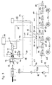
- Fig. 1 shows the hydraulic system with a steering 1, a transmission 2 and a braking device 3 can be operated.
- the Steering 1 has a piston 4 which can be acted upon on both sides and which is in a cylinder 5 is displaceable.
- the piston 4 separates two cylinder spaces 6 and 7 from each other, into each of which a line 8, 9 opens, is supplied via the hydraulic medium.
- the hydraulic medium is by means of a motor 11 and a pump 12 (Fig. 3) conveyed from a tank 13. It is beneficial with one Level sensor 14 provided, which monitors the fill level of the tank 13.
- the hydraulic medium is a via a pressure line 15 Connection valve 16 supplied.
- the hydraulic line coming from the steering 1 8 is also connected to the connecting valve 16.
- a further hydraulic line 17 leads from it via a clutch valve 18 to a clutch 19, which is assigned to the transmission 2.
- the connecting valve 16 ensures that the steering 1, the clutch 19 and the transmission 2 are supplied with hydraulic oil at the same time.
- the connecting valve 16 is designed so that the supply of Hydraulic medium for steering 1 always has priority. This will ensures that the vehicle remains steerable in any case.
- the clutch valve 18 is a pressure sensor 20 and a memory 21 assigned.
- a line 22 connects the clutch valve 18 with the clutch 19.
- the clutch valve 18 via a line 23 connected to a valve block 24 of a gear actuator 25, with which the alleys of the transmission are selected in a known manner and the gears are inserted in the selected alley. It is therefore an automated manual transmission, at the driver of the motor vehicle via a corresponding lever or select the desired gears using the buttons.
- the Gear actuator 25, clutch 19 and clutch valve 18 are on a control unit 26 connected to the functions of this Parts are monitored and controlled.
- the control unit 26 can be operated from the cab 27.
- the Gear 1 shows an example, can in the cab 27, a display 28, a driving switch 29 and a parking lock 30 may be connected to the control unit 26.
- the Gear 2 and clutch 19 are assigned displacement sensors 31, 32, which are connected to the control unit 26 and with which the displacement of pistons can be monitored, which is part of the Gear actuator 25 and the clutch 19 are.
- the gear actuator 25 has Cylinder for aisle selection and aisle movement. Every cylinder A displacement sensor 31 is assigned to each of the gear actuator 25, which works advantageously without contact. Works in the same way the displacement sensor 32 of the coupling 19 advantageously without contact.
- the Clutch valve 18 has a protective function against voltage drop fitted.
- connection valve 16 the clutch valve 18, the pressure sensor 20 and the memory 21 are part of a valve block 33 which for Oil distribution is used.
- the tank is filled 21 monitored by the control unit 26. If the memory is 21 filled, receives the clutch valve 18 from the control unit 26 Open signal. Has the memory 21 of the clutch valve 18th sufficient hydraulic oil, the connection valve 16 via the control unit 26 switched back. Once the clutch is open, it is possible via the control unit 26, the internal combustion engine of the To start the vehicle.
- the hydraulic system comprises the braking device 3, the one Has brake booster 34 in which a piston 35 is displaceable is. It separates two pressure spaces 36, 37 in the brake booster 34 from each other.
- a line opens into the pressure chambers 36, 37 38, 39.
- the line 38 opening into the pressure chamber 36 is connected to a Brake valve 40 and to the line leading to clutch valve 18 17 connected.
- the line opening into the pressure chamber 37 39 is connected to the brake valve 40. It is in turn to the Control unit 26 connected.
- a brake master cylinder is connected downstream of the brake booster 34 41, which in a known manner by one from the brake booster 34 protruding piston rod 42 is actuated. It is by means of a brake pedal 43 which is provided in the motor vehicle and is pivotable against spring force. The swivel path of the Brake pedal 43 is detected by a sensor 44, which is sent to the control unit 26 is connected.
- the brake valve 40 is connected to a tank line 46 via a line 45 connected, which connects the tank 13 to the clutch valve 18.
- the brake valve 40 is provided in the valve block 33.
- the connecting valve 16 advantageously consists of a (not shown) Flow control valve and a switching solenoid valve (not shown).
- a steering wheel 47 of the motor vehicle is not turned, take the piston 4 of the steering 1 the middle position shown in Fig. 1 on.
- the upstream directional valve 10 is also in the middle position switched so that the hydraulic oil is in circulation without pressure.
- the connecting valve 16 ensures that the greater part of the hydraulic oil to the steering 1, while a smaller part on the Line 17, in which one opens towards the clutch valve 18
- Check valve 48 is seated, reaches clutch valve 18.
- Exemplary the connecting valve 16 is designed so that 80% of the hydraulic oil get to steering 1, while 20% to the clutch valve 18 stream.
- the clutch valve 18 is also connected via the line 22 the clutch 19 connected. Via line 23 is to the clutch valve 18 connected to the gear actuator 25 with which the desired Alley of gear 2 selected and the corresponding one Gear is engaged.
- the design of the gear actuator 25 is known and is therefore not explained in more detail.
- the steering 1 takes place in the cylinder 5 Pressure build-up.
- the steering wheel 47 in the illustration 1 rotated to the right, then a steering spindle 49 the piston 4 moves to the right.
- the directional valve 10 is switched so that the hydraulic medium from the tank 13 via the line 8 reaches the pressure chamber 6 of the steering cylinder 5.
- the hydraulic medium in the other pressure chamber 7 flows via line 9, the Directional control valve 10, a tank line 15 connected thereto and the Tank line 46 back to tank 13.
- connection valve 16 the oil supply again divided so that the largest part of the hydraulic medium for steering 1 and a smaller part reaches the clutch valve 18.
- the braking device 3 forms a hydraulic brake booster.
- the braking device is distinguished 3 characterized by their sensitivity. With pressure relief the brake device 3 reacts extremely quickly.
- the hydraulic oil supply the braking device 3 takes place from a pressure accumulator 51 (Fig. 3), in which a predetermined minimum pressure of, for example there is about 40 to about 55 bar.
- a predetermined minimum pressure of, for example there is about 40 to about 55 bar With normal braking is detected by the sensor 44 when the brake pedal 43rd is operated. Since the sensor 44 is connected to the control unit 26 it sends corresponding signals to the brake valve 40, so that it is switched so that the pressure chamber 37 to the tank 13 is relieved.
- you press the brake pedal 43 is over the piston rod 42 of the master cylinder 41 is actuated and the Braking performed. 3 and 4 are explained in more detail.
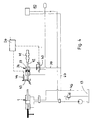
- the hydraulic system according to FIG. 2 differs from the previous one Embodiment only in that the piston 35 in the direction on the master cylinder 41 by at least one compression spring 52 is burdened. Accordingly, only the pressure chamber 37 of the Brake booster 34 via line 39 to brake valve 45 connected. Otherwise, this hydraulic system is of the same design like the exemplary embodiment according to FIG. 1.
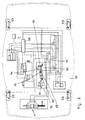
- Fig. 3 shows the hydraulic system in which the braking device 3 with an ABS function is formed.
- Each vehicle wheel 53 are in known manner associated solenoid valves 54, 55 with which the Flow of the hydraulic medium is controlled.
- the solenoid valves 54, 55 are connected in a known manner via hydraulic lines 56, 57 the master brake cylinder 41 of the brake device 3 connected.
- This ABS system makes you independent of the brake pedal movement the vehicle braked reliably in a known manner.
- the solenoid valves 54 each have a hydraulic line 59, 60 which each to the hydraulic line 56, 57 of the master brake cylinder 41 are connected.
- the two hydraulic lines 59, 60 are against each other blocked by a check valve 61, 62, respectively.
- the Pressure chamber 36 of brake cylinder 34 is via hydraulic line 38 connected to the pressure accumulator 51. From the hydraulic line 38 branches off a hydraulic line 63 in the area between the two Check valves 61, 62 open into a hydraulic line 64.
- the solenoid valves 55 are connected to a common hydraulic line 65 connected via a hydraulic line 66 to a tank line 67 is connected. It connects to the tank line 46.
- the solenoid valves 55 are each via a line 68 to the hydraulic line 59 or 60 connected. In line 68 sits in each case a check valve 69 that is directed toward the solenoid valve 55 locks.
- the control unit 26 receives the sensor 44 a signal. It switches the brake valve 40 over, so that the hydraulic medium from the pressure chamber 37 of the brake booster 34 relieved via lines 39, 67, 46 to tank 13 is.
- the master brake cylinder 41 is moved via the piston rod 42 operated.
- the ABS system works in a known manner by adding sensors monitor the peripheral speed of the vehicle wheels 53.
- the hydraulic medium flows via lines 56, 57 to the solenoid valves 54 and via lines 68 to the adjacent solenoid valves 55. From there, the medium flows through the neighboring ones Solenoid valves 55.
- the ABS system works in a known manner.
- the brake is closed in the event of a system failure is, so that the full brake pressure on the brake booster 34 is present. In the event of a system failure, this takes care of the pressure room 36 of the brake booster 34 accommodated compression spring 52 for that the piston rod 42 shifted and thus the master brake cylinder 41 is operated. In an emergency, the brake is automatic actuated without the driver having to press the brake pedal 43. At the Brake booster 34 is full by the force of spring 52 Brake pressure on.
- the vehicle can use the one described with reference to FIG. 3 ABS system are braked to a standstill.
- the Control unit 26 can store different braking programs be, for example, for a full stop, a targeted slow Braking and the like. The control unit 26 thereby ensures that the vehicle is reliable even in the event of a system failure is braked.
- the hydraulic system takes over also the ABS function of the vehicle.
- the brake pressure is on each braked vehicle wheel 53 by the solenoid valves 54, 55 controlled. This allows the conventional ABS system to Control unit, motor, pump and the like are omitted. Since the Brake booster 34 is supplied by the pressure accumulator 51, rapid response and high dynamics are guaranteed. Even if the pump 12 of the hydraulic system fails guaranteed by the memory content of the pressure accumulator 51 that the vehicle braked reliably with brake power assistance becomes.
- Fig. 6 shows a schematic representation of the installation of the hydraulic system into a motor vehicle 70.
- the solenoid valves 54, 55 of the ABS system are combined in a valve block 71, which of the Control unit 26 is controlled.
- the control unit 26 supplies further Signals for an ESP system, distance control and the like. Even an emergency braking function when critical situations are detected is possible. Such critical situations are, for example a blocked road or an obstacle on the road. This Obstacles are recognized due to the distance control, so that it sends corresponding signals to the control unit 26. she sends regardless of the movement of the Brake pedal 43 signals to the valve block 41 of the ABS system, which thereby immediately comes into operation.
- the Brakes of the motor vehicle 70 can thus be actuated independently of the driver be what for example for active distance control and the ESP system is necessary.
- the brake booster function is decoupled from the accelerator pedal position.
- the amplification function is via the sensor 44 on the brake pedal 43 and the proportional directional control valve 40 controlled. It is connected to the control unit 26 so that this valve is instantaneously controlled by the control unit 26 can be.
- the security concept for emergencies due to the still possible manual actuation of the brake without Brake power assistance guaranteed.
- the piston 35 By pressing the brake pedal 43, the piston 35 is displaced in the brake booster 34. With the piston rod 42 carrying the piston 45 the Master brake cylinder 41 without being influenced by the pressure conditions mechanically actuated in the brake booster.
- the brake valve 40 Since the brake valve 40 is controlled by the control unit 26, can the weight by a program stored in the control unit of the vehicle 70 are taken into account in order to achieve an optimal Brake force boost depending on the vehicle speed and get the vehicle mass.
- the brake booster 34 and the master brake cylinder 41 form a brake assistant 72, which has an extremely short response time of, for example, only 5 ms Has. In conventional ABS systems is for the brake booster Negative pressure necessary. Is common with diesel or turbo engines a sufficient vacuum is not available. The hydraulic system described enables the use of a conventional ABS system even with such engines.
Landscapes
- Engineering & Computer Science (AREA)
- Transportation (AREA)
- Mechanical Engineering (AREA)
- Chemical & Material Sciences (AREA)
- Combustion & Propulsion (AREA)
- Automation & Control Theory (AREA)
- Regulating Braking Force (AREA)
- Valves And Accessory Devices For Braking Systems (AREA)
Abstract
Description
- Fig. 1
- in schematischer Darstellung ein erfindungsgemäßes Hydrauliksystem,
- Fig. 2
- in einer Darstellung entsprechend Fig. 1 eine zweite Ausführungsform eines erfindungsgemäßen Hydrauliksystems,
- Fig. 3
- einen Gesamtschaltplan des erfindungsgemäßen Hydrauliksystems,
- Fig. 4
- einen Gesamtschaltplan des erfindungsgemäßen Hydrauliksystems, wenn die Bremse geöffnet ist,
- Fig. 5
- den Gesamtschaltplan gemäß Fig. 4, wenn die Bremse geschlossen ist,
- Fig. 6
- in schematischer Darstellung das erfindungsgemäße Hydrauliksystem in einem Kraftfahrzeug.
Claims (13)
- Hydrauliksystem zum Betätigen von wenigstens zwei Funktionsbereichen in einem Fahrzeug, vorzugsweise zum Lenken und Schalten eines Kraftfahrzeuges, mit wenigstens einem Tank für das Hydraulikmedium, von dem aus das Hydraulikmedium über ein Verteilerventil den beiden Funktionsbereichen zuführbar ist, das an eine Steuereinheit angeschlossen ist und den Strom des Hydraulikmediums zu den beiden Funktionsbereichen so steuert, daß der eine Funktionsbereich Vorrang vor dem anderen Funktionsbereich hat,
dadurch gekennzeichnet, daß an die Steuereinheit (26) eine Bremseinrichtung (3) angeschlossen ist, die einen Bremskraftverstärker (34) und einen Hauptbremszylinder (41) aufweist, von denen der Bremskraftverstärker (34) über ein Bremsventil (40) an die Steuereinheit (26) angeschlossen ist. - Hydrauliksystem nach Anspruch 1,
dadurch gekennzeichnet, daß das Bremsventil (40) ein Proportional-Wegeventil ist. - Hydrauliksystem nach Anspruch 1 oder 2,
dadurch gekennzeichnet, daß der Bremskraftverstärker (34) zwei durch einen Kolben (35) getrennte Druckräume (36, 37) aufweist, von denen der eine Druckraum (37) an das Bremsventil (40) angeschlossen ist. - Hydrauliksystem nach Anspruch 3,
dadurch gekennzeichnet, daß der Kolben (35) auf einer Kolbenstange (42) sitzt, mit der der Hauptbremszylinder (41) betätigbar ist. - Hydrauliksystem nach Anspruch 3 oder 4,
dadurch gekennzeichnet, daß der dem Hauptbremszylinder (41) zugewandte Druckraum (37) des Bremskraftverstärkers (34) mit dem Bremsventil (40) verbunden ist. - Hydrauliksystem nach einem der Ansprüche 3 bis 5,
dadurch gekennzeichnet, daß der andere Druckraum (36) des Bremskraftverstärkers (34) an einen Druckspeicher (51) für das Hydraulikmedium angeschlossen ist. - Hydrauliksystem nach einem der Ansprüche 1 bis 6,
dadurch gekennzeichnet, daß an die Steuereinheit (26) ein Sensor (44) eines Bremspedals (43) angeschlossen ist. - Hydrauliksystem nach einem der Ansprüche 1 bis 7,
dadurch gekennzeichnet, daß an den Hauptbremszylinder (41) ein ABS-System angeschlossen ist. - Hydrauliksystem nach Anspruch 8,
dadurch gekennzeichnet, daß das ABS-System jedem Fahrzeugrad (53) zugeordnete Ventile (54, 55) aufweist. - Hydrauliksystem nach einem der Ansprüche 1 bis 9,
dadurch gekennzeichnet, daß die Steuereinheit (26) eine Abstandsregelung steuert. - Hydrauliksystem nach Anspruch 10,
dadurch gekennzeichnet, daß das ABS-System von der Steuereinheit (26) in Abhängigkeit von Signalen der Abstandsregelung eingeschaltet wird. - Hydrauliksystem, insbesondere nach einem der Ansprüche 1 bis 11,
dadurch gekennzeichnet, daß die Ansteuerung des Bremskraftverstärkers (34) durch die Steuereinheit (26) unabhängig von der Betätigung des Bremspedals (43) erfolgt. - Hydrauliksystem nach einem der Ansprüche 9 bis 12,
dadurch gekennzeichnet, daß das ABS-System an den Druckspeicher (51) angeschlossen ist.
Applications Claiming Priority (2)
| Application Number | Priority Date | Filing Date | Title |
|---|---|---|---|
| DE2000127734 DE10027734A1 (de) | 2000-06-03 | 2000-06-03 | Hydrauliksystem zum Betätigen von wenigstens zwei Funktionsbereichen in einem Fahrzeug,vorzugsweise zum Lenken und Schalten eines Kraftfahrzeuges |
| DE10027734 | 2000-06-03 |
Publications (2)
| Publication Number | Publication Date |
|---|---|
| EP1160140A2 true EP1160140A2 (de) | 2001-12-05 |
| EP1160140A3 EP1160140A3 (de) | 2003-12-17 |
Family
ID=7644708
Family Applications (1)
| Application Number | Title | Priority Date | Filing Date |
|---|---|---|---|
| EP20010112317 Withdrawn EP1160140A3 (de) | 2000-06-03 | 2001-05-19 | Hydrauliksystem zum Betätigen von wenigstens zwei Funktionsbereichen in einem Fahrzeug, vorzugsweise zum Lenken und Schalten eines Kraftfahrzeuges |
Country Status (4)
| Country | Link |
|---|---|
| US (1) | US6474749B2 (de) |
| EP (1) | EP1160140A3 (de) |
| JP (1) | JP2002019591A (de) |
| DE (1) | DE10027734A1 (de) |
Cited By (2)
| Publication number | Priority date | Publication date | Assignee | Title |
|---|---|---|---|---|
| WO2009064394A1 (en) * | 2007-11-13 | 2009-05-22 | Clark Equipment Company | Hydraulic brake system |
| CN102745182A (zh) * | 2012-07-11 | 2012-10-24 | 广东机电职业技术学院 | 离心式液压轻型车辆辅助制动系统 |
Families Citing this family (7)
| Publication number | Priority date | Publication date | Assignee | Title |
|---|---|---|---|---|
| DE19949817A1 (de) * | 1999-10-15 | 2001-04-19 | Bosch Gmbh Robert | Betätigungseinheit für eine Radbremse eines Kraftfahrzeugs |
| US20060196179A1 (en) * | 2005-03-01 | 2006-09-07 | Arun Kesavan | Load-sensing integrated brake and fan hydraulic system |
| US7665742B2 (en) * | 2006-05-12 | 2010-02-23 | Haerr Timothy A | Vehicle hydraulic system |
| DE102006051141A1 (de) * | 2006-10-30 | 2008-05-08 | Siemens Ag | Werkzeugmaschine, Produktionsmaschine und/oder Handlingsmaschine |
| US9067576B2 (en) * | 2011-09-16 | 2015-06-30 | International Truck Intellectual Property Company, Llc | Hydraulic powered park brake system |
| CN111094766B (zh) * | 2017-06-09 | 2023-04-04 | 自由车辆技术有限公司 | 流体控制系统 |
| CN115092248B (zh) * | 2022-07-29 | 2023-10-03 | 中国重汽集团济南动力有限公司 | 制动转向共用油泵变频式调节系统及调节方法 |
Family Cites Families (9)
| Publication number | Priority date | Publication date | Assignee | Title |
|---|---|---|---|---|
| DE1801135A1 (de) * | 1968-10-04 | 1970-04-16 | Maschf Augsburg Nuernberg Ag | Zylinderdeckel fuer fluessigkeitsgekuehlte Brennkraftmaschinen |
| US3640301A (en) * | 1970-06-15 | 1972-02-08 | Ford Motor Co | Hydraulic power supply |
| FR2136857B1 (de) * | 1971-05-07 | 1974-04-05 | Dba | |
| FR2259262B1 (de) * | 1974-01-24 | 1976-11-26 | Poclain Sa | |
| DE3826164A1 (de) * | 1988-08-01 | 1990-02-08 | Rexroth Mannesmann Gmbh | Hydraulik-steuerschaltung fuer ein kraftfahrzeug zur vorrangigen versorgung eines oder mehrerer verbraucher |
| FR2711104B1 (fr) * | 1993-10-12 | 1996-01-05 | Alliedsignal Europ Services | Système de freinage assisté à commande automatique et à réserve contrôlée. |
| GB9416836D0 (en) * | 1994-08-19 | 1994-10-12 | Automotive Products Plc | Fluid pressure supply system |
| US5938297A (en) * | 1996-12-13 | 1999-08-17 | General Motors Corporation | Method and device for brake application |
| DE19834765A1 (de) * | 1998-08-01 | 2000-02-03 | Hydraulik Ring Gmbh | Hydrauliksystem zum Betätigen von wenigstens zwei Funktionsbereichen in einem Fahrzeug |
-
2000
- 2000-06-03 DE DE2000127734 patent/DE10027734A1/de not_active Withdrawn
-
2001
- 2001-05-19 EP EP20010112317 patent/EP1160140A3/de not_active Withdrawn
- 2001-05-28 JP JP2001159219A patent/JP2002019591A/ja active Pending
- 2001-06-04 US US09/874,871 patent/US6474749B2/en not_active Expired - Fee Related
Non-Patent Citations (1)
| Title |
|---|
| None |
Cited By (4)
| Publication number | Priority date | Publication date | Assignee | Title |
|---|---|---|---|---|
| WO2009064394A1 (en) * | 2007-11-13 | 2009-05-22 | Clark Equipment Company | Hydraulic brake system |
| US8360531B2 (en) | 2007-11-13 | 2013-01-29 | Clark Equipment Company | Hydraulic brake system |
| CN102745182A (zh) * | 2012-07-11 | 2012-10-24 | 广东机电职业技术学院 | 离心式液压轻型车辆辅助制动系统 |
| CN102745182B (zh) * | 2012-07-11 | 2015-07-01 | 广东机电职业技术学院 | 离心式液压轻型车辆辅助制动系统 |
Also Published As
| Publication number | Publication date |
|---|---|
| EP1160140A3 (de) | 2003-12-17 |
| JP2002019591A (ja) | 2002-01-23 |
| US6474749B2 (en) | 2002-11-05 |
| US20010048245A1 (en) | 2001-12-06 |
| DE10027734A1 (de) | 2001-12-06 |
Similar Documents
| Publication | Publication Date | Title |
|---|---|---|
| EP0552649B1 (de) | Parkbremssteuersystem | |
| EP0259634B1 (de) | Vorrichtung zur Kupplungsbetätigung | |
| DE19653264B4 (de) | Elektronisch steuerbares Bremssystem für Fahrzeuge, insbesondere Nutzfahrzeuge | |
| EP3473509B1 (de) | Bremsmodul für ein hydraulisch gebremstes zugfahrzeug, welches mit einem pneumatisch gebremsten anhängefahrzeug koppelbar ist | |
| DE19750977B4 (de) | Bremsanlage | |
| WO1996003300A1 (de) | Elektronisch regelbares bremsbetätigungssystem | |
| EP1307373A1 (de) | Elektronisch gesteuerte feststellbremse für ein fahrzeug | |
| DE19920096B4 (de) | Vorrichtung zur Bremslichtansteuerung | |
| EP1743823A1 (de) | Antriebssystem eines Arbeitsfahrzeugs | |
| DE102009050793A1 (de) | Adaptives Bremssystem für Lastanhänger | |
| EP0941188A1 (de) | Elektronisch regelbares bremsbetätigungssystem | |
| DE3636260A1 (de) | Kraftfahrzeug mit zumindest einer permanent angetriebenen achse sowie einer antriebsmaessig zuschaltbaren achse | |
| EP1160140A2 (de) | Hydrauliksystem zum Betätigen von wenigstens zwei Funktionsbereichen in einem Fahrzeug, vorzugsweise zum Lenken und Schalten eines Kraftfahrzeuges | |
| DE102004025402B4 (de) | Verfahren zum Bremsen eines Fahrzeugs mittels einer fluidisch ansteuerbaren Fahrzeugbremsanlage und Fahrzeugbremsanlage | |
| EP1538044B1 (de) | Hydraulische Anhängerbremseinrichtung | |
| DE10319194B3 (de) | Kombinierte hydraulische und elektromechanische Fahrzeugbremsanlage mit einer Bremskraftregeleinrichtung | |
| EP2007611B1 (de) | Verfahren zur regelung des druckes in einem elektronisch gesteuerten bremssystem und elektronisches bremssystem | |
| DE102004017365A1 (de) | Einparkhilfe | |
| DE19855405A1 (de) | Hydraulische Servolenkung für Kraftfahrzeuge | |
| EP1233894B1 (de) | Verfahren zum abbremsen eines fahrzeugs und vorrichtung zur durchführung des verfahrens | |
| EP1121281A1 (de) | Verfahren zum betrieb einer eine schlupfregeleinrichtung aufweisenden fahrzeugbremsanlage | |
| DE4027793A1 (de) | Anordnung zum halten eines fahrzeugs auf einer geneigten fahrbahn | |
| EP3461707A1 (de) | Steuersystem einer hydraulisch betätigten bremseinrichtung | |
| WO2022038075A1 (de) | System und verfahren zum fahrmodus-abhängigen einstellen von fahrzeugeigenschaften eines motorbetriebenen zweirads | |
| WO2021063577A1 (de) | Verfahren zur steuerung einer elektronisch schlupfregelbaren fremdkraftbremsanlage, insbesondere für ein kraftfahrzeug und elektronisch schlupfregelbaren fremdkraftbremsanlage, insbesondere für ein kraftfahrzeug |
Legal Events
| Date | Code | Title | Description |
|---|---|---|---|
| PUAI | Public reference made under article 153(3) epc to a published international application that has entered the european phase |
Free format text: ORIGINAL CODE: 0009012 |
|
| AK | Designated contracting states |
Kind code of ref document: A2 Designated state(s): AT BE CH CY DE DK ES FI FR GB GR IE IT LI LU MC NL PT SE TR |
|
| AX | Request for extension of the european patent |
Free format text: AL;LT;LV;MK;RO;SI |
|
| PUAL | Search report despatched |
Free format text: ORIGINAL CODE: 0009013 |
|
| AK | Designated contracting states |
Kind code of ref document: A3 Designated state(s): AT BE CH CY DE DK ES FI FR GB GR IE IT LI LU MC NL PT SE TR |
|
| AX | Request for extension of the european patent |
Extension state: AL LT LV MK RO SI |
|
| RIC1 | Information provided on ipc code assigned before grant |
Ipc: 7B 60T 17/18 B Ipc: 7B 60T 17/02 B Ipc: 7B 62D 5/07 B Ipc: 7B 60T 13/68 B Ipc: 7B 60T 8/32 B Ipc: 7B 60T 7/04 A |
|
| 17P | Request for examination filed |
Effective date: 20040521 |
|
| 17Q | First examination report despatched |
Effective date: 20040623 |
|
| AKX | Designation fees paid |
Designated state(s): DE ES FR GB IT SE |
|
| GRAP | Despatch of communication of intention to grant a patent |
Free format text: ORIGINAL CODE: EPIDOSNIGR1 |
|
| STAA | Information on the status of an ep patent application or granted ep patent |
Free format text: STATUS: THE APPLICATION IS DEEMED TO BE WITHDRAWN |
|
| 18D | Application deemed to be withdrawn |
Effective date: 20051014 |