EP1160148A2 - Verbindungsanordnung für die Lageranordnung eines Fahrerhauses - Google Patents
Verbindungsanordnung für die Lageranordnung eines Fahrerhauses Download PDFInfo
- Publication number
- EP1160148A2 EP1160148A2 EP01112727A EP01112727A EP1160148A2 EP 1160148 A2 EP1160148 A2 EP 1160148A2 EP 01112727 A EP01112727 A EP 01112727A EP 01112727 A EP01112727 A EP 01112727A EP 1160148 A2 EP1160148 A2 EP 1160148A2
- Authority
- EP
- European Patent Office
- Prior art keywords
- cab
- frame
- under
- mounting rail
- fixed
- Prior art date
- Legal status (The legal status is an assumption and is not a legal conclusion. Google has not performed a legal analysis and makes no representation as to the accuracy of the status listed.)
- Granted
Links
- 239000000470 constituent Substances 0.000 description 10
- 238000003466 welding Methods 0.000 description 8
- 230000008878 coupling Effects 0.000 description 3
- 238000010168 coupling process Methods 0.000 description 3
- 238000005859 coupling reaction Methods 0.000 description 3
- 238000000034 method Methods 0.000 description 2
- 230000004308 accommodation Effects 0.000 description 1
- 238000006073 displacement reaction Methods 0.000 description 1
Images





Classifications
-
- B—PERFORMING OPERATIONS; TRANSPORTING
- B62—LAND VEHICLES FOR TRAVELLING OTHERWISE THAN ON RAILS
- B62D—MOTOR VEHICLES; TRAILERS
- B62D21/00—Understructures, i.e. chassis frame on which a vehicle body may be mounted
- B62D21/15—Understructures, i.e. chassis frame on which a vehicle body may be mounted having impact absorbing means, e.g. a frame designed to permanently or temporarily change shape or dimension upon impact with another body
- B62D21/152—Front or rear frames
-
- B—PERFORMING OPERATIONS; TRANSPORTING
- B62—LAND VEHICLES FOR TRAVELLING OTHERWISE THAN ON RAILS
- B62D—MOTOR VEHICLES; TRAILERS
- B62D33/00—Superstructures for load-carrying vehicles
- B62D33/06—Drivers' cabs
- B62D33/063—Drivers' cabs movable from one position into at least one other position, e.g. tiltable, pivotable about a vertical axis, displaceable from one side of the vehicle to the other
- B62D33/067—Drivers' cabs movable from one position into at least one other position, e.g. tiltable, pivotable about a vertical axis, displaceable from one side of the vehicle to the other tiltable
-
- B—PERFORMING OPERATIONS; TRANSPORTING
- B62—LAND VEHICLES FOR TRAVELLING OTHERWISE THAN ON RAILS
- B62D—MOTOR VEHICLES; TRAILERS
- B62D33/00—Superstructures for load-carrying vehicles
- B62D33/06—Drivers' cabs
- B62D33/063—Drivers' cabs movable from one position into at least one other position, e.g. tiltable, pivotable about a vertical axis, displaceable from one side of the vehicle to the other
- B62D33/067—Drivers' cabs movable from one position into at least one other position, e.g. tiltable, pivotable about a vertical axis, displaceable from one side of the vehicle to the other tiltable
- B62D33/07—Drivers' cabs movable from one position into at least one other position, e.g. tiltable, pivotable about a vertical axis, displaceable from one side of the vehicle to the other tiltable characterised by the device for locking the cab in the tilted or in the driving position
Definitions
- the present invention relates to a joint structure of a cab mounting portion for joining a cab of a forward control vehicle to a chassis frame.
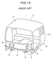
- a cab4 is surrounded by front pillars 9 provided on both right and left sides of a front portion, a front mounting rail 6 provided on an outer surface of the front lower portion, a roof panel 11, a rear panel 12, a side panel 13 and others, and a floor panel 7 is provided on a floor face. Further, cab-under-frames 8 are fixed to the outer surface of the floor panel 7.
- the cab of the forward control vehicle is coupled to a cab mount bracket which is rotatably provided on a chassis frame in a cab mounting portion.
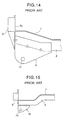
- FIGs. 14 and 15 show an example of the structure of a joint portion for the cab and the chassis frame in the prior art.
- a cab mount bracket 1b has a shape allowing contact with a lower surface or a side surface of the cab-under-frame 8 and a rotation center hole 14 for tilt of the cab 4 is formed thereto. Further, as shown in the drawings, the cab-under-frame 8 is fixed to a outer surface of the floor panel 7, and a front end portion of the cab-under-frame 8 is coupled to the front mounting rail 6 side.
- the cab 4 is supported by fastening the cab-under-frame 8 to the cab mount bracket 1b fixed to the chassis frame, and it is configured so as to sufficiently resist vertical external force applied from a road surface side during normal running.
- an impact load larger than that obtained during normal running acts in the longitudinal direction.
- the structure of the conventional joint portion for the cab and the chassis frame since the cab-under-frame 8 and the cab mount bracket 1b are fastened mainly in the vertical direction, there is a possibility that the structure can not sufficiently resist the impact load in the longitudinal direction.
- the floor structure of a tilt cab in Japanese Utility Model Application Laid-open No. 116277/1981 is a floor constituent member of a tilt cab, in which a front end of a main sill is flange-coupled to a convex shoulder surface of a front cross member constituting the convex shoulder surface on a rear surface side, and a front end of a cab hinge bracket fixed to the main sill is fixed to the convex shoulder surface.
- the rigidity of the coupling portion is insufficient and the coupling rigidity of the cab hinge bracket relative to the main sill is insufficient because the cab hinge bracket is coupled to the convex shoulder surface on the rear surface of the front cross member having the front-open-section. Therefore, the strength against the external force in the longitudinal direction may be possibly insufficient.
- a grill bracket is attached to a front surface of a floor frame which supports a outer surface of a floor panel and to which a cab mounting bracket is fixed, and the grill bracket is fixed to the front grill so that the front grill can function as a strength member.
- this structure cannot sufficiently resist the impact load in the longitudinal direction.
- a joint portion for a cab and a chassis frame has the sufficient shear strength and which can disperse external force across the cab or the chassis frame to reduce the burden of load and which can sufficiently resist an impact load in the longitudinal direction.
- a cab mounting portion structure in which a "inside surface portion of a front mounting rail" provided on a cab front lower side is coupled to a "front end portion upwardly extending a cab-under-frame" fixed to a floor outer surface, a cab mount bracket is also extended upwardly to be coupled to a vehicle front outer portion of the coupling portion, and these three members are integrally fixed to improve the joint strength.
- Figs. 1 to 8 show an embodiment of the present invention.
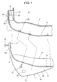
- Fig. 1 is a longitudinal cross section view vertical to a horizontal plane, showing main members of a joint portion 5 for a cab and a chassis frame.
- a front mounting rail 6 having a hat-like cross section is provided on the front lower side of a cab 4 (Fig. 5).
- a front end 7a of a floor panel 7 forming a floor face of the cab 4 uprises to close an opening portion of the front mounting rail 6 and is fixed.
- a cab-under-frame 8 is brought into contact with the outer surface of the floor panel 7 to be fixed, and an upward portion 8a which extends toward the front upper portion of the cab is formed to the front end of the cab-under-frame 8 and fixed to a front vertical surface 18 of the front mounting rail 6.
- Fig. 5 is a perspective view showing the component relationship between front pillars 9, the front mounting rail 6 and the cab-under-frame 8.
- a cab mounting bracket 1 configuring one of constituent parts of the joint portion 5 for the cab and the chassis frame is made up of a bracket bend 2 and a bracket plate 3.
- Fig. 2 is a perspective view of the cab mount bracket 1
- Fig. 3 is a longitudinal cross section view vertical to a horizontal plane showing that the cab-under-frame 8 and the cab mount bracket 1 in Fig. 1 are fastened to constitute the joint portion 5 for the cab and the chassis frame.
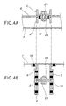
- Fig. 4A is a cross sectional view taken along the line A-A in Fig. 3
- Fig. 4B is a cross sectional view taken along the line B-B in Fig. 3. As shown in Fig.
- the bracket bend 2 is composed of an upper surface portion 15 which has a substantially-C-like cross section and forms a profile matching with a curved surface of an outer surface of the cab-under-frame 8, and a profile portion 16 which forms a largest cross section at a substantially central part by curving the substantially-C-like cross section from the front end toward the rear end.
- a flat portion 17 is formed on the front end side of the upper surface portion 15, and this flat portion 17 comes into contact with the front vertical surface 18 of the front mounting rail 6 as shown in Fig. 3.
- the flat portion 17 and the vicinity thereof form together with a part of the profile portion 16 an upward portion 100 which extends toward the front upper part of the cab along the cab-under-frame 8.
- the bracket plate 3 is formed by a tabular member as shown in Figs. 1, 2 and 3.
- the bracket plate 3 is fixed to each of the both side surfaces of the bracket bend 2 in the state that a curved profile portion 20 is substantially matched with the profile portion 16 of the bracket bend 2.
- a curved portion 19 of the bracket plate 3 is formed so as to largely protrude from the upper surface portion 15 of the bracket bend 2.
- This protruding portion is fixed on the side surface of the cab-under-frame 8 by spot welding or arc welding. As shown in Figs.
- a tilt shaft hole 14 is provided to the cab mount bracket 1, and this hole serves as a bearing portion engaged with a tilt shaft for tilting the cab 4 and simultaneously bearing the load applied to the cab 4.
- Fig. 6 is a perspective view showing the state in which the upward portion 8a at the end of the cab-under-frame 8 is engaged with the cab mount bracket 1, and
- Fig. 7 is an enlarged perspective view showing the cab mount bracket 1 illustrated in Fig. 6.
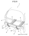
- Fig. 8 is a perspective view showing that constituent parts of the joint portion 5 for the cab and the chassis frame are assembled as a whole. The upward portion 100 of the cab mount bracket 1 is exposed on the outer surface of the front mounting rail 6.
- the bracket bend 2 is provided in such a manner that the upper surface portion 15 is brought into contact with the outer surface of the cab-under-frame 8 and the flat portion 17 on the front end side thereof is brought into contact with the front surface 18 of the front mounting rail 6.
- the bracket bend 2 is coupled and fixed to these portions by mechanical fastening using a bolt 21 and a nut 22 (Figs. 1, 3 and 4) or spot welding or arc welding.
- the bracket plate 3 is fixed on each of the both side surfaces of the cab-under-frame 8 by spot welding or arc welding as illustrated by a welding portion 10 in Fig. 4B.
- the cab mount bracket 1 is stiffly coupled to the front mounting rail 6 and the cab-under-frame 8, and the entire rigidity of the periphery of these members becomes much higher than that of the prior art structure.
- the front mounting rail 6 to which the cab-under-frame 8 or the cab mount bracket 1 according to the present invention is fixed is coupled with the front pillars 9 and 9 at the both ends thereof. Therefore, when external force acts on the cab 4 having the above-described structure in the longitudinal direction, a part of this external force acts on the front surface of the front mounting rail 6.
- the periphery of the front mounting rail 6 is formed so as to have the high rigidity as described above, and the surrounding constituent parts accepts the external force as a whole. Therefore, shear force and the like applied to the individual constituent parts can be greatly reduced.
- the external force which has acted on the front mounting rail 6 side is transmitted to the entire cab 4 through the front pillars 9 and 9, and the external force is dispersed.
- the influence of the external force can be greatly reduced, and it is possible to sufficiently resist the large impact load.
- Figs. 9 to 12 show another embodiment according to the present invention.
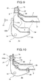
- Fig. 9 is a longitudinal cross section view vertical to a horizontal plane, showing main members of the joint portion 5a for the cab and the chassis frame.
- Fig. 10 is a longitudinal cross section view vertical to a horizontal plane, showing that the cab-under-frame 8 and the cab mount bracket 1a depicted in Fig. 9 are fastened to constitute the joint portion 5a for the cab and the chassis frame.
- the structure of the cab mount bracket 1a, the bracket bend 2a and the bracket plate 3a has the structural influence which is similar to that of the cab mount bracket 1 and others in the above-described embodiment.
- the upward portion 100 of the cab mount bracket 1 is coupled by bringing the flat portion 17 of the bracket bend 2 into contact with the front vertical surface 18 of the front mounting rail 6.
- the upward portion 100a of the cab mount bracket 1a is inserted into the inner side of the front mounting rail 6, and the flat portion 17a is brought into contact with and fixed to the front end 7a of the floor panel 7.
- the front end portion of the cab-under-frame 8 constitutes the upward portion 8b and does not extend to a position at which it is directly joined with the front mounting rail 6.
- Fig. 11 shows the state where the upward portion 8b at the end of the cab-under-frame 8 is engaged with the cab mount bracket 1a.
- Fig. 12 is a perspective view in which the constituent parts of the joint portion 5a for the cab and the chassis frame are assembled as a whole. The front end portion of the cab mount bracket 1a is hidden inside without being exposed on the outer surface of the front mounting rail 6.
- the floor panel 7 is reinforced by the front mounting rail 6 to be formed with the high rigidity, and the entire surrounding constituent members accept the external force. Therefore, as similar to the above-described embodiment, the shear force and the like applied to the individual constituent elements is dispersed and greatly reduced. Further, the external force which has acted from the floor panel 7 through the front mounting rail 6 is transmitted to the entire cab 4 through the front pillars 9 and 9. Therefore, the entire vehicle bears the external force, and the influence of the external force can be greatly reduced to sufficiently resist the large impact load.
- the rigidity of the joint portion for the cab and the chassis frame can be greatly improved, and the external force in the longitudinal direction can be entirely transmitted to the cab and the chassis frame. Further, the influence of the external force can be largely reduced, and it is possible to sufficiently resist the impact load. Moreover, displacement of the cab can be reduced, and an accommodation space can be assured.
Landscapes
- Engineering & Computer Science (AREA)
- Chemical & Material Sciences (AREA)
- Combustion & Propulsion (AREA)
- Transportation (AREA)
- Mechanical Engineering (AREA)
- Body Structure For Vehicles (AREA)
Applications Claiming Priority (2)
| Application Number | Priority Date | Filing Date | Title |
|---|---|---|---|
| JP2000161581A JP2001341666A (ja) | 2000-05-31 | 2000-05-31 | キャブのキャブマウンティング部結合構造 |
| JP2000161581 | 2000-05-31 |
Publications (3)
| Publication Number | Publication Date |
|---|---|
| EP1160148A2 true EP1160148A2 (de) | 2001-12-05 |
| EP1160148A3 EP1160148A3 (de) | 2002-05-02 |
| EP1160148B1 EP1160148B1 (de) | 2003-08-06 |
Family
ID=18665585
Family Applications (1)
| Application Number | Title | Priority Date | Filing Date |
|---|---|---|---|
| EP01112727A Expired - Lifetime EP1160148B1 (de) | 2000-05-31 | 2001-05-25 | Verbindungsanordnung für die Lageranordnung eines Fahrerhauses |
Country Status (5)
| Country | Link |
|---|---|
| US (1) | US6536837B2 (de) |
| EP (1) | EP1160148B1 (de) |
| JP (1) | JP2001341666A (de) |
| CN (1) | CN1333153A (de) |
| DE (1) | DE60100555T2 (de) |
Cited By (1)
| Publication number | Priority date | Publication date | Assignee | Title |
|---|---|---|---|---|
| WO2002094642A1 (de) * | 2001-05-18 | 2002-11-28 | Daimlerchrysler Ag | Tragstruktur eines fahrerhauses für ein nutzfahrzeug |
Families Citing this family (12)
| Publication number | Priority date | Publication date | Assignee | Title |
|---|---|---|---|---|
| DE10343138A1 (de) * | 2003-09-18 | 2005-04-14 | Daimlerchrysler Ag | Längsträger für ein Fahrerhaus sowie Tragstruktur mit einem Längsträger |
| JP4535850B2 (ja) * | 2004-11-18 | 2010-09-01 | ダイハツ工業株式会社 | 自動車の車体側部における補強構造 |
| CN100577495C (zh) * | 2004-12-21 | 2010-01-06 | 日产柴油机车工业株式会社 | 平头型车及其驾驶室安装方法 |
| US8182024B2 (en) * | 2006-05-31 | 2012-05-22 | Caterpillar Inc. | Structure and a system for connecting a machine cab to a supporting frame |
| DE102007041277A1 (de) * | 2007-08-31 | 2009-03-05 | MAN Nutzfahrzeuge Österreich AG | Lastkraftwagen mit speziellem Fahrerhaus |
| JP5679313B2 (ja) * | 2011-03-29 | 2015-03-04 | いすゞ自動車株式会社 | キャブの前端下部構造 |
| CN102514634A (zh) * | 2011-12-09 | 2012-06-27 | 三一重工股份有限公司 | 汽车驾驶室后悬置组件及装置 |
| KR101349536B1 (ko) * | 2011-12-12 | 2014-01-09 | 현대자동차주식회사 | 캡 마운팅장치 |
| DE102012102353A1 (de) | 2012-03-20 | 2013-09-26 | Scania Cv Ab | Tragstruktur |
| KR101637719B1 (ko) * | 2014-11-05 | 2016-07-07 | 현대자동차주식회사 | 트럭의 프런트 캐빈 마운팅 구조 |
| JP6801447B2 (ja) * | 2016-12-27 | 2020-12-16 | いすゞ自動車株式会社 | 車両 |
| CN117262018A (zh) * | 2023-10-24 | 2023-12-22 | 一汽解放汽车有限公司 | 支承结构、车身及车辆 |
Citations (2)
| Publication number | Priority date | Publication date | Assignee | Title |
|---|---|---|---|---|
| JPS56116277A (en) | 1980-02-19 | 1981-09-11 | Sanyo Electric Co Ltd | Manufacture of gas-separating plate for fuel cell |
| JPS61171653A (ja) | 1985-01-25 | 1986-08-02 | Honda Motor Co Ltd | アンチロツク制動装置 |
Family Cites Families (7)
| Publication number | Priority date | Publication date | Assignee | Title |
|---|---|---|---|---|
| JPS58128972A (ja) * | 1982-01-26 | 1983-08-01 | Isuzu Motors Ltd | キヤブのテイルト構造 |
| JPH10203428A (ja) * | 1997-01-20 | 1998-08-04 | Toyota Auto Body Co Ltd | チルト式キャブオーバー型車の車体前部構造 |
| AR008565A1 (es) * | 1997-02-14 | 2000-02-09 | Consorcio G Grupo Dina S A De C V | Una estructura para una cabina aplicable a camiones medianos y tractocamiones |
| JPH10316013A (ja) * | 1997-05-21 | 1998-12-02 | Hino Motors Ltd | トラックのシャシフレーム構造 |
| MXPA97008574A (es) * | 1997-11-07 | 2004-08-23 | Consorcio G Grupo Dina S A De | Estructura mejorada de cabina tipo cab-over paracamion mediano y tractocamion. |
| JPH11301530A (ja) * | 1998-04-15 | 1999-11-02 | Isuzu Motors Ltd | 車両のキャブ補強構造 |
| MXPA01010333A (es) * | 1999-05-26 | 2003-07-21 | Int Truck Intellectual Prop Co | Refuerzo simetrico de tablero de instrumentos. |
-
2000
- 2000-05-31 JP JP2000161581A patent/JP2001341666A/ja active Pending
-
2001
- 2001-05-25 DE DE60100555T patent/DE60100555T2/de not_active Expired - Fee Related
- 2001-05-25 CN CN01118277A patent/CN1333153A/zh active Pending
- 2001-05-25 EP EP01112727A patent/EP1160148B1/de not_active Expired - Lifetime
- 2001-05-30 US US09/870,049 patent/US6536837B2/en not_active Expired - Fee Related
Patent Citations (2)
| Publication number | Priority date | Publication date | Assignee | Title |
|---|---|---|---|---|
| JPS56116277A (en) | 1980-02-19 | 1981-09-11 | Sanyo Electric Co Ltd | Manufacture of gas-separating plate for fuel cell |
| JPS61171653A (ja) | 1985-01-25 | 1986-08-02 | Honda Motor Co Ltd | アンチロツク制動装置 |
Cited By (1)
| Publication number | Priority date | Publication date | Assignee | Title |
|---|---|---|---|---|
| WO2002094642A1 (de) * | 2001-05-18 | 2002-11-28 | Daimlerchrysler Ag | Tragstruktur eines fahrerhauses für ein nutzfahrzeug |
Also Published As
| Publication number | Publication date |
|---|---|
| DE60100555T2 (de) | 2004-06-17 |
| US6536837B2 (en) | 2003-03-25 |
| US20020021026A1 (en) | 2002-02-21 |
| JP2001341666A (ja) | 2001-12-11 |
| EP1160148A3 (de) | 2002-05-02 |
| CN1333153A (zh) | 2002-01-30 |
| EP1160148B1 (de) | 2003-08-06 |
| DE60100555D1 (de) | 2003-09-11 |
Similar Documents
| Publication | Publication Date | Title |
|---|---|---|
| JP3518437B2 (ja) | 車体のサスペンション取付部の構造 | |
| EP2186665B1 (de) | Hecktürstruktur | |
| US6536837B2 (en) | Joint structure of cab mounting portion | |
| JPH0539063A (ja) | 自動車の側部車体構造 | |
| JPH0769147A (ja) | バンパステー構造 | |
| JP2006137208A (ja) | 車両の後部車体構造 | |
| JP2005193843A (ja) | 車両の前部車体構造 | |
| US20240208587A1 (en) | Vehicle rear component | |
| US6971709B2 (en) | Rear side section structure of vehicle | |
| JPH09240510A (ja) | 自動車の車体後部構造 | |
| JPH1016816A (ja) | 車体骨格部材の結合構造 | |
| JP3831622B2 (ja) | 車体の補強構造 | |
| JP2014094636A (ja) | 車両のピラー構造 | |
| JPH06171442A (ja) | バンパーの取付構造 | |
| JP3318736B2 (ja) | バックピラーの上部構造 | |
| JP2002308151A (ja) | キャブオーバー型車のキャブフロア構造 | |
| JP2001301654A (ja) | 自動車の車体側部構造 | |
| JP3183191B2 (ja) | ドアチェックの取付構造 | |
| JP3274079B2 (ja) | 横開き式バックドアの支持構造 | |
| JP2006193001A (ja) | 三角窓補強構造 | |
| JP3327132B2 (ja) | 自動車用ドアの取付構造 | |
| JP3255032B2 (ja) | 自動車用ドアの取付構造 | |
| JPH0649499Y2 (ja) | 車両用ドアおよびステアリングサポートロッドの支持構造 | |
| JP4506268B2 (ja) | 車体のリヤピラー上部構造 | |
| JP2001301645A (ja) | 自動車のフレーム構造 |
Legal Events
| Date | Code | Title | Description |
|---|---|---|---|
| PUAI | Public reference made under article 153(3) epc to a published international application that has entered the european phase |
Free format text: ORIGINAL CODE: 0009012 |
|
| AK | Designated contracting states |
Kind code of ref document: A2 Designated state(s): AT BE CH CY DE DK ES FI FR GB GR IE IT LI LU MC NL PT SE TR Kind code of ref document: A2 Designated state(s): DE FR GB |
|
| AX | Request for extension of the european patent |
Free format text: AL;LT;LV;MK;RO;SI |
|
| PUAL | Search report despatched |
Free format text: ORIGINAL CODE: 0009013 |
|
| AK | Designated contracting states |
Kind code of ref document: A3 Designated state(s): AT BE CH CY DE DK ES FI FR GB GR IE IT LI LU MC NL PT SE TR |
|
| AX | Request for extension of the european patent |
Free format text: AL;LT;LV;MK;RO;SI |
|
| 17P | Request for examination filed |
Effective date: 20020611 |
|
| 17Q | First examination report despatched |
Effective date: 20020802 |
|
| GRAH | Despatch of communication of intention to grant a patent |
Free format text: ORIGINAL CODE: EPIDOS IGRA |
|
| AKX | Designation fees paid |
Free format text: DE FR GB |
|
| GRAH | Despatch of communication of intention to grant a patent |
Free format text: ORIGINAL CODE: EPIDOS IGRA |
|
| GRAA | (expected) grant |
Free format text: ORIGINAL CODE: 0009210 |
|
| AK | Designated contracting states |
Designated state(s): DE FR GB |
|
| REG | Reference to a national code |
Ref country code: GB Ref legal event code: FG4D |
|
| REG | Reference to a national code |
Ref country code: IE Ref legal event code: FG4D |
|
| REF | Corresponds to: |
Ref document number: 60100555 Country of ref document: DE Date of ref document: 20030911 Kind code of ref document: P |
|
| ET | Fr: translation filed | ||
| PLBE | No opposition filed within time limit |
Free format text: ORIGINAL CODE: 0009261 |
|
| STAA | Information on the status of an ep patent application or granted ep patent |
Free format text: STATUS: NO OPPOSITION FILED WITHIN TIME LIMIT |
|
| 26N | No opposition filed |
Effective date: 20040507 |
|
| REG | Reference to a national code |
Ref country code: IE Ref legal event code: MM4A |
|
| PGFP | Annual fee paid to national office [announced via postgrant information from national office to epo] |
Ref country code: FR Payment date: 20060411 Year of fee payment: 6 |
|
| PGFP | Annual fee paid to national office [announced via postgrant information from national office to epo] |
Ref country code: GB Payment date: 20060412 Year of fee payment: 6 |
|
| PGFP | Annual fee paid to national office [announced via postgrant information from national office to epo] |
Ref country code: DE Payment date: 20060419 Year of fee payment: 6 |
|
| GBPC | Gb: european patent ceased through non-payment of renewal fee |
Effective date: 20070525 |
|
| REG | Reference to a national code |
Ref country code: FR Ref legal event code: ST Effective date: 20080131 |
|
| PG25 | Lapsed in a contracting state [announced via postgrant information from national office to epo] |
Ref country code: DE Free format text: LAPSE BECAUSE OF NON-PAYMENT OF DUE FEES Effective date: 20071201 |
|
| PG25 | Lapsed in a contracting state [announced via postgrant information from national office to epo] |
Ref country code: GB Free format text: LAPSE BECAUSE OF NON-PAYMENT OF DUE FEES Effective date: 20070525 |
|
| PG25 | Lapsed in a contracting state [announced via postgrant information from national office to epo] |
Ref country code: FR Free format text: LAPSE BECAUSE OF NON-PAYMENT OF DUE FEES Effective date: 20070531 |