EP1160159B1 - Sicherheitsvorrichtung für einen Hubschrauber - Google Patents
Sicherheitsvorrichtung für einen Hubschrauber Download PDFInfo
- Publication number
- EP1160159B1 EP1160159B1 EP01111443A EP01111443A EP1160159B1 EP 1160159 B1 EP1160159 B1 EP 1160159B1 EP 01111443 A EP01111443 A EP 01111443A EP 01111443 A EP01111443 A EP 01111443A EP 1160159 B1 EP1160159 B1 EP 1160159B1
- Authority
- EP
- European Patent Office
- Prior art keywords
- helicopter
- drive shaft
- air
- parachute
- parachutes
- Prior art date
- Legal status (The legal status is an assumption and is not a legal conclusion. Google has not performed a legal analysis and makes no representation as to the accuracy of the status listed.)
- Expired - Lifetime
Links
- XLYOFNOQVPJJNP-UHFFFAOYSA-N water Substances O XLYOFNOQVPJJNP-UHFFFAOYSA-N 0.000 claims abstract description 14
- 229910000831 Steel Inorganic materials 0.000 claims abstract description 6
- 239000010959 steel Substances 0.000 claims abstract description 6
- 210000001015 abdomen Anatomy 0.000 claims abstract description 4
- 239000002360 explosive Substances 0.000 claims description 6
- 238000007667 floating Methods 0.000 claims description 2
- 238000009434 installation Methods 0.000 claims 1
- 238000013022 venting Methods 0.000 claims 1
- 238000007789 sealing Methods 0.000 abstract description 3
- 238000000034 method Methods 0.000 abstract description 2
- 238000005303 weighing Methods 0.000 abstract description 2
- 238000009423 ventilation Methods 0.000 description 4
- 230000008878 coupling Effects 0.000 description 2
- 238000010168 coupling process Methods 0.000 description 2
- 238000005859 coupling reaction Methods 0.000 description 2
- 239000002184 metal Substances 0.000 description 2
- 229910052751 metal Inorganic materials 0.000 description 2
- OKTJSMMVPCPJKN-UHFFFAOYSA-N Carbon Chemical compound [C] OKTJSMMVPCPJKN-UHFFFAOYSA-N 0.000 description 1
- RYGMFSIKBFXOCR-UHFFFAOYSA-N Copper Chemical group [Cu] RYGMFSIKBFXOCR-UHFFFAOYSA-N 0.000 description 1
- 230000003213 activating effect Effects 0.000 description 1
- 238000004378 air conditioning Methods 0.000 description 1
- 229910052799 carbon Inorganic materials 0.000 description 1
- 238000005474 detonation Methods 0.000 description 1
- 238000009429 electrical wiring Methods 0.000 description 1
- 239000000446 fuel Substances 0.000 description 1
- 239000010687 lubricating oil Substances 0.000 description 1
Images



Classifications
-
- B—PERFORMING OPERATIONS; TRANSPORTING
- B64—AIRCRAFT; AVIATION; COSMONAUTICS
- B64C—AEROPLANES; HELICOPTERS
- B64C27/00—Rotorcraft; Rotors peculiar thereto
-
- B—PERFORMING OPERATIONS; TRANSPORTING
- B64—AIRCRAFT; AVIATION; COSMONAUTICS
- B64C—AEROPLANES; HELICOPTERS
- B64C27/00—Rotorcraft; Rotors peculiar thereto
- B64C27/006—Safety devices
Definitions
- This invention relates to helicopters and more particularly relates to helicopters having emergency provisions for landing safely onto the ground in the event it is disabled in an air accident.
- Helicopter is an air traveling means which meets all transportation requirements. It is a product of much study and constant improvements and it is utilized for a great variety of air operations throughout the world. However, when an accident occurs in which a disabled helicopter weighing several tons including its passengers would imminently fall to the ground resulting in a total fatality. The reason for such disaster is that human is unable to build an infallible helicopter.
- the present invention provides the means which may be incorporated in a helicopter for safely landing it back on the ground when it accidentally becomes disabled People regard the helicopter as a mere half developed product, because it has no provision of resolving such severe problem of safety in the event of an accident when the helicopter is flying high in the sky. If such problem can be resolved, it would fulfill the hope of achieving a safe flying machine which could safeguard the lives of the passengers, so that people would have total confidence in this form of safe transportation.
- the simplest method is by using parachutes to support the helicopter for landing it safely back onto the ground.
- the parachutes would suspend the body of the helicopter in such event to reduce its falling speed.
- the main problem of such concept is that the large propeller of a helicopter covers over a large portion of the helicopter and it is not feasible to deploy a parachute directly over the helicopter since the parachute would readily be severed by the propeller.
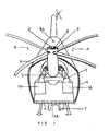
- the helicopter of the present invention is provided with a hollow center1 is its propeller shaft 2.
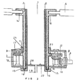
- the drive gears for the shaft 2 are located in a gear box 3 which is filled with lubricating oil.
- the gear box and the rotating shaft 2 are located in a body portion 4 adjacent to the engine 5 of the helicopter.
- the propeller 6 is mounted on the top of the large hollow steel rotating shaft 2.
- a plurality of speed reducing jets 7 are installed at the belly portion of the helicopter, and they are operative for reducing the falling speed to a safe rate when the helicopter is close to the ground so as to obtain a safe landing.
- the duration of the ignition of the jets may be predetermined such that their fuel would be depleted to extinguish their ignition when the helicopter touches the ground so that they would not cause any fire hazard to the helicopter.
- fire extinguishing means 7A is provided, which may be operated to extinguish any residual ignition of the speed reducing jets 7 or due to any other causes after the helicopter has landed on the ground.
- a non-rotatable and not weight bearing tube 8 is provided within the main hollow steel rotating shaft 2
- the hollow center 1 of the tube 8 provides the chamber for housing the main parachute.
- Air ventilation with the outside atmosphere is provided by a telescopic fresh air ventilation tube 8A located at the top of the helicopter body.
- the fresh air ventilation tube 8A may be raised or lowered similar to a periscope of a submarine.
- the ventilation tube 8A may be extended above the waves, when the helicopter lands on a body of water, for conducting fresh air supply to the passengers located inside the helicopter Closure traps are provided at the engine exhaust and air conditioning vent to prevent water from entering into the helicopter through these ports.
- a power drive shaft 9 is coupled to the engine through a high speed gear box having various coupling gears 10, 11, 12, 12R, 13, and 17.
- the gear 13 is mounted on the rotating shaft, and the gear 17 is a horizontal rotating gear mounted on a vertical shaft 18.
- the tube 8 has a closed bottom except for an air opening 1B through which high pressure compressed air may be released into the tube 8 to eject a small parachute which upon deployment will, in turn, pull the main parachute outwards from the helicopter for its deployment.
- the air opening 1B may be eliminated if a very large parachute is required for suspending a heavy helicopter, in such event, the parachute may be located within the helicopter body, and it may be deployed using a small parachute as described above.
- a coupling 14 is provided at the top end of the rotating shaft 2 for mounting the propeller 6.
- the rotation of the propeller is provided by the drive gear 13 which is supported by bearings 16 and 18. Sealing O-rings are provided at circular grooves 15 formed on the propeller shaft 2.
- Chambers 1A are provided for housing the elongated inflatable air bags which may be inflated by high pressure compressed air from air cylinders for maintaining the helicopter afloat when the helicopter falls onto water so as to await for rescue.
- a tubular gasket is provided between the exit door and the door frame The tubular gasket may be inflated either by automatic or manual inflation means to provide a leak-proof joint between the door and the door frame such that no water may leak through the joint into the interior cabin of the helicopter
- Two elongated inflatable air bags are mounted on both sides of the helicopter such that when they are inflated they would maintain the helicopter floating on water in a stable manner.
- the hollow tube 8 for housing the main parachute has a circular fixed bottom 2B, and the parachute is mounted to the helicopter by mounting rings 3B.
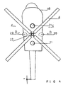
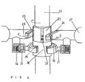
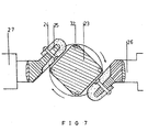
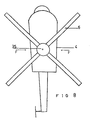
- the propeller 6 of the helicopter may be held stationary at a predetermined position by a braking system as shown in Figures 4, 5, 6 and 7, so as to provide safe spaces required to deploy the parachutes above the helicopter.
- the special braking system is designed to retain and lock the propeller blades at the same predetermined stationary positions over the helicopter body 19.
- Two pairs of auxiliary parachutes 20 and 21 are located on the left and right sides and front and back sides respectively on the top of the helicopter as best shown in Figure 4 and they are positioned at the spaces between the locked blades of the propeller such that these auxiliary parachutes may be deployed safely.
- the propeller of the helicopter is driven by a drive shaft 22 which has an angular portion 23 adapted to engage with angular brake shoes 24 provided on a metal angular support 25 mounted to a sliding rod 26 of an ABS brake system.
- the sliding rod 26 is slidably mounted to a stationary mounting base 27.
- the drive shaft 22 also has a circular brake portion 28 adapted to engage with semi-circular brake shoes 29. The diameter of these brake shoes 29 are equal to that of the circular brake portion 28 of the drive shaft.
- the semi-circular brake shoes 29 are mounted on semi-circular metal arms portion 30 of a spring mounted rod 31. Steel rollers 32 are located between the angular portion 23 on the drive shaft 22; and the sliding rod 26 are fixed extensions which move with the sliding rod 26.
- the rod 31 is biassed by a high strength spring 34 for providing a soft braking action to reduce the rotation of the drive shaft.
- the semi-circular brake shoes 29 will engage the circular brake portion 28 of the drive shaft 22 to cease the rotation of the propeller, and additionally the angular brake shoes 24 will engage with the angular brake portion 23 of the drive shaft 22 so that the propeller blades are always locked at the same predetermined angular positions.
- the unique braking system of the present invention as shown in Figure 6 is operable after the power for rotating the propeller has terminated.
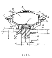
- the main parachute may be installed in an external container 35 provided at the top of the drive shaft 22 and it is rotatable directly with the latter.
- the parachute is housed in an inner box 36 which has a circular top cover and a circular bottom base.
- the inner box 36 is protected by the external container 35.
- the parachute is mounted to the bottom base by a mounting ring 37 and it is located in a chamber 38 formed between the top cover and the bottom base of the inner box 36.
- Rollers 39 are provided between the external container 35 and the top cover and circular base of the inner box 36 such that the external container 35 may rotate relative to the inner box 36.
- Four explosive holding chambers 40 are provided between the top cover and the circular bottom base.
- the explosive in these chambers 40 may be detonated to force open the covers of the inner box and the external container.
- the cover of the external container 35 is normally locked in place with six spring loaded electromagnetic latches 41.
- the electromagnetic latches 41 are unlatched and simultaneously the explosive located in the four chambers 40 are detonated to force open the cover of the external container 35, and since the cover of the inner box 36 is connected to the cover of the external container, it will also be forced open. In this manner, the parachute which is connected to the mounting ring 37 is deployed.
- the electrical power for activating the electromagnetic latches 41 is conducted to the latches through a carbon rod 42 which is in contact with a rotatable copper ring 43 connected to electrical wiring 44 supplying the electrical power to energize the electromagnetic latches and to detonate the explosive in chambers 40.
- the detonation of the explosive causes an annular projection ring 35A to push upwards at a projecting circular flange 36A of the inner box cover
- the steel bottom base 45 of the inner box 36 is coupled to the drive shaft 22 but it is rotatable independently of the latter.
- Figure 10 shows an alternative embodiment for a helicopter in which its body is not wide enough to house the left and right auxiliary parachutes at its top.
- Two horizontally extensible pneumatic arms 20A having an extensible shaft 20B are provided. These pneumatic arms push the connecting cables of the auxiliary parachutes outwards so as to locate the deployed auxiliary parachutes housed at the two sides of the helicopter further outwards of the helicopter body.
Landscapes
- Engineering & Computer Science (AREA)
- Mechanical Engineering (AREA)
- Aviation & Aerospace Engineering (AREA)
- Toys (AREA)
- Emergency Lowering Means (AREA)
- Buildings Adapted To Withstand Abnormal External Influences (AREA)
- Catching Or Destruction (AREA)
Claims (27)
- System zum sicheren Landen eines bei einem Luftunfall abstürzenden Hubschraubersmit wenigstens einem Fallschirm, der an dem Hubschrauber angebracht und für ein Entfalten bei dem Unfall ausgelegt ist,mit Strahltriebwerken für eine Geschwindigkeitsverringerung, die an einem Bodenabschnitt des Hubschraubers angebracht sind und mit dem Fallschirm zur Verringerung der Abstürzgeschwindigkeit des Hubschraubers auf eine sichere Landegeschwindigkeit zusammenwirken,mit an der linken und rechten Unterseite des Hubschraubers angebrachten Aufblaseinrichtungen, die für das Halten des Hubschraubers im Schwimmzustand, wenn der Hubschrauber auf das Wasser fällt, und für eine Stossabfederung ausgelegt sind, wenn der Hubschrauber auf den Boden fällt, undmit einem aufblasbaren Gummischlauch, der an den Verbindungsfugen zwischen Türen und Türrahmen des Hubschraubers vorgesehen und dafür ausgelegt ist, den Leckstrom von Wasser in den Hubschrauber zu verhindern, wenn er auf dem Wasser schwimmt.
- System nach Anspruch 1, bei welchem der Hubschrauber einen Rotor hat, der an einer Antriebswelle aus einem hohlen Stahlrohr mit daran in einem Stück vorgesehenen Antriebszahnrädern angebracht ist.
- System nach Anspruch 2 mit einem stationären Hohlzylinder für die Aufnahme eines mit dem Hubschrauber verbundenen Hauptfallschirms.
- System nach Anspruch 3, bei welchem sich der Hohlzylinder in der Antriebswelle des Rotors befindet.
- System nach Anspruch 2 mit einem Getriebegehäuse mit Zahnrädern, die mit der Antriebswelle gekoppelt und für die Übertragung einer Drehleistung auf die Antriebswelle ausgelegt sind.
- System nach Anspruch 4, bei welchem der Hohlzylinder einen Einlass für Luft mit hohem Druck aufweist, der in einer Bodenplatte ausgebildet ist und so wirkt, dass er Luft mit hohem Druck zum Auswerfen des Fallschirms aus dem Hohlzylinder bereitstellt.
- System nach Anspruch 6 mit einem Verbindungsring, der an der Bodenplatte des Hohlzylinders angeordnet ist, wobei der Fallschirm mit dem Hubschrauber über den Verbindungsring verbunden ist.
- System nach Anspruch 1, bei welchem die Antriebswelle einen im Wesentlichen rechteckigen Winkelabschnitt hat, der mit einem Paar von Winkelbremsbacken zusammenwirkt, die angrenzend an zwei gegenüberliegende Seiten des Winkelabschnitts angeordnet sind, um die Drehung der Antriebswelle in einer vorgegebenen Winkelposition anzuhalten.
- System nach Anspruch 8 mit zwei unter Federwirkung angebrachten halbkreisförmigen Bremsbacken, die angrenzend an die Antriebswelle angeordnet sind und die Rotationsträgheit der Antriebswelle vor der Betätigung der Winkelbremsbacken abbremsen.
- System nach Anspruch 8, bei welchem die Winkelbremsbacken mit dem Winkelabschnitt der Antriebswelle zum Arretieren der Antriebswelle in einer vorgegebenen Winkelposition bei einem Unfall in der Luft sofort zusammenwirken, wenn sich der Hubschrauber anfänglich im Flug befindet.
- System nach Anspruch 10, bei welchem die Winkelbremsbacken und die halbkreisförmigen Bremsbacken mit einem ABS-Bremssystem zusammenwirken.
- System nach Anspruch 10 mit vier Hilfsfallschirmen, die an einem oberen Abschnitt des Hubschraubers angeordnet und in Abständen zwischen den Rotorblättern des Rotors angeordnet sind, wenn die Antriebswelle in der vorgegebenen Winkelposition arretiert ist.
- System nach Anspruch 12 mit einer vorderen Kammer und einer hinteren Kammer, die angrenzend an die Antriebswelle und auf der Oberseite des Hubschraubers angeordnet und für die Aufnahme von zwei Hilfsfallschirmen ausgelegt sind, wobei die vordere Kammer und die hintere Kammer jeweils einen Verbindungsring in ihr zum Verbinden der Hilfsfallschirme mit dem Hubschrauber haben, und mit einer linken Kammer und einer rechten Kammer, die an einem mittleren Rumpfabschnitt des Hubschraubers angeordnet und für die Aufnahme von zwei zusätzlichen Hilfsfallschirmen ausgelegt sind, wobei in der vorderen Kammer, der hinteren Kammer, der linken Kammer und der rechten Kammer Drucklufteinlässe vorgesehen sind, die so wirken, dass Druckluft in alle vier Kammer geleitet wird, um die Hilfsfallschirme und die zusätzlichen Hilfsfallschirme aus allen vier Kammern auszuwerfen.
- System nach Anspruch 1 mit einem am oberen Ende der Antriebswelle angeordneten kastenförmigen Behälter für die Aufnahme des Hauptfallschirms.
- System nach Anspruch 14 mit einem inneren Kasten, der in dem kastenförmigen Behälter angeordnet ist, wobei der mit dem Hubschrauber verbundene Hauptfallschirm in dem inneren Kasten aufgenommen ist und der kastenförmige Behälter mit der Antriebswelle und der innere Kasten bezogen auf den kastenförmigen Behälter und unabhängig von diesem drehbar ist.
- System nach Anspruch 15, bei welchem der Behälter einen oberen Deckel und der innere Kasten ebenfalls einen oberen Deckel aufweist.
- System nach Anspruch 16, bei welchem der obere Deckel des kastenförmigen Behälters normalerweise in einer Schließstellung durch eine Vielzahl von elektromagnetischen Riegeln arretiert ist, in dem kastenförmigen Behälter eine Vielzahl von Explosiveinbauten angeordnet ist, die für ein Entriegeln der elektromagnetischen Riegel zum Öffnen des oberen Deckels des kastenförmigen Behälters zusammenwirken, und der obere Deckel des inneren Kastens mit dem oberen Deckel des kastenförmigen Behälters gekoppelt ist, wodurch das Öffnen des oberen Deckels des kastenförmigen Behälters das gleichzeitige Öffnen des oberen Deckels des inneren Kastens herbeiführt.
- System nach Anspruch 17, bei welchem der innere Kasten ein mit der Antriebswelle gekoppeltes Bodenelement hat, der Hauptfallschirm mit dem Verbindungsring, der sich an dem Bodenelement befindet, durch ein Kabel verbunden ist und das Kabel den Hauptfallschirm mit dem Hubschrauber verbindet, wenn der Hauptfallschirm aus dem Hubschrauber ausgeworfen wird.
- System nach Anspruch 18, bei welchem der innere Kasten auf Rollen gelagert ist, die sich an der Oberseite des oberen Deckels des inneren Kastens bzw. unter dem Bodenelement angeordnet sind, wodurch der innere Kasten bezüglich des kastenförmigen Behälters drehbar ist.
- System nach Anspruch 3 mit einem stationären Zylinder mit geöffneten Boden, der in der hohlen Antriebswelle angeordnet ist und einen Auswerfkanal für den Hauptfallschirm bildet, der sich in dem Hubschrauber befindet.
- System nach Anspruch 1 mit zwei aufblähbaren Luftsäcken, die auf der linken bzw. rechten Seite des Bodenabschnitts des Hubschraubers angeordnet sind.
- System nach Anspruch 1, bei welchem die die Geschwindigkeit reduzierenden Strahltriebwerke an einem Unterseitenabschnitt des Hubschraubers angeordnet sind.
- System nach Anspruch 22 mit Feuerlöscheinrichtungen, die angrenzend an die Strahltriebwerke angeordnet sind.
- System nach Anspruch 8 mit einer Vielzahl von Rollen, die an Kanten des Winkelabschnitts der Antriebswelle angeordnet sind.
- System nach Anspruch 21 mit einem in dem Hubschrauber vorgesehenen Luftschlauch, der am oberen Abschnitt des Hubschraubers angeordnet ist und so wirkt, dass er sich zur Versorgung des Hubschraubers mit Frischluft über die Wellen erstreckt, wenn der Hubschrauber auf das Wasser fällt.
- System nach Anspruch 11 mit zwei Winkelbremsbacken die so wirken, dass sie gegen die gegenüberliegenden Seiten des Winkelabschnitts der Antriebswelle drücken, um die Drehung der Antriebswelle einzustellen.
- System nach Anspruch 13, bei welchem Druckluft mit hohem Druck zum Auswerfen der Hilfsfallschirme aus dem Hubschrauber verwendet wird.
Applications Claiming Priority (2)
| Application Number | Priority Date | Filing Date | Title |
|---|---|---|---|
| US585482 | 2000-06-02 | ||
| US09/585,482 US6382558B1 (en) | 2000-06-02 | 2000-06-02 | Safety system for a helicopter |
Publications (2)
| Publication Number | Publication Date |
|---|---|
| EP1160159A1 EP1160159A1 (de) | 2001-12-05 |
| EP1160159B1 true EP1160159B1 (de) | 2004-07-28 |
Family
ID=24341639
Family Applications (1)
| Application Number | Title | Priority Date | Filing Date |
|---|---|---|---|
| EP01111443A Expired - Lifetime EP1160159B1 (de) | 2000-06-02 | 2001-05-10 | Sicherheitsvorrichtung für einen Hubschrauber |
Country Status (11)
| Country | Link |
|---|---|
| US (2) | US6382558B1 (de) |
| EP (1) | EP1160159B1 (de) |
| JP (1) | JP2003534984A (de) |
| KR (1) | KR20030015249A (de) |
| CN (1) | CN1223490C (de) |
| AT (1) | ATE271996T1 (de) |
| BR (1) | BR0111480A (de) |
| CA (1) | CA2349076C (de) |
| DE (1) | DE60104483T2 (de) |
| RU (1) | RU2284284C2 (de) |
| WO (1) | WO2001092105A1 (de) |
Cited By (1)
| Publication number | Priority date | Publication date | Assignee | Title |
|---|---|---|---|---|
| RU2723564C2 (ru) * | 2015-09-04 | 2020-06-16 | Сафран Хеликоптер Энджинз | Вертолет, оснащенный устройством экстренного обеспечения подъемной силы |
Families Citing this family (29)
| Publication number | Priority date | Publication date | Assignee | Title |
|---|---|---|---|---|
| JP2004017722A (ja) * | 2002-06-13 | 2004-01-22 | Toyota Motor Corp | Vtol機 |
| US7207522B2 (en) * | 2003-08-15 | 2007-04-24 | Apical Industries, Inc. | Safety device trigger for activating a safety device |
| FR2895368B1 (fr) * | 2005-12-27 | 2009-07-03 | Eurocopter France | Atterrisseur de giravion a patins et giravion comportant un tel atterrisseur |
| US8011614B2 (en) | 2007-04-10 | 2011-09-06 | Bird Stanley W | Bird vortex flying machine |
| US8061656B1 (en) | 2009-09-22 | 2011-11-22 | The United States Of America As Represented By The Secretary Of The Navy | Hinge apparatus with an actuatable assembly |
| DE102010010453A1 (de) * | 2010-03-02 | 2012-05-16 | Helmut Rind | Feststehende, hohle Rotorkopfachse mit einem Rotorkopf in zwei Varianten und integrierter Gesamtrettungsgerätaufnahme, für Tragschrauber |
| DE102010012071B4 (de) * | 2010-03-19 | 2013-04-04 | Airbus Operations Gmbh | Verfahren und System zur Steuerung einer Flugzeugkomponente bei einer Wasserlandung |
| RU2458822C1 (ru) * | 2011-05-18 | 2012-08-20 | Пётр Иванович Дуров | Аппарат вертикального взлета и посадки |
| EP2530010B1 (de) * | 2011-06-02 | 2013-09-18 | Bell Helicopter Textron Inc. | Integral versteiftes Panel |
| EP2570348A1 (de) * | 2011-09-19 | 2013-03-20 | Piergiovanni Marega | Befestigung für einen ballistischen Rettungsfallschirm an einem Helikopter |
| CN102431645A (zh) * | 2011-12-06 | 2012-05-02 | 李新民 | 一种防坠毁单人直升机 |
| IL229068A (en) * | 2013-10-24 | 2016-06-30 | Amir Tsaliah | Apparatus and method for rapid deployment of a parachute |
| CN104029813A (zh) * | 2014-06-04 | 2014-09-10 | 深圳市万博鑫科技有限公司 | 航空两栖运输机 |
| CN104670502A (zh) * | 2015-02-09 | 2015-06-03 | 武汉天降科技有限公司 | 一种直升飞机空中停车安全组合软着陆设备及软着陆方法 |
| US10293948B2 (en) * | 2016-10-28 | 2019-05-21 | Kitty Hawk Corporation | Distributed parachute system |
| US10518888B2 (en) * | 2016-11-21 | 2019-12-31 | Kitty Hawk Corporation | Cinched parachute |
| RU2652873C1 (ru) * | 2016-12-09 | 2018-05-03 | Акционерное общество "Московский вертолетный завод им. М.Л. Миля" | Система управления тормозом несущего винта |
| CN106741905B (zh) * | 2017-02-09 | 2019-01-08 | 黄少斌 | 一种水上乐园专用的直升式载人飞行器模型 |
| US11008114B2 (en) * | 2017-09-07 | 2021-05-18 | The Boeing Company | Expandable energy absorbing fluid bladder systems and methods |
| CN107572341A (zh) * | 2017-10-11 | 2018-01-12 | 中国航天科技集团公司川南机械厂 | 一种电梯安全着陆系统及方法 |
| CN108678983A (zh) * | 2018-07-18 | 2018-10-19 | 南昌启迈科技有限公司 | 一种遥控电风扇 |
| CN108891593A (zh) * | 2018-09-03 | 2018-11-27 | 天津曙光天成科技有限公司 | 一种旋翼头安装结构及无人直升机 |
| RU2698141C1 (ru) * | 2018-11-21 | 2019-08-22 | Николай Борисович Болотин | Вертолет |
| NL1043177B1 (en) * | 2019-03-04 | 2020-09-17 | Pal V Ip B V | Vertical Take Off and Landing Vehicle |
| EP4031449A4 (de) | 2019-09-20 | 2024-01-10 | Parazero Technologies Ltd. | Schadensminderung für ein luftfahrzeug mit entfaltbarem fallschirm |
| US11344757B2 (en) | 2020-07-10 | 2022-05-31 | Lockheed Martin Corporation | Automatic main engine fire bottle discharge feature—dual channel design |
| IT202200006902A1 (it) * | 2022-04-07 | 2023-10-07 | Spa Curti Costruzioni Meccaniche | Velivolo ad ala rotante |
| KR102549903B1 (ko) * | 2022-06-02 | 2023-06-29 | 김종환 | 비행체용 낙하산 배출장치 |
| CN116105780B (zh) * | 2023-04-07 | 2023-06-30 | 江苏巨数智能科技有限公司 | 一种具有气动调节系统的抛弃型传感器 |
Family Cites Families (20)
| Publication number | Priority date | Publication date | Assignee | Title |
|---|---|---|---|---|
| US1823799A (en) * | 1930-01-28 | 1931-09-15 | Friedrich Louis | Safety attachment for aircraft |
| US2560665A (en) * | 1946-02-25 | 1951-07-17 | Boeing Co | Door seal for pressurized aircraft |
| US2653779A (en) * | 1951-08-06 | 1953-09-29 | Loren R Terry | Aircraft having reversible jetpropelled rotor blade |
| US2812147A (en) * | 1954-10-15 | 1957-11-05 | Vincent R Trabucco | Helicopter parachute attaching structure |
| US3004737A (en) * | 1957-10-25 | 1961-10-17 | Garrett Corp | Retractable buoyant supporting means for vehicles |
| US3138348A (en) * | 1961-05-15 | 1964-06-23 | Stahmer Bernhardt | Helicopter mounted parachute |
| US3384327A (en) * | 1963-08-27 | 1968-05-21 | Steven Postelson Apostolescu | Flying platform-automobile-boat and air suspension car combination |
| FR1383688A (fr) * | 1964-03-06 | 1964-12-24 | Westland Aircraft Ltd | Flotteurs pour hélicoptère |
| US3377037A (en) * | 1966-10-05 | 1968-04-09 | Edward P Remington | Aircraft emergency ejection arrangement |
| US3745707A (en) * | 1971-08-18 | 1973-07-17 | T Herr | Sliding door construction utilizing an inflatable seal |
| GB1551523A (en) * | 1976-04-30 | 1979-08-30 | American Safety Equip | Float assembly |
| US4167258A (en) * | 1978-03-24 | 1979-09-11 | Lockheed Corporation | Aft cargo door for aircraft |
| US4298177A (en) * | 1979-11-09 | 1981-11-03 | Berlongieri John J | Aircraft safety apparatus |
| GB2133365A (en) * | 1982-12-01 | 1984-07-25 | Egon Spitzer | Improvements in or relating to helicopters |
| US4676457A (en) * | 1984-06-21 | 1987-06-30 | Allen Sebree J | Aircraft emergency landing system |
| DE3425890A1 (de) * | 1984-07-13 | 1986-01-23 | Blohm + Voss Ag, 2000 Hamburg | Schiffstuer- oder -lukenanordnung |
| US4824188A (en) * | 1988-01-21 | 1989-04-25 | Hughes Aircraft Company | Modulation arrangement for anti-lock brake system |
| CA2176073A1 (en) * | 1995-06-26 | 1996-12-27 | Henry Hung Lai Chung | Construction toy support base |
| US5823458A (en) * | 1997-04-18 | 1998-10-20 | Jin Fong Hydrauli Company | Cable spool with a damping brake |
| US6095251A (en) * | 1997-07-22 | 2000-08-01 | Primex Technologies, Inc. | Dual stage fire extinguisher |
-
2000
- 2000-06-02 US US09/585,482 patent/US6382558B1/en not_active Expired - Fee Related
-
2001
- 2001-05-10 DE DE60104483T patent/DE60104483T2/de not_active Expired - Fee Related
- 2001-05-10 EP EP01111443A patent/EP1160159B1/de not_active Expired - Lifetime
- 2001-05-10 AT AT01111443T patent/ATE271996T1/de not_active IP Right Cessation
- 2001-05-28 BR BR0111480-8A patent/BR0111480A/pt active Search and Examination
- 2001-05-28 WO PCT/CA2001/000750 patent/WO2001092105A1/en not_active Ceased
- 2001-05-28 JP JP2001588088A patent/JP2003534984A/ja active Pending
- 2001-05-28 KR KR1020027015585A patent/KR20030015249A/ko not_active Withdrawn
- 2001-05-28 RU RU2002134449/11A patent/RU2284284C2/ru not_active IP Right Cessation
- 2001-05-30 CA CA002349076A patent/CA2349076C/en not_active Expired - Fee Related
- 2001-06-01 CN CNB011208465A patent/CN1223490C/zh not_active Expired - Fee Related
- 2001-08-21 US US09/947,037 patent/US6390413B1/en not_active Expired - Fee Related
Cited By (1)
| Publication number | Priority date | Publication date | Assignee | Title |
|---|---|---|---|---|
| RU2723564C2 (ru) * | 2015-09-04 | 2020-06-16 | Сафран Хеликоптер Энджинз | Вертолет, оснащенный устройством экстренного обеспечения подъемной силы |
Also Published As
| Publication number | Publication date |
|---|---|
| CA2349076A1 (en) | 2001-12-02 |
| CN1223490C (zh) | 2005-10-19 |
| DE60104483T2 (de) | 2005-07-28 |
| RU2284284C2 (ru) | 2006-09-27 |
| US20020030136A1 (en) | 2002-03-14 |
| CA2349076C (en) | 2005-07-05 |
| EP1160159A1 (de) | 2001-12-05 |
| DE60104483D1 (de) | 2004-09-02 |
| US6390413B1 (en) | 2002-05-21 |
| JP2003534984A (ja) | 2003-11-25 |
| KR20030015249A (ko) | 2003-02-20 |
| ATE271996T1 (de) | 2004-08-15 |
| BR0111480A (pt) | 2003-06-10 |
| US6382558B1 (en) | 2002-05-07 |
| CN1326888A (zh) | 2001-12-19 |
| RU2002134449A (ru) | 2004-06-20 |
| WO2001092105A1 (en) | 2001-12-06 |
Similar Documents
| Publication | Publication Date | Title |
|---|---|---|
| US6382558B1 (en) | Safety system for a helicopter | |
| EP1280699B1 (de) | Ein flugzeug mit einer lösbar befestigten passagierrettungskabine und ein flugzeug mit airbags | |
| US7946530B1 (en) | Modular adaptive configured helicopter | |
| EP3907135B1 (de) | Rettungsflosssystem für ein flugzeug | |
| DE19934210B4 (de) | Transportsystem mit einer Trägervorrichtung und Verfahren zum Handhaben von Nutzlast bei Trägervorrichtungen | |
| US8622337B2 (en) | Airship for transportation | |
| EP2976256B1 (de) | Externer rettungsflosshalter für einen hubschrauber | |
| EA031152B1 (ru) | Многоцелевой летательный аппарат и система летательных аппаратов | |
| US4296892A (en) | Spherical living module or space | |
| US20210039766A1 (en) | World Airway Safety | |
| RU2162810C2 (ru) | Аварийно-спасательная система вертолета | |
| RU98121392A (ru) | Аварийно-спасательная система для спасения вертолета с экипажем, пассажирами и грузами, перевозимыми пассажирскими, транспортными вертолетами и вертолетами специального назначения при аварии в воздухе | |
| US7056167B1 (en) | Life boot | |
| AU2001214072B2 (en) | An aircraft with a detachable passenger escape cabin and an aircraft with airbags | |
| CA2403158C (en) | An aircraft with a detachable passenger escape cabin and an aircraft with airbags | |
| CN113492980A (zh) | 一种具备多种保障设施的安全起降战斗机 | |
| RU2132799C1 (ru) | Способ спасения людей с помощью винтокрылого летательного аппарата и винтокрылый летательный аппарат | |
| CN104908953A (zh) | 防止飞机坠落或被劫持的自动救生保护装置与方法 | |
| RU2116225C1 (ru) | Многоцелевой самолет-амфибия | |
| AU2001214072A1 (en) | An aircraft with a detachable passenger escape cabin and an aircraft with airbags | |
| RU2456207C2 (ru) | Устройство для эвакуации пассажиров и экипажа с терпящего аварию в воздухе летательного средства | |
| RU2171209C1 (ru) | Авиационная пассажирская автономная капсула спасения | |
| US3160374A (en) | Airchute and ejection means | |
| RU2171760C2 (ru) | Платформа | |
| RU2171210C1 (ru) | Авиационная пассажирская автономная капсула спасения |
Legal Events
| Date | Code | Title | Description |
|---|---|---|---|
| PUAI | Public reference made under article 153(3) epc to a published international application that has entered the european phase |
Free format text: ORIGINAL CODE: 0009012 |
|
| AK | Designated contracting states |
Kind code of ref document: A1 Designated state(s): AT BE CH CY DE DK ES FI FR GB GR IE IT LI LU MC NL PT SE TR |
|
| AX | Request for extension of the european patent |
Free format text: AL;LT;LV;MK;RO;SI |
|
| 17P | Request for examination filed |
Effective date: 20020503 |
|
| AKX | Designation fees paid |
Free format text: AT BE CH CY DE DK ES FI FR GB GR IE IT LI LU MC NL PT SE TR |
|
| GRAP | Despatch of communication of intention to grant a patent |
Free format text: ORIGINAL CODE: EPIDOSNIGR1 |
|
| GRAS | Grant fee paid |
Free format text: ORIGINAL CODE: EPIDOSNIGR3 |
|
| GRAA | (expected) grant |
Free format text: ORIGINAL CODE: 0009210 |
|
| AK | Designated contracting states |
Kind code of ref document: B1 Designated state(s): AT BE CH CY DE DK ES FI FR GB GR IE IT LI LU MC NL PT SE TR |
|
| PG25 | Lapsed in a contracting state [announced via postgrant information from national office to epo] |
Ref country code: IT Free format text: LAPSE BECAUSE OF FAILURE TO SUBMIT A TRANSLATION OF THE DESCRIPTION OR TO PAY THE FEE WITHIN THE PRESCRIBED TIME-LIMIT;WARNING: LAPSES OF ITALIAN PATENTS WITH EFFECTIVE DATE BEFORE 2007 MAY HAVE OCCURRED AT ANY TIME BEFORE 2007. THE CORRECT EFFECTIVE DATE MAY BE DIFFERENT FROM THE ONE RECORDED. Effective date: 20040728 Ref country code: NL Free format text: LAPSE BECAUSE OF FAILURE TO SUBMIT A TRANSLATION OF THE DESCRIPTION OR TO PAY THE FEE WITHIN THE PRESCRIBED TIME-LIMIT Effective date: 20040728 Ref country code: TR Free format text: LAPSE BECAUSE OF FAILURE TO SUBMIT A TRANSLATION OF THE DESCRIPTION OR TO PAY THE FEE WITHIN THE PRESCRIBED TIME-LIMIT Effective date: 20040728 Ref country code: BE Free format text: LAPSE BECAUSE OF FAILURE TO SUBMIT A TRANSLATION OF THE DESCRIPTION OR TO PAY THE FEE WITHIN THE PRESCRIBED TIME-LIMIT Effective date: 20040728 Ref country code: FI Free format text: LAPSE BECAUSE OF FAILURE TO SUBMIT A TRANSLATION OF THE DESCRIPTION OR TO PAY THE FEE WITHIN THE PRESCRIBED TIME-LIMIT Effective date: 20040728 Ref country code: AT Free format text: LAPSE BECAUSE OF FAILURE TO SUBMIT A TRANSLATION OF THE DESCRIPTION OR TO PAY THE FEE WITHIN THE PRESCRIBED TIME-LIMIT Effective date: 20040728 Ref country code: CH Free format text: LAPSE BECAUSE OF FAILURE TO SUBMIT A TRANSLATION OF THE DESCRIPTION OR TO PAY THE FEE WITHIN THE PRESCRIBED TIME-LIMIT Effective date: 20040728 Ref country code: LI Free format text: LAPSE BECAUSE OF FAILURE TO SUBMIT A TRANSLATION OF THE DESCRIPTION OR TO PAY THE FEE WITHIN THE PRESCRIBED TIME-LIMIT Effective date: 20040728 |
|
| REG | Reference to a national code |
Ref country code: GB Ref legal event code: FG4D |
|
| REG | Reference to a national code |
Ref country code: CH Ref legal event code: EP |
|
| REG | Reference to a national code |
Ref country code: IE Ref legal event code: FG4D |
|
| REF | Corresponds to: |
Ref document number: 60104483 Country of ref document: DE Date of ref document: 20040902 Kind code of ref document: P |
|
| PG25 | Lapsed in a contracting state [announced via postgrant information from national office to epo] |
Ref country code: SE Free format text: LAPSE BECAUSE OF FAILURE TO SUBMIT A TRANSLATION OF THE DESCRIPTION OR TO PAY THE FEE WITHIN THE PRESCRIBED TIME-LIMIT Effective date: 20041028 Ref country code: GR Free format text: LAPSE BECAUSE OF FAILURE TO SUBMIT A TRANSLATION OF THE DESCRIPTION OR TO PAY THE FEE WITHIN THE PRESCRIBED TIME-LIMIT Effective date: 20041028 Ref country code: DK Free format text: LAPSE BECAUSE OF FAILURE TO SUBMIT A TRANSLATION OF THE DESCRIPTION OR TO PAY THE FEE WITHIN THE PRESCRIBED TIME-LIMIT Effective date: 20041028 |
|
| PG25 | Lapsed in a contracting state [announced via postgrant information from national office to epo] |
Ref country code: ES Free format text: LAPSE BECAUSE OF FAILURE TO SUBMIT A TRANSLATION OF THE DESCRIPTION OR TO PAY THE FEE WITHIN THE PRESCRIBED TIME-LIMIT Effective date: 20041108 |
|
| NLV1 | Nl: lapsed or annulled due to failure to fulfill the requirements of art. 29p and 29m of the patents act | ||
| REG | Reference to a national code |
Ref country code: CH Ref legal event code: PL |
|
| ET | Fr: translation filed | ||
| PG25 | Lapsed in a contracting state [announced via postgrant information from national office to epo] |
Ref country code: GB Free format text: LAPSE BECAUSE OF NON-PAYMENT OF DUE FEES Effective date: 20050510 Ref country code: IE Free format text: LAPSE BECAUSE OF NON-PAYMENT OF DUE FEES Effective date: 20050510 Ref country code: LU Free format text: LAPSE BECAUSE OF NON-PAYMENT OF DUE FEES Effective date: 20050510 Ref country code: CY Free format text: LAPSE BECAUSE OF FAILURE TO SUBMIT A TRANSLATION OF THE DESCRIPTION OR TO PAY THE FEE WITHIN THE PRESCRIBED TIME-LIMIT Effective date: 20050510 |
|
| PG25 | Lapsed in a contracting state [announced via postgrant information from national office to epo] |
Ref country code: MC Free format text: LAPSE BECAUSE OF NON-PAYMENT OF DUE FEES Effective date: 20050531 |
|
| PLBE | No opposition filed within time limit |
Free format text: ORIGINAL CODE: 0009261 |
|
| STAA | Information on the status of an ep patent application or granted ep patent |
Free format text: STATUS: NO OPPOSITION FILED WITHIN TIME LIMIT |
|
| 26N | No opposition filed |
Effective date: 20050429 |
|
| GBPC | Gb: european patent ceased through non-payment of renewal fee |
Effective date: 20050510 |
|
| REG | Reference to a national code |
Ref country code: IE Ref legal event code: MM4A |
|
| REG | Reference to a national code |
Ref country code: GB Ref legal event code: 728V |
|
| PG25 | Lapsed in a contracting state [announced via postgrant information from national office to epo] |
Ref country code: PT Free format text: LAPSE BECAUSE OF NON-PAYMENT OF DUE FEES Effective date: 20041228 |
|
| PGFP | Annual fee paid to national office [announced via postgrant information from national office to epo] |
Ref country code: DE Payment date: 20071030 Year of fee payment: 7 |
|
| PGFP | Annual fee paid to national office [announced via postgrant information from national office to epo] |
Ref country code: FR Payment date: 20071025 Year of fee payment: 7 |
|
| REG | Reference to a national code |
Ref country code: FR Ref legal event code: ST Effective date: 20090119 |
|
| REG | Reference to a national code |
Ref country code: GB Ref legal event code: S28 Free format text: RESTORATION ALLOWED Effective date: 20090211 |
|
| PG25 | Lapsed in a contracting state [announced via postgrant information from national office to epo] |
Ref country code: FR Free format text: LAPSE BECAUSE OF NON-PAYMENT OF DUE FEES Effective date: 20080602 Ref country code: DE Free format text: LAPSE BECAUSE OF NON-PAYMENT OF DUE FEES Effective date: 20081202 |
|
| PGFP | Annual fee paid to national office [announced via postgrant information from national office to epo] |
Ref country code: GB Payment date: 20081021 Year of fee payment: 8 |
|
| GBPC | Gb: european patent ceased through non-payment of renewal fee |
Effective date: 20090510 |
|
| PG25 | Lapsed in a contracting state [announced via postgrant information from national office to epo] |
Ref country code: GB Free format text: LAPSE BECAUSE OF NON-PAYMENT OF DUE FEES Effective date: 20090510 |