EP1160166B1 - Vorrichtung zur Gruppenbildung sowie Verfahren zum Betreiben derselben - Google Patents
Vorrichtung zur Gruppenbildung sowie Verfahren zum Betreiben derselben Download PDFInfo
- Publication number
- EP1160166B1 EP1160166B1 EP01810507A EP01810507A EP1160166B1 EP 1160166 B1 EP1160166 B1 EP 1160166B1 EP 01810507 A EP01810507 A EP 01810507A EP 01810507 A EP01810507 A EP 01810507A EP 1160166 B1 EP1160166 B1 EP 1160166B1
- Authority
- EP
- European Patent Office
- Prior art keywords
- arrangement
- container
- piece goods
- base
- containers
- Prior art date
- Legal status (The legal status is an assumption and is not a legal conclusion. Google has not performed a legal analysis and makes no representation as to the accuracy of the status listed.)
- Expired - Lifetime
Links
Images


Classifications
-
- B—PERFORMING OPERATIONS; TRANSPORTING
- B25—HAND TOOLS; PORTABLE POWER-DRIVEN TOOLS; MANIPULATORS
- B25J—MANIPULATORS; CHAMBERS PROVIDED WITH MANIPULATION DEVICES
- B25J9/00—Program-controlled manipulators
- B25J9/0084—Program-controlled manipulators comprising a plurality of manipulators
-
- B—PERFORMING OPERATIONS; TRANSPORTING
- B25—HAND TOOLS; PORTABLE POWER-DRIVEN TOOLS; MANIPULATORS
- B25J—MANIPULATORS; CHAMBERS PROVIDED WITH MANIPULATION DEVICES
- B25J11/00—Manipulators not otherwise provided for
- B25J11/0045—Manipulators used in the food industry
-
- B—PERFORMING OPERATIONS; TRANSPORTING
- B25—HAND TOOLS; PORTABLE POWER-DRIVEN TOOLS; MANIPULATORS
- B25J—MANIPULATORS; CHAMBERS PROVIDED WITH MANIPULATION DEVICES
- B25J15/00—Gripping heads and other end effectors
- B25J15/06—Gripping heads and other end effectors with vacuum or magnetic holding means
- B25J15/0616—Gripping heads and other end effectors with vacuum or magnetic holding means with vacuum
-
- B—PERFORMING OPERATIONS; TRANSPORTING
- B25—HAND TOOLS; PORTABLE POWER-DRIVEN TOOLS; MANIPULATORS
- B25J—MANIPULATORS; CHAMBERS PROVIDED WITH MANIPULATION DEVICES
- B25J9/00—Program-controlled manipulators
- B25J9/0093—Program-controlled manipulators co-operating with conveyor means
-
- B—PERFORMING OPERATIONS; TRANSPORTING
- B65—CONVEYING; PACKING; STORING; HANDLING THIN OR FILAMENTARY MATERIAL
- B65B—MACHINES, APPARATUS OR DEVICES FOR, OR METHODS OF, PACKAGING ARTICLES OR MATERIALS; UNPACKING
- B65B23/00—Packaging fragile or shock-sensitive articles other than bottles; Unpacking eggs
- B65B23/10—Packaging biscuits
- B65B23/16—Inserting the biscuits, or wrapped groups thereof, into already preformed containers
-
- B—PERFORMING OPERATIONS; TRANSPORTING
- B65—CONVEYING; PACKING; STORING; HANDLING THIN OR FILAMENTARY MATERIAL
- B65B—MACHINES, APPARATUS OR DEVICES FOR, OR METHODS OF, PACKAGING ARTICLES OR MATERIALS; UNPACKING
- B65B35/00—Supplying, feeding, arranging or orientating articles to be packaged
- B65B35/10—Feeding, e.g. conveying, single articles
- B65B35/16—Feeding, e.g. conveying, single articles by grippers
- B65B35/18—Feeding, e.g. conveying, single articles by grippers by suction-operated grippers
-
- B—PERFORMING OPERATIONS; TRANSPORTING
- B65—CONVEYING; PACKING; STORING; HANDLING THIN OR FILAMENTARY MATERIAL
- B65B—MACHINES, APPARATUS OR DEVICES FOR, OR METHODS OF, PACKAGING ARTICLES OR MATERIALS; UNPACKING
- B65B5/00—Packaging individual articles in containers or receptacles, e.g. bags, sacks, boxes, cartons, cans, jars
- B65B5/10—Filling containers or receptacles progressively or in stages by introducing successive articles, or layers of articles
- B65B5/105—Filling containers or receptacles progressively or in stages by introducing successive articles, or layers of articles by grippers
-
- B—PERFORMING OPERATIONS; TRANSPORTING
- B65—CONVEYING; PACKING; STORING; HANDLING THIN OR FILAMENTARY MATERIAL
- B65B—MACHINES, APPARATUS OR DEVICES FOR, OR METHODS OF, PACKAGING ARTICLES OR MATERIALS; UNPACKING
- B65B5/00—Packaging individual articles in containers or receptacles, e.g. bags, sacks, boxes, cartons, cans, jars
- B65B5/10—Filling containers or receptacles progressively or in stages by introducing successive articles, or layers of articles
- B65B5/12—Introducing successive articles, e.g. confectionery products, of different shape or size in predetermined positions
-
- B—PERFORMING OPERATIONS; TRANSPORTING
- B65—CONVEYING; PACKING; STORING; HANDLING THIN OR FILAMENTARY MATERIAL
- B65B—MACHINES, APPARATUS OR DEVICES FOR, OR METHODS OF, PACKAGING ARTICLES OR MATERIALS; UNPACKING
- B65B59/00—Arrangements to enable machines to handle articles of different sizes, to produce packages of different sizes, to vary the contents of packages, to handle different types of packaging material, or to give access for cleaning or maintenance purposes
- B65B59/001—Arrangements to enable adjustments related to the product to be packaged
-
- B—PERFORMING OPERATIONS; TRANSPORTING
- B65—CONVEYING; PACKING; STORING; HANDLING THIN OR FILAMENTARY MATERIAL
- B65B—MACHINES, APPARATUS OR DEVICES FOR, OR METHODS OF, PACKAGING ARTICLES OR MATERIALS; UNPACKING
- B65B2210/00—Specific aspects of the packaging machine
- B65B2210/04—Customised on demand packaging by determining a specific characteristic, e.g. shape or height, of articles or material to be packaged and selecting, creating or adapting a packaging accordingly, e.g. making a carton starting from web material
Definitions
- the invention relates to a device for group formation for Inserting individual piece goods into a container as well Method of operating the same, according to the preambles of Claims 1 and 9.
- EP 0 526 403 describes a method and apparatus for forming groups of food slices, in a disorderly order on a conveyor belt be transported to the device.
- the local Fig. 2 shows a gripping device, which is a food slice lifted from a carrier, tilted tilted and in one Store container in a way that the slices are upright are arranged, i. essentially perpendicular to the bottom of the Container stand.
- EP 0 453 407 describes a further method and device for forming groups of food slices the, as shown in the Fig. 3 there, the discs lying be placed in a container, i. essentially lie parallel to the bottom of the container on this.
- the invention is the Task is based, a device for group formation and a Process of the type mentioned in such a way that container with food slices either standing or lying can be filled. Furthermore, it is an objective of the present Invention to provide a method and apparatus, with the and with which one and the same container with standing and / or lying food slices can be filled.
- piece goods are transported by means of a Picked picking device and the picked piece goods in the containers are placed in a conveyor, wherein by arranging the gripping device in the first or in the second position the piece goods lying or standing in the said containers are storable.
- the desired configuration is formed directly in the container. It can be a necessary in the prior art intermediate station between first (standing or lying) and second (lying or standing) Stapelart be waived what both the space requirements of the entire device and the Throughput increased.
- the skew can be in two directions or be possible continuously.
- the nipple can deform itself or mechanically controlled.
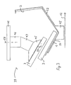
- Fig. 1 shows a schematic representation of a device with container carriers 1 according to the invention.
- the container carrier 1 are mounted on treadmills 11, extending in the direction of the arrow 12 move.
- treadmills 11 and container carriers 1 For the expert, a number of known Configurations of treadmills 11 and container carriers 1 can be seen, all of which are equally usable.
- the container carriers 1 may be prismatic hollow boxes, in where the container 2 can be used.
- the prism holders 1 have over two transverse to the direction of movement 12 bottom walls 21 and 22, respectively, on the sides of the prism carrier 1 with side walls 23 are completed or open. On the side wall 23 is good to see that the bottom walls 21 and 22 an angle Form 24 of approximately 90 degrees to each other.
- the containers 2 are while in the Fig. 1 with the bottom 25 in the direction of movement 12 the bottom wall 21 placed. As in the context of others Fig. Can still be seen, the container 2 also on the bottom wall 22 are placed.
- the side walls 26 of the container 2 are supported on one side of the wall 22.
- Fig. 1 three containers 2 are juxtaposed in the prism carrier 1 arranged. It can not be shown in the drawing Side stops for the container 2 may be provided with which the orientation and the fixation of the container 2 at her Position is ensured in the prism holder 1.
- a conveyor belt 13 Parallel to the treadmill 11, a conveyor belt 13 is arranged, which is in the same direction of movement, according to the Arrow 14, as the treadmill 11 moves. But it is also possible to operate the device in countercurrent operation.
- food slices come every kind of oblong, round, angular, oval or geometrically more complicated, such as by polygons approximated elements in question, wherein advantageously two dimensions the food slices vary widely such as width and height.
- the food slices 3 are of a first optical Detection station 31 with a detection cone 32 on the conveyor belt 13 recorded in their position and orientation and to a Control device 33 further reported.
- the control device 33 controls a first picker device 34, the predetermined one Food discs 3 picks off the conveyor belt 13 and in a container 2 stores.
- some containers are 2 completely filled, which in the illustrated embodiment three food slices 3 means some containers are 2 only partially filled, even if they already have the filling area have left the first picker 34.
- a second optical detection station 35 with a Detection cone 32 and a second picker device 36 are provided, which in turn are controlled by the control device 33.
- more than two picker devices 34, 36 are provided that only one detection station 31 is used and that, for example, wider or a plurality of conveyor belts 13, e.g. on both sides of the treadmill 11th are arranged.
- a gripper 40 is provided, which described in more detail in connection with FIG. 8 becomes.
- the picker device 34 or shown in FIG 36 corresponds to the teaching of EP 0 250 470, but it can also be replaced by any other picker device, with the food slices lifted off a first conveyor and can be moved to a second conveyor.
- FIG. 2 shows a schematic illustration of a gripper 40 for use with a container carrier 1 according to the invention in Cross section, wherein the gripper 40 in a first orientation for flat storage of a food slice 3 in the container 2 is aligned.
- the container carrier shown in FIG 1 is more complex than that according to FIG. 1. Same Features are provided in all figures with the same reference numerals.
- the container carrier 1 is on at least one connection support 15 attached, which are attached to the treadmill 11, which moves in the direction of arrow 12.
- the container carrier 1 is a cross-sectional view of four polygons 51, 52, 53 and 54 composed. The polygons 52 and 51 and 53, respectively form the boundaries for the bottom 25 and the side walls 26th of the container 2.
- the container 2 comprises a body of revolution, e.g. a truncated conical deformable paper container.
- the short side edge 54 forms a stop for the upper side wall 26.
- the gripper 40 is attached to a base plate 41 of the picker device 34 attached.
- the gripper 40 has two together set arms 42 and 43. Between the arms 42 and 43 is a Provided joint, with the angle 44 can be changed, for example between 90 and 270 degrees.
- Fig. 2 is the Gripper 40 in a position 38 with an angle 44 of approximately 150 degrees, with the gripper 40 at an angle of 135 degrees to the sucked under the suction device 45 Food slice 3 flat on the bottom 25 of the container 2 to sell.
- the front end of the gripper 40 thus has an angle 59 of, for example, 45 degrees with the horizontal.
- a suction device 45 may also be any other recording device be provided for food slices 3, since it on the pivotability of the same about a perpendicular to Transport direction 12 and transverse to the conveyor belts 11 extending Axle arrives. It is also possible that the Picker 34 moves the gripper 40 about other axes, to the food slices 3 of the conveyor belt thirteenth in the direction of the conveyor belts 11 and the container 3 to move.
- floor 52 and the side wall 51 are also features to understand that consist of a grid construction and / or which includes only individual noses or struts with which the containers 2 are held so that the bottom or the Side walls of the container 2 parallel to the bottom or the side wall of the container carrier 1 shown in FIGS.
- FIG. 3 shows a schematic representation of the gripper 40, in a second orientation 39 for standing storage a Food slice 3 is aligned in the container 2.
- Axis 46 may be every single food slice 3 be aligned according to FIG. 2 or according to FIG. 3, to be placed lying or standing in the container 2.
- the gripper 40 can also rigidly connected arms 42 and 43 and for the illustrated in Fig. 3 vertical Rotate axis 58.
- FIGS. 4 to 7 various pack configurations in containers 3 to create, where the upper drawings each have a cross section and the lower drawings show a plan view.
- 4 shows five flat food discs 3, Fig. 5 five standing juxtaposed food slices 3, Fig. 6 five standing next to each other Food slices 3, on which another food slice 3 is lying down.
- the food slices 3 at inclined walls 26 also slightly inclined.
- FIGS Configurations include a lowest lying flat Food slice, on the standing food slices arranged, covered by a flat food slice are.
- the device with gripper 40 can also be used in any other type of container, for example, cuboid or with ovaloid soil.
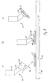
- Fig. 8 shows a schematic representation of a suction device 40 when picking up a food slice 3.
- the Suction device 40 has under the arms 41 and 42 via a Bellows 45, which in Fig. 8 a) corresponding to the arrow 47 in Direction of the conveyor belt 13 is lowered.
- Fig. 8 b) shows the suction device 40 when placing the bellows 45 on the food slice 3.
- the area 48 is compressed, while the opposite region 49 is stretched is. Following this, the suction device 40 becomes corresponding Fig.
Landscapes
- Engineering & Computer Science (AREA)
- Mechanical Engineering (AREA)
- Robotics (AREA)
- Life Sciences & Earth Sciences (AREA)
- Food Science & Technology (AREA)
- Specific Conveyance Elements (AREA)
- Supplying Of Containers To The Packaging Station (AREA)
- Container Filling Or Packaging Operations (AREA)
- Attitude Control For Articles On Conveyors (AREA)
- Intermediate Stations On Conveyors (AREA)
- Electrotherapy Devices (AREA)
Description
- Fig. 1
- eine schematische Darstellung einer Vorrichtung mit Behälterträgern gemäss der Erfindung,
- Fig. 2
- eine schematische Darstellung eines Greifers zum Einsatz mit einem Behälterträger gemäss der Erfindung in einer ersten Ausrichtung zur flachen Ablage einer Nahrungsmittelscheibe,
- Fig. 3
- eine schematische Darstellung des Greifers nach Fig. 2 in einer zweiten Ausrichtung zur stehenden Ablage einer Nahrungsmittelscheibe,
- Fig. 4 bis 7
- schematische Darstellungen von verschiedenen Packkonfigurationen in Behältern, und
- Fig. 8
- eine schematische Darstellung einer Saugvorrichtung beim Aufgreifen einer Nahrungsmittelscheibe.
Claims (10)
- Vorrichtung zur Gruppenbildung zum Einsetzen von einzelnen Stückgütern (3) in einen Behälter (2)mit einem Zufuhrförderer (13) zur Zufuhr einzelner Stückgüter (3), die in geordneter oder ungeordneter Formation auf dem Zufuhrförderer (13) fortbewegt werden,mit mindestens einer Pickervorrichtung (34), die über eine Greifvorrichtung (40) verfügt, mit der Stückgüter (3) einzeln oder in Gruppen von dem Zufuhrförderer (13) abholbar sind,mit einer Fördervorrichtung für die Pickervorrichtung mit mindestens einem Behälterträger (1) ,mit einer Ladevorrichtung undmit einer Steuervorrichtung (33), mit der der Zufuhrförderer (13) und/oder die Fördervorrichtung, und/oder die Ladevorrichtung steuerbar ist, dadurch gekennzeichnet, dass der Behälterträger einen Boden (21) und eine Seitenwand (22) aufweist, welche unter jeweils einem Winkel (28 bzw. 29) gegenüber der Horizontalen der Fördervorrichtung geneigt sind, so dass die Behälter (2) mit ihrem Boden (25) auf dem Boden (52) des Behälterträgers (1) oder mit ihrem Boden (25) auf der besagten Seitenwand (51) des Behälterträgers (1) absetzbar sind, dass in der Ladevorrichtung Behälter (2) wahlweise mit ihrem Boden (25) auf dem Boden (52) des Behälterträgers (1) oder mit ihrem Boden (25) auf der besagten Seitenwand (51) des Behälterträgers (1) absetzbar sind, und dass beim Eingang in die Pickervorrichtung (34) zumindest teilweise leere Behälter (2) durch Ausrichtung der Greifvorrichtung (40) in einer ersten (38) oder zweiten (39) Position wahlweise mit stehenden oder liegenden Stückgütern (3) füllbar sind.
- Vorrichtung nach Anspruch 1, dadurch gekennzeichnet, dass das vordere Ende (46) der Greifvorrichtung (40) einen Winkel (59) zwischen 30 und 60 Grad gegenüber der horizontalen Ebene oder der Ebene des Bodens (25) von zu befüllenden Behältern (2) aufweist.
- Vorrichtung nach Anspruch 2, dadurch gekennzeichnet, dass sie eine Sauggreifvorrichtung aufweist, deren Saugfläche während des Aufpickvorganges (48, 49) deformierbar ist, oder dass die Sauggreifvorrichtung ein mechanisch gesteuerter Sauggreifer ist, dessen Frontfläche gegenüber der Horizontalen verschwenkbar ist.
- Vorrichtung nach einem der vorstehenden Ansprüche, dadurch gekennzeichnet, dass die Greifvorrichtung (40) über zwei aneinander angelenkte Arme (42, 43) verfügt, mit denen das vordere Ende (45) der Greifvorrichtung mindestens zwischen einer ersten Position (38) und einer zweiten Position (39) verschwenkbar (46) ist.
- Vorrichtung nach einem der vorstehenden Ansprüche, dadurch gekennzeichnet, dass die erste (38) und die zweite (39) Position einen Winkel (59) von ungefähr 45 Grad mit der Horizontalen bilden, so dass das vordere Ende (45) der Greifvorrichtung (40) zwischen den beiden besagten Positionen (38, 39) um 90 Grad verschwenkbar ist.
- Vorrichtung nach einem der vorstehenden Ansprüche 1 bis 3, dadurch gekennzeichnet, dass die Greifvorrichtung (40) über einen zur Vertikalen geneigten, um eine vertikale Achse (58) drehbaren Arm (42, 43) verfügt, wobei durch eine Drehung des Armes (42, 43) um 180 Grad um die besagte Achse (58) das vordere Ende (45) der Greifvorrichtung mindestens zwischen einer ersten Position (38) und einer zweiten Position (39) verschwenkbar ist.
- Vorrichtung nach einem der vorstehenden Ansprüche, dadurch gekennzeichnet, dass die Behälterträger (1) quer zur Förderrichtung (12) auf der Fördervorrichtung (11) befestigt sind und/oder dass eine Vielzahl von Behälterträgern (1) in einem konstanten Abstand zueinander angeordnet sind.
- Vorrichtung nach einem der vorstehenden Ansprüche, dadurch gekennzeichnet, dass vor dem Zufuhrförderer (13) mindestens eine Bildaufnahmeeinheit (31) angeordnet ist, mit der die Stückgüter (3) auf dem Zufuhrförderer (13) in ihrer jeweiligen Position erfassbar sind, wobei die von der Bildaufnahmeeinheit (31) ermittelten Datensignale an die Steuereinrichtung (33) übermittelbar sind und die gepickten Stückgüter (3) in vorbestimmter Orientierung in einen vorbestimmten Behälter (2) platzierbar sind.
- Verfahren zum Einsetzen von einzelnen Stückgütern (3) in einen Behälter (2) mit den Verfahrensschritten des Aufpickens von Stückgütern (3) mit Hilfe einer Greifvorrichtung (40) und des Ablegens der gepickten Stückgüter (3) in die in einer Fördervorrichtung angeordneten Behälter (2), dadurch gekennzeichnet, dass die Behälter (2) wahlweise mit ihrem Boden (25) auf einen Boden (52) eines Behälterträgers. (1) oder mit ihrem Boden (25) auf einer Seitenwand (51) des Behälterträgers (1) abgesetzt werden, wobei ein Boden (21) und eine Seitenwand (22) des Behälterträgers (1) unter jeweils einem Winkel (28 bzw. 2g) gegenüber der Horizontalen der Förder vorrichtung geneigt sind , und dass durch Anordnung der Greifvorrichtung (40) in einer ersten (38) oder in einer zweiten (39) Position die Stückgüter (3) wahlweise liegend oder stehend in den besagten Behältern (2) abgelegt werden.
- Verfahren nach Anspruch 9, dadurch gekennzeichnet, dass zuerst eine erste Anzahl von 4 bis 7 stehenden Stückgütern (3) und danach auf den Kanten der stehenden Stückgüter (3) eine zweite Anzahl von 0 bis 3 liegenden Stückgütern (3) in dem Behälter (2) abgelegt werden.
Applications Claiming Priority (2)
| Application Number | Priority Date | Filing Date | Title |
|---|---|---|---|
| CH10972000 | 2000-05-31 | ||
| CH10972000 | 2000-05-31 |
Publications (2)
| Publication Number | Publication Date |
|---|---|
| EP1160166A1 EP1160166A1 (de) | 2001-12-05 |
| EP1160166B1 true EP1160166B1 (de) | 2003-06-04 |
Family
ID=4557299
Family Applications (1)
| Application Number | Title | Priority Date | Filing Date |
|---|---|---|---|
| EP01810507A Expired - Lifetime EP1160166B1 (de) | 2000-05-31 | 2001-05-22 | Vorrichtung zur Gruppenbildung sowie Verfahren zum Betreiben derselben |
Country Status (7)
| Country | Link |
|---|---|
| US (1) | US6701694B2 (de) |
| EP (1) | EP1160166B1 (de) |
| JP (1) | JP2002080016A (de) |
| AT (1) | ATE242154T1 (de) |
| CA (1) | CA2347572C (de) |
| DE (1) | DE50100279D1 (de) |
| ES (1) | ES2199924T3 (de) |
Cited By (2)
| Publication number | Priority date | Publication date | Assignee | Title |
|---|---|---|---|---|
| EP2236424A1 (de) | 2009-03-30 | 2010-10-06 | Veltru AG | Verfahren und Vorrichtung zum Einlegen von Einzelprodukten in Behälter in einer Roboterstrasse |
| WO2012163666A1 (de) | 2011-05-30 | 2012-12-06 | Knapp Ag | Kommissioniersystem mit einem knickarmgreifer |
Families Citing this family (27)
| Publication number | Priority date | Publication date | Assignee | Title |
|---|---|---|---|---|
| US6799411B2 (en) | 2002-02-13 | 2004-10-05 | Sig Pack Systems, Ag | Apparatus and process for inserting individual piece goods into containers |
| DE50304180D1 (de) * | 2002-04-02 | 2006-08-24 | Bosch Gmbh Robert | Verfahren und Vorrichtung zum Einfüllen von Stückgütern in Behälter |
| NZ518851A (en) * | 2002-05-08 | 2004-12-24 | Anzpac Systems Ltd | Sorting apparatus and method |
| US20050220580A1 (en) * | 2004-03-15 | 2005-10-06 | Thomas Arnold | Dual mode stacking system and method of use |
| WO2008003350A1 (de) * | 2006-07-04 | 2008-01-10 | Robert Bosch Gmbh | Verfahren zum befüllen von behältern mit stückgütern |
| DE102007028680A1 (de) * | 2007-06-21 | 2008-12-24 | Elau Elektronik-Automations-Ag | Gruppierungsstation |
| US8931240B2 (en) | 2008-10-27 | 2015-01-13 | Formax, Inc. | Shuttle system and method for moving food products into packaging |
| FR2939769B1 (fr) * | 2008-12-11 | 2010-12-31 | Ballina Freres De | Procede et installation de distribution de produits pour leur conditionnement |
| IT1397039B1 (it) * | 2009-12-30 | 2012-12-28 | Ds4 S R L | Macchina per impacchettare una pluralita' di oggetti piatti e relativo metodo. |
| US8781616B2 (en) * | 2011-06-27 | 2014-07-15 | The Procter & Gamble Company | Robotic unscrambler and method |
| JP5863553B2 (ja) * | 2012-05-01 | 2016-02-16 | 住友重機械工業株式会社 | 仕分けシステム |
| US8997438B1 (en) | 2012-09-18 | 2015-04-07 | David M. Fallas | Case packing system having robotic pick and place mechanism and dual dump bins |
| ITMI20150573A1 (it) * | 2015-04-21 | 2016-10-21 | Ima Spa | Dispositivo e metodo di trasferimento contenitori |
| US10766645B2 (en) * | 2015-08-14 | 2020-09-08 | Intercontinental Great Britain LLC | Food conveyor and packaging systems and methods |
| US11550303B2 (en) | 2017-01-02 | 2023-01-10 | Robotek Otomasyon Teknolojileri Sanayi Ticaret Limited Sirketi | Robotic production line and methods of flexible and chaotic production |
| CN107775474A (zh) * | 2017-11-06 | 2018-03-09 | 重庆椿本智能科技有限公司 | 一种打磨机构 |
| CN108891652A (zh) * | 2018-04-18 | 2018-11-27 | 江门新乐贝食品有限公司 | 盒装字母饼干的装料生产线以及字母饼干的装盒方法 |
| US10980187B2 (en) | 2019-02-21 | 2021-04-20 | Omachron Intellectual Property Inc. | Lighting system for indoor cultivation facility |
| JP6978085B2 (ja) * | 2019-03-22 | 2021-12-08 | 株式会社フジキカイ | 物品供給装置 |
| DE102019112867A1 (de) * | 2019-05-16 | 2020-11-19 | Homag Automation Gmbh | Robotergreifer, Industrieroboter, Handhabungssystem und Verfahren zur Entnahme plattenförmiger Werkstücke von einem Stapel |
| CN111252466A (zh) * | 2020-01-23 | 2020-06-09 | 广东伟创五洋智能设备有限公司 | 分拣皮带机 |
| CN112918717B (zh) * | 2021-03-25 | 2024-08-09 | 苏州富强科技有限公司 | 交替式笔记本装盒装置 |
| CN112959063A (zh) * | 2021-04-19 | 2021-06-15 | 苏州博古特智造有限公司 | 一种手机组装生产线治具及工件辅助搬运装置 |
| CN114194486B (zh) * | 2021-11-09 | 2024-05-03 | 无锡先导智能装备股份有限公司 | 定位压紧装置及电芯打包设备 |
| US12303382B2 (en) * | 2022-09-13 | 2025-05-20 | Johnson & Johnson Surgical Vision, Inc. | Intraocular lens load assembly system |
| CN116374261A (zh) * | 2023-06-05 | 2023-07-04 | 安徽光耀磁业有限公司 | 磁瓦装箱装置及磁瓦装箱方法 |
| CN117657767B (zh) * | 2023-10-23 | 2026-03-03 | 佛山市松智机器人科技有限公司 | 一种面饼叠层装盘机 |
Family Cites Families (21)
| Publication number | Priority date | Publication date | Assignee | Title |
|---|---|---|---|---|
| US1243406A (en) * | 1917-03-06 | 1917-10-16 | Steel Utilities Inc | Crating apparatus for bottles and the like. |
| FR1442386A (fr) * | 1965-04-27 | 1966-06-17 | Heliot Maurice Ets | Dispositif de groupage de sachets dans un container |
| US3691717A (en) * | 1970-12-01 | 1972-09-19 | Swift & Co | Method and apparatus for filling cartons |
| US4203274A (en) * | 1977-12-08 | 1980-05-20 | Pennwalt Corporation | Apparatus for packing articles of fruit into boxes |
| US4189898A (en) * | 1978-06-29 | 1980-02-26 | Diamond International Corporation | Egg packer |
| DK151302C (da) * | 1981-03-16 | 1988-06-27 | Stormax Aps | Fremgangsmaade til gruppering, orientering og emballering af genstande samt et anlaeg til udoevelse af fremgangsmaaden |
| US4428175A (en) * | 1982-06-16 | 1984-01-31 | G. W. Haab Co., Inc. | Energy free loader |
| CH672089A5 (de) | 1985-12-16 | 1989-10-31 | Sogeva Sa | |
| DE3662248D1 (en) * | 1986-02-01 | 1989-04-13 | Frisco Findus Ag | Packing machine |
| DE3801279C1 (de) * | 1988-01-19 | 1989-05-24 | Hartmut 4044 Kaarst De Klapp | |
| US5025612A (en) * | 1989-11-29 | 1991-06-25 | Roberts Systems, Inc. | Inverted tray container loading apparatus |
| DE59100645D1 (de) | 1990-04-23 | 1994-01-13 | Sig Schweiz Industrieges | Verfahren und Vorrichtung zur Bildung von Gruppen von Nahrungsmittelscheiben. |
| CH681590A5 (de) | 1991-07-29 | 1993-04-30 | Sig Schweiz Industrieges | |
| US5256029A (en) | 1991-04-22 | 1993-10-26 | Sig Schweizerische Industrie-Gesellschaft | Method and apparatus for forming article groups |
| US5251422A (en) * | 1992-03-26 | 1993-10-12 | Prototype Equipment Corporation | Potato chip package vertical packaging machine |
| DE4339002C2 (de) * | 1993-11-11 | 1997-07-10 | Kommissionier Und Handhabungst | Einrichtung für die Kommissionierung von Stückgut aus Warenbahnen |
| DE9410970U1 (de) * | 1994-07-12 | 1994-10-27 | Ostma Maschinenbau GmbH, 53909 Zülpich | Anlage zum Einstapeln von mit nicht lagefixiertem Gut gefüllten Verpackungsbeuteln in einen Verpackungsbehälter |
| US5655355A (en) * | 1995-08-07 | 1997-08-12 | Dimension Industries, Inc. | Packaging system for stacking articles in cartons |
| US5855105A (en) * | 1997-06-30 | 1999-01-05 | Cloud Corporation | Cartoner with direct dropping of pouches into cartons |
| DE19930368A1 (de) * | 1999-07-01 | 2001-03-29 | Loesch Verpackungstechnik Gmbh | Verfahren und Vorrichtung zum Verpacken von flachen Produkten |
| US6370844B1 (en) * | 2000-01-31 | 2002-04-16 | Eveready Battery Company, Inc. | Product packaging arrangement using invisible marking for product orientation |
-
2001
- 2001-05-15 CA CA002347572A patent/CA2347572C/en not_active Expired - Lifetime
- 2001-05-22 ES ES01810507T patent/ES2199924T3/es not_active Expired - Lifetime
- 2001-05-22 AT AT01810507T patent/ATE242154T1/de not_active IP Right Cessation
- 2001-05-22 DE DE50100279T patent/DE50100279D1/de not_active Expired - Lifetime
- 2001-05-22 EP EP01810507A patent/EP1160166B1/de not_active Expired - Lifetime
- 2001-05-30 US US09/866,583 patent/US6701694B2/en not_active Expired - Lifetime
- 2001-05-31 JP JP2001165808A patent/JP2002080016A/ja active Pending
Cited By (2)
| Publication number | Priority date | Publication date | Assignee | Title |
|---|---|---|---|---|
| EP2236424A1 (de) | 2009-03-30 | 2010-10-06 | Veltru AG | Verfahren und Vorrichtung zum Einlegen von Einzelprodukten in Behälter in einer Roboterstrasse |
| WO2012163666A1 (de) | 2011-05-30 | 2012-12-06 | Knapp Ag | Kommissioniersystem mit einem knickarmgreifer |
Also Published As
| Publication number | Publication date |
|---|---|
| EP1160166A1 (de) | 2001-12-05 |
| CA2347572A1 (en) | 2001-11-30 |
| DE50100279D1 (de) | 2003-07-10 |
| ATE242154T1 (de) | 2003-06-15 |
| US6701694B2 (en) | 2004-03-09 |
| CA2347572C (en) | 2009-10-20 |
| JP2002080016A (ja) | 2002-03-19 |
| US20010049923A1 (en) | 2001-12-13 |
| ES2199924T3 (es) | 2004-03-01 |
Similar Documents
| Publication | Publication Date | Title |
|---|---|---|
| EP1160166B1 (de) | Vorrichtung zur Gruppenbildung sowie Verfahren zum Betreiben derselben | |
| DE3786083T2 (de) | Verfahren und vorrichtung zur selbsttätigen verladung von plätzchen, mit doppelter entladung. | |
| DE69201268T2 (de) | Apparat zum Überführen von Gegenständen wie Eier unter Verwendung einer Bürste. | |
| DE68923611T2 (de) | Verfahren und apparat zur beförderung von gegenständen. | |
| DE68922359T2 (de) | Verfahren und Vorrichtung zum Ordnen von Gegenständen. | |
| EP2353149B1 (de) | Verfahren und transporteinrichtung zur rücknahme von leergut, insbesondere von flaschen und dosen | |
| CH663185A5 (de) | Vorrichtung zum selbsttaetigen einfuellen von gestapelten, scheibenfoermigen gegenstaenden in einseitig offene verpackungsbehaelter. | |
| EP3246272B1 (de) | Rutsche und sortiereinrichtung sowie verfahren zum sortieren von stückgut | |
| EP4126719B1 (de) | Verfahren zum sortieren von artikeln und sortiervorrichtung | |
| DE102016105570B4 (de) | Umsetz-Vorrichtung für Produkte sowie Verfahren zu ihrem Betrieb | |
| CH428548A (de) | Eier-Transport- und Verpackungs- Vorrichtung | |
| EP2936986B1 (de) | Schaschlikmaschine und verfahren zum herstellen von schaschlikspiessen | |
| DE4336885A1 (de) | Kommissionierungsanlage für Apothekenprodukte | |
| EP1008521A2 (de) | Vorrichtung zum Zuführen von Gruppen flachseitig aneinanderliegender, Scheibenförmiger Produkte, insbesondere Biskuits, in Verpackungsbehälter | |
| EP2635509A2 (de) | Vorrichtung und verfahren zum schnellen zusammenstellen von kommissionsware für den transport | |
| DE3608079A1 (de) | Robotersystem zum verpacken konischer gegenstaende | |
| DE2415376A1 (de) | Vorrichtung zum verpacken von eiern in behaelter | |
| DE4024451A1 (de) | Geraet zum beschicken von verpackungsmaschinen mit stapeln aus geschichtetem material | |
| DE2701028C2 (de) | Vorrichtung zum Palettieren von gebündelten Blattstapeln | |
| EP0340164B1 (de) | Vorrichtung zum Umverteilen von Lebensmittelscheiben von einem ersten auf ein zweites Transportorgan | |
| EP0771748B1 (de) | Vorrichtung zum ausgerichteten Zuführen und Auflockern von Stapeln flacher Gegenstände | |
| DE3910230C1 (en) | Apparatus for collecting, transporting and discharging mushrooms | |
| EP0416627B1 (de) | Verfahren und Vorrichtung zum Lagern in und zum automatischen Entnehmen von Stückgutsorten aus Regalen in Grosslagern | |
| EP2045024B1 (de) | Sortiervorrichtung für Pflanzen | |
| EP1210270B1 (de) | Tray zur aufnahme und zum transport von flaschen |
Legal Events
| Date | Code | Title | Description |
|---|---|---|---|
| PUAI | Public reference made under article 153(3) epc to a published international application that has entered the european phase |
Free format text: ORIGINAL CODE: 0009012 |
|
| AK | Designated contracting states |
Kind code of ref document: A1 Designated state(s): AT BE CH CY DE DK ES FI FR GB GR IE IT LI LU MC NL PT SE TR |
|
| AX | Request for extension of the european patent |
Free format text: AL;LT;LV;MK;RO;SI |
|
| 17P | Request for examination filed |
Effective date: 20020109 |
|
| 17Q | First examination report despatched |
Effective date: 20020503 |
|
| AKX | Designation fees paid |
Free format text: AT BE CH CY DE DK ES FI FR GB GR IE IT LI LU MC NL PT SE TR |
|
| GRAH | Despatch of communication of intention to grant a patent |
Free format text: ORIGINAL CODE: EPIDOS IGRA |
|
| GRAH | Despatch of communication of intention to grant a patent |
Free format text: ORIGINAL CODE: EPIDOS IGRA |
|
| GRAA | (expected) grant |
Free format text: ORIGINAL CODE: 0009210 |
|
| AK | Designated contracting states |
Designated state(s): AT BE CH CY DE DK ES FI FR GB GR IE IT LI LU MC NL PT SE TR |
|
| PG25 | Lapsed in a contracting state [announced via postgrant information from national office to epo] |
Ref country code: IE Free format text: LAPSE BECAUSE OF FAILURE TO SUBMIT A TRANSLATION OF THE DESCRIPTION OR TO PAY THE FEE WITHIN THE PRESCRIBED TIME-LIMIT Effective date: 20030604 Ref country code: CY Free format text: LAPSE BECAUSE OF FAILURE TO SUBMIT A TRANSLATION OF THE DESCRIPTION OR TO PAY THE FEE WITHIN THE PRESCRIBED TIME-LIMIT Effective date: 20030604 Ref country code: TR Free format text: LAPSE BECAUSE OF FAILURE TO SUBMIT A TRANSLATION OF THE DESCRIPTION OR TO PAY THE FEE WITHIN THE PRESCRIBED TIME-LIMIT Effective date: 20030604 |
|
| REG | Reference to a national code |
Ref country code: GB Ref legal event code: FG4D Free format text: NOT ENGLISH |
|
| REG | Reference to a national code |
Ref country code: CH Ref legal event code: NV Representative=s name: ISLER & PEDRAZZINI AG Ref country code: CH Ref legal event code: EP |
|
| REG | Reference to a national code |
Ref country code: IE Ref legal event code: FG4D Free format text: GERMAN |
|
| REF | Corresponds to: |
Ref document number: 50100279 Country of ref document: DE Date of ref document: 20030710 Kind code of ref document: P |
|
| PG25 | Lapsed in a contracting state [announced via postgrant information from national office to epo] |
Ref country code: PT Free format text: LAPSE BECAUSE OF FAILURE TO SUBMIT A TRANSLATION OF THE DESCRIPTION OR TO PAY THE FEE WITHIN THE PRESCRIBED TIME-LIMIT Effective date: 20030904 Ref country code: GR Free format text: LAPSE BECAUSE OF FAILURE TO SUBMIT A TRANSLATION OF THE DESCRIPTION OR TO PAY THE FEE WITHIN THE PRESCRIBED TIME-LIMIT Effective date: 20030904 Ref country code: DK Free format text: LAPSE BECAUSE OF FAILURE TO SUBMIT A TRANSLATION OF THE DESCRIPTION OR TO PAY THE FEE WITHIN THE PRESCRIBED TIME-LIMIT Effective date: 20030904 |
|
| REG | Reference to a national code |
Ref country code: SE Ref legal event code: TRGR |
|
| GBT | Gb: translation of ep patent filed (gb section 77(6)(a)/1977) |
Effective date: 20031018 |
|
| REG | Reference to a national code |
Ref country code: IE Ref legal event code: FD4D |
|
| REG | Reference to a national code |
Ref country code: ES Ref legal event code: FG2A Ref document number: 2199924 Country of ref document: ES Kind code of ref document: T3 |
|
| ET | Fr: translation filed | ||
| PLBE | No opposition filed within time limit |
Free format text: ORIGINAL CODE: 0009261 |
|
| STAA | Information on the status of an ep patent application or granted ep patent |
Free format text: STATUS: NO OPPOSITION FILED WITHIN TIME LIMIT |
|
| PG25 | Lapsed in a contracting state [announced via postgrant information from national office to epo] |
Ref country code: LU Free format text: LAPSE BECAUSE OF NON-PAYMENT OF DUE FEES Effective date: 20040522 Ref country code: AT Free format text: LAPSE BECAUSE OF NON-PAYMENT OF DUE FEES Effective date: 20040522 |
|
| 26N | No opposition filed |
Effective date: 20040305 |
|
| PG25 | Lapsed in a contracting state [announced via postgrant information from national office to epo] |
Ref country code: MC Free format text: LAPSE BECAUSE OF NON-PAYMENT OF DUE FEES Effective date: 20040531 |
|
| REG | Reference to a national code |
Ref country code: CH Ref legal event code: PCAR Free format text: ISLER & PEDRAZZINI AG;POSTFACH 1772;8027 ZUERICH (CH) |
|
| PGFP | Annual fee paid to national office [announced via postgrant information from national office to epo] |
Ref country code: SE Payment date: 20091222 Year of fee payment: 10 |
|
| PGFP | Annual fee paid to national office [announced via postgrant information from national office to epo] |
Ref country code: FR Payment date: 20100608 Year of fee payment: 10 Ref country code: FI Payment date: 20100520 Year of fee payment: 10 |
|
| PGFP | Annual fee paid to national office [announced via postgrant information from national office to epo] |
Ref country code: IT Payment date: 20100527 Year of fee payment: 10 |
|
| REG | Reference to a national code |
Ref country code: SE Ref legal event code: EUG |
|
| PG25 | Lapsed in a contracting state [announced via postgrant information from national office to epo] |
Ref country code: FI Free format text: LAPSE BECAUSE OF NON-PAYMENT OF DUE FEES Effective date: 20110522 |
|
| REG | Reference to a national code |
Ref country code: FR Ref legal event code: ST Effective date: 20120131 |
|
| PG25 | Lapsed in a contracting state [announced via postgrant information from national office to epo] |
Ref country code: IT Free format text: LAPSE BECAUSE OF NON-PAYMENT OF DUE FEES Effective date: 20110522 |
|
| PG25 | Lapsed in a contracting state [announced via postgrant information from national office to epo] |
Ref country code: FR Free format text: LAPSE BECAUSE OF NON-PAYMENT OF DUE FEES Effective date: 20110531 |
|
| PG25 | Lapsed in a contracting state [announced via postgrant information from national office to epo] |
Ref country code: SE Free format text: LAPSE BECAUSE OF NON-PAYMENT OF DUE FEES Effective date: 20110523 |
|
| REG | Reference to a national code |
Ref country code: DE Ref legal event code: R082 Ref document number: 50100279 Country of ref document: DE Representative=s name: HOEGER, STELLRECHT & PARTNER PATENTANWAELTE MB, DE |
|
| REG | Reference to a national code |
Ref country code: DE Ref legal event code: R082 Ref document number: 50100279 Country of ref document: DE Representative=s name: HOEGER, STELLRECHT & PARTNER PATENTANWAELTE MB, DE Ref country code: DE Ref legal event code: R082 Ref document number: 50100279 Country of ref document: DE Representative=s name: PATENT- UND RECHTSANWALTSKANZLEI DAUB, DE |
|
| REG | Reference to a national code |
Ref country code: CH Ref legal event code: NV Representative=s name: PATENTANWALTSKANZLEI DAUB, CH |
|
| REG | Reference to a national code |
Ref country code: DE Ref legal event code: R082 Ref document number: 50100279 Country of ref document: DE Representative=s name: PATENT- UND RECHTSANWALTSKANZLEI DAUB, DE |
|
| REG | Reference to a national code |
Ref country code: DE Ref legal event code: R081 Ref document number: 50100279 Country of ref document: DE Owner name: SYNTEGON PACKAGING SYSTEMS AG, CH Free format text: FORMER OWNER: SIG PACK SYSTEMS AG, BERINGEN, CH Ref country code: DE Ref legal event code: R082 Ref document number: 50100279 Country of ref document: DE Representative=s name: PATENT- UND RECHTSANWALTSKANZLEI DAUB, DE |
|
| REG | Reference to a national code |
Ref country code: CH Ref legal event code: PFA Owner name: SYNTEGON PACKAGING SYSTEMS AG, CH Free format text: FORMER OWNER: SIG PACK SYSTEMS AG, CH |
|
| REG | Reference to a national code |
Ref country code: CH Ref legal event code: PVP |
|
| PGFP | Annual fee paid to national office [announced via postgrant information from national office to epo] |
Ref country code: ES Payment date: 20200618 Year of fee payment: 20 Ref country code: NL Payment date: 20200518 Year of fee payment: 20 Ref country code: CH Payment date: 20200522 Year of fee payment: 20 Ref country code: DE Payment date: 20200525 Year of fee payment: 20 |
|
| PGFP | Annual fee paid to national office [announced via postgrant information from national office to epo] |
Ref country code: BE Payment date: 20200518 Year of fee payment: 20 Ref country code: GB Payment date: 20200522 Year of fee payment: 20 |
|
| REG | Reference to a national code |
Ref country code: NL Ref legal event code: HC Owner name: SYNTEGON PACKAGING SYSTEMS AG; CH Free format text: DETAILS ASSIGNMENT: CHANGE OF OWNER(S), CHANGE OF OWNER(S) NAME; FORMER OWNER NAME: SIG PACK SYSTEMS AG Effective date: 20200804 |
|
| REG | Reference to a national code |
Ref country code: BE Ref legal event code: HC Owner name: SYNTEGON PACKAGING SYSTEMS AG; CH Free format text: DETAILS ASSIGNMENT: CHANGE OF OWNER(S), CHANGEMENT DE NOM DU PROPRIETAIRE; FORMER OWNER NAME: BOSCH PACKAGING SYSTEMS AG Effective date: 20200727 |
|
| REG | Reference to a national code |
Ref country code: ES Ref legal event code: PC2A Owner name: SYNTEGON PACAKAGING SYSTEMS AG Effective date: 20210115 |
|
| REG | Reference to a national code |
Ref country code: DE Ref legal event code: R071 Ref document number: 50100279 Country of ref document: DE |
|
| REG | Reference to a national code |
Ref country code: NL Ref legal event code: MK Effective date: 20210521 |
|
| REG | Reference to a national code |
Ref country code: CH Ref legal event code: PL |
|
| REG | Reference to a national code |
Ref country code: GB Ref legal event code: PE20 Expiry date: 20210521 |
|
| REG | Reference to a national code |
Ref country code: BE Ref legal event code: MK Effective date: 20210522 |
|
| REG | Reference to a national code |
Ref country code: ES Ref legal event code: FD2A Effective date: 20210827 |
|
| PG25 | Lapsed in a contracting state [announced via postgrant information from national office to epo] |
Ref country code: GB Free format text: LAPSE BECAUSE OF EXPIRATION OF PROTECTION Effective date: 20210521 |
|
| PG25 | Lapsed in a contracting state [announced via postgrant information from national office to epo] |
Ref country code: ES Free format text: LAPSE BECAUSE OF EXPIRATION OF PROTECTION Effective date: 20210523 |