EP1160314A1 - Procédé pour l'ébullition du moût et chaudière à moût - Google Patents
Procédé pour l'ébullition du moût et chaudière à moût Download PDFInfo
- Publication number
- EP1160314A1 EP1160314A1 EP01111607A EP01111607A EP1160314A1 EP 1160314 A1 EP1160314 A1 EP 1160314A1 EP 01111607 A EP01111607 A EP 01111607A EP 01111607 A EP01111607 A EP 01111607A EP 1160314 A1 EP1160314 A1 EP 1160314A1
- Authority
- EP
- European Patent Office
- Prior art keywords
- wort
- gap
- profiles
- vertical
- layers
- Prior art date
- Legal status (The legal status is an assumption and is not a legal conclusion. Google has not performed a legal analysis and makes no representation as to the accuracy of the status listed.)
- Withdrawn
Links
- 238000000034 method Methods 0.000 title claims description 9
- 238000009835 boiling Methods 0.000 title claims description 8
- RYGMFSIKBFXOCR-UHFFFAOYSA-N Copper Chemical compound [Cu] RYGMFSIKBFXOCR-UHFFFAOYSA-N 0.000 title 1
- 229910052802 copper Inorganic materials 0.000 title 1
- 239000010949 copper Substances 0.000 title 1
- 235000011194 food seasoning agent Nutrition 0.000 claims description 2
- 238000001704 evaporation Methods 0.000 abstract description 8
- 230000008020 evaporation Effects 0.000 abstract description 8
- 239000002245 particle Substances 0.000 abstract description 3
- 239000000126 substance Substances 0.000 abstract description 2
- 235000013599 spices Nutrition 0.000 description 4
- QMMFVYPAHWMCMS-UHFFFAOYSA-N Dimethyl sulfide Chemical compound CSC QMMFVYPAHWMCMS-UHFFFAOYSA-N 0.000 description 3
- 238000011161 development Methods 0.000 description 3
- 230000018109 developmental process Effects 0.000 description 3
- 230000015572 biosynthetic process Effects 0.000 description 2
- 238000000605 extraction Methods 0.000 description 1
- 238000004519 manufacturing process Methods 0.000 description 1
- 230000000149 penetrating effect Effects 0.000 description 1
- 230000002040 relaxant effect Effects 0.000 description 1
- 230000028327 secretion Effects 0.000 description 1
Images

Classifications
-
- C—CHEMISTRY; METALLURGY
- C12—BIOCHEMISTRY; BEER; SPIRITS; WINE; VINEGAR; MICROBIOLOGY; ENZYMOLOGY; MUTATION OR GENETIC ENGINEERING
- C12C—BEER; PREPARATION OF BEER BY FERMENTATION; PREPARATION OF MALT FOR MAKING BEER; PREPARATION OF HOPS FOR MAKING BEER
- C12C13/00—Brewing devices, not covered by a single group of C12C1/00 - C12C12/04
- C12C13/02—Brew kettles
-
- C—CHEMISTRY; METALLURGY
- C12—BIOCHEMISTRY; BEER; SPIRITS; WINE; VINEGAR; MICROBIOLOGY; ENZYMOLOGY; MUTATION OR GENETIC ENGINEERING
- C12C—BEER; PREPARATION OF BEER BY FERMENTATION; PREPARATION OF MALT FOR MAKING BEER; PREPARATION OF HOPS FOR MAKING BEER
- C12C7/00—Preparation of wort
- C12C7/28—After-treatment, e.g. sterilisation
-
- C—CHEMISTRY; METALLURGY
- C12—BIOCHEMISTRY; BEER; SPIRITS; WINE; VINEGAR; MICROBIOLOGY; ENZYMOLOGY; MUTATION OR GENETIC ENGINEERING
- C12C—BEER; PREPARATION OF BEER BY FERMENTATION; PREPARATION OF MALT FOR MAKING BEER; PREPARATION OF HOPS FOR MAKING BEER
- C12C9/00—Methods specially adapted for the making of beerwort
- C12C9/02—Beerwort treatment; Boiling with hops; Hop extraction
Definitions
- the invention relates to a method for boiling wort, where the wort is heated externally, then in a wort pan is introduced and relaxed and in a vapor room distributed above a maximum wort level and on the Spice mirror is piled up. Furthermore, the Invention a wort kettle for external wort boiling with a Vapor space and a wort inlet device, so is designed and arranged to heat externally, distributed into the vapor space above a maximum wort level and layered on top of the wort level.
- wort is used in external wort boiling pumped from a wort pan into an external heat exchanger, heated there to a temperature of approx. 103 to 108 ° C and conveyed back into the wort kettle.
- a central wort inlet device is used for distribution the spice in the vapor space, being a relaxation takes place.
- the vaporized vapors are along with undesirable flavoring substances are usually central arranged vapor deduction deducted.
- the wort inlet device has the type mentioned at the beginning a central riser, whose above the maximum wort level arranged mouth opening deflector cone with an axial spacing is put up.
- the relaxing spice is through the Deflection cone deflected downward like an umbrella and along a concentric ring layered on the wort mirror.
- DE-PS 3 018 811 are also wort infeed devices with several concentric and / or radial over the Pan cross-section distributed distributor openings known.
- the invention has for its object the evaporation surface with undisturbed withdrawal of the brothers and thus one efficient evaporation of the unwanted flavoring essential to enlarge or improve.
- the wort kettle of the type mentioned is in accordance with the invention characterized in that the wort inlet device is centrally located in the vapor room and several in mutually angular distance arranged gap limiting profiles has, the columns are formed so that the through the column between the boundary profiles Season in radially outward, essentially vertical Layers fanned out and layered on top of the wort level becomes.
- the invention is enlarged by vertical formation of the formed wort layers the number of layers and thus the generally available evaporation areas. More essential but the fact is that on both sides of the wort layers escaping vapors with the unwanted flavorings (e.g. dimethyl sulfide DMS) undisturbed and without Penetrating a layer of wort upwards. For this, the brothers stand between the free spaces the neighboring vertical layers. It turns out is also of considerable advantage that the vertical radial Spread out the layers evenly and guaranteed star-shaped impact of the wort on the wort level, which approximates the state of a piston flow the seasoning in the pan down and thus one uniform circulation of all wort particles results.
- the unwanted flavorings e.g. dimethyl sulfide DMS
- the radially outward vertical layers in distributed uniform angular distances.
- the layer thickness and the number of screws can be easily adjusted or structural variation of the switching limitation profiles to change.
- the gap limitation profiles are preferably concentric arranged around a vertical central axis of the wort kettle. Are also in accordance with the preferred embodiment the column between the boundary profiles above and below limited in a common horizontal plane.
- Each profile can have a circle, part circle, triangle or have a trapezoidal cross-section, the profiling is preferably designed so that the crevices to generate an approximately laminar flow continuously are shaped.
- each profile is radially running at the top and bottom Slotted hole of a horizontal support plate, the gap widths by radial adjustment of the profiles changeable within the scope of the game available in the slot are.
- the profiles are used to simplify their manufacture preferably arranged concentrically and parallel to the pan axis, so that vertical layers of wort are evenly distributed Result in angular distribution. But it can lead to another Expansion of the evaporation surfaces may be expedient, the column by an angle ⁇ with respect to the vertical wort pan central axis to be arranged inclined.
- An angle ⁇ ⁇ 20 ° has proven to be suitable; under certain circumstances, however even stronger inclinations up to 45 ° are sensible and practical his.
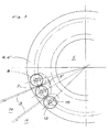
- the new wort kettle is in one schematic axial section or a horizontal section shown.
- the wort kettle 1 has a central inlet connection 11, which has a wort inlet at its upper end 2 carries.
- the wort inlet head 2 is, as shown in FIG. 1, arranged above the (maximum) wort level 5.
- the Wort inlet head is at the top and bottom by horizontal plates 6 or 6 'limited.
- the horizontal plates 6, 6 ' are over 24 pipe profiles 8, threaded pin 13 and in the drawing outer nuts, not shown, together to form a cage Unit connected. Between every two neighboring ones Pipe profiles 8 are formed by vertical columns the boiling wort from the interior 9 of the wort inlet head 8 can escape radially outwards into the vapor space 4.
- the screw bolts 13 arranged at the top and bottom of the cylindrical gap-limiting profiles 8 are guided in radial elongated holes 10.
- the gap limitation profiles can be adjusted radially in order to be able to adjust the width of the gap 7 formed between them. With the same profiles, these gaps 7 can be made narrower by moving the screw bolts 13 inwards and by moving the screw bolts 13 outwards.
- All gap-limiting profiles 8 are preferably of identical design and are arranged on a concentric circle around the central axis in order to standardize the radially outwardly directed and vertical layers 3 and to layer the wort uniformly and in a star shape on the wort level.
- the end face of the wort inlet head 2 is a Deflection cone 12 arranged, the incoming and axial upward wort flow evenly in radial directions redirects and enters the 24 column.
- the partial wort flows are evenly above the Vapor room 4 distributed and in a total of 24 vertical layers divided up.
- the vertical layers can be through intermediate plates parallel to the horizontal plates 6, 6 'or by means of suitable Ring plates divided into one or more altitudes be, which also increases the stability of the cage-shaped Inlet head is enlarged.
- Pipe or cylinder profiles 8 can also have other profile cross sections and profiles that delimit the columns be used. Due to the inclination of the gap limitation profiles 8 opposite the central axis, the layers can face the vertical direction are more or less inclined, whereby the vapors are still inclined by the remaining Sectors can subtract freely upwards.
Landscapes
- Chemical & Material Sciences (AREA)
- Organic Chemistry (AREA)
- Engineering & Computer Science (AREA)
- Bioinformatics & Cheminformatics (AREA)
- Life Sciences & Earth Sciences (AREA)
- Biochemistry (AREA)
- Health & Medical Sciences (AREA)
- General Engineering & Computer Science (AREA)
- General Health & Medical Sciences (AREA)
- Genetics & Genomics (AREA)
- Food Science & Technology (AREA)
- Wood Science & Technology (AREA)
- Zoology (AREA)
- Distillation Of Fermentation Liquor, Processing Of Alcohols, Vinegar And Beer (AREA)
Applications Claiming Priority (2)
| Application Number | Priority Date | Filing Date | Title |
|---|---|---|---|
| DE10026573 | 2000-05-30 | ||
| DE2000126573 DE10026573C1 (de) | 2000-05-30 | 2000-05-30 | Verfahren zum Würzekochen und Würzepfanne |
Publications (1)
| Publication Number | Publication Date |
|---|---|
| EP1160314A1 true EP1160314A1 (fr) | 2001-12-05 |
Family
ID=7643961
Family Applications (1)
| Application Number | Title | Priority Date | Filing Date |
|---|---|---|---|
| EP01111607A Withdrawn EP1160314A1 (fr) | 2000-05-30 | 2001-05-12 | Procédé pour l'ébullition du moût et chaudière à moût |
Country Status (2)
| Country | Link |
|---|---|
| EP (1) | EP1160314A1 (fr) |
| DE (1) | DE10026573C1 (fr) |
Families Citing this family (3)
| Publication number | Priority date | Publication date | Assignee | Title |
|---|---|---|---|---|
| DE202008013656U1 (de) | 2008-10-17 | 2009-01-02 | Apparatebau Nordhausen Gmbh | Ausdampftopf für eine Würzepfanne |
| DE102019133438B3 (de) * | 2019-12-06 | 2021-01-28 | Banke Process Solutions Gmbh & Co. Kg | Würzeaufheiz- und -kochvorrichtung und Verfahren zum Aufheizen von Würze |
| DE102024115674A1 (de) * | 2024-06-05 | 2025-12-11 | Bucher Denwel Gmbh | Vorrichtung und Verfahren zur Kochung von Würze |
Citations (4)
| Publication number | Priority date | Publication date | Assignee | Title |
|---|---|---|---|---|
| EP0605783A1 (fr) * | 1992-12-23 | 1994-07-13 | ANTON STEINECKER ENTWICKLUNGS GmbH & Co. | Chaudière pour un bouilleur de moût |
| DE19539509C1 (de) * | 1995-10-24 | 1996-11-07 | Bernhard Lenz | Strömungsleiteinrichtung in Würzepfannen |
| DE19517928A1 (de) * | 1995-05-16 | 1996-11-21 | Warsteiner Brauerei Haus Crame | Kocherschirm für einen Würzekessel |
| WO1999013050A2 (fr) * | 1997-09-11 | 1999-03-18 | Hrch. Huppmann Gmbh | Dispositif de guidage de flux place dans une chaudiere a mout |
Family Cites Families (1)
| Publication number | Priority date | Publication date | Assignee | Title |
|---|---|---|---|---|
| DE29517066U1 (de) * | 1995-10-27 | 1995-12-14 | Anton Steinecker Maschinenfabrik GmbH, 85356 Freising | Würzepfanne |
-
2000
- 2000-05-30 DE DE2000126573 patent/DE10026573C1/de not_active Expired - Fee Related
-
2001
- 2001-05-12 EP EP01111607A patent/EP1160314A1/fr not_active Withdrawn
Patent Citations (4)
| Publication number | Priority date | Publication date | Assignee | Title |
|---|---|---|---|---|
| EP0605783A1 (fr) * | 1992-12-23 | 1994-07-13 | ANTON STEINECKER ENTWICKLUNGS GmbH & Co. | Chaudière pour un bouilleur de moût |
| DE19517928A1 (de) * | 1995-05-16 | 1996-11-21 | Warsteiner Brauerei Haus Crame | Kocherschirm für einen Würzekessel |
| DE19539509C1 (de) * | 1995-10-24 | 1996-11-07 | Bernhard Lenz | Strömungsleiteinrichtung in Würzepfannen |
| WO1999013050A2 (fr) * | 1997-09-11 | 1999-03-18 | Hrch. Huppmann Gmbh | Dispositif de guidage de flux place dans une chaudiere a mout |
Also Published As
| Publication number | Publication date |
|---|---|
| DE10026573C1 (de) | 2001-09-13 |
Similar Documents
| Publication | Publication Date | Title |
|---|---|---|
| DE1917536A1 (de) | Glockenboden fuer Stoffaustauschkolonnen | |
| WO1996009873A1 (fr) | Distributeur de liquide pour colonnes | |
| DE2161578A1 (de) | Dampf-Flüssigkeits-Kontaktkolonne | |
| DE69410058T2 (de) | Flüssigkeitsverteiler für einen Wärmetauscher und Stoffaustauscher, Distillationskolonne mit einem solchen Verteiler und Anwendung einer derartigen Kolonne zur Luftzerlegung | |
| DE69027693T2 (de) | Doppelstöckiger Verteiler | |
| EP1160314A1 (fr) | Procédé pour l'ébullition du moût et chaudière à moût | |
| DE2524080C3 (de) | Wärmeübertrager, in dem ein dampfförmiges Medium unter Wärmeabgabe an ein anderes Medium kondensiert | |
| DE19517928C2 (de) | Kocherschirm für einen Würzekessel | |
| DE3018111C2 (de) | Würzepfanne für externe Würzekochung | |
| DE2121626A1 (de) | Boden für Stoffaustauschkolonnen, insbesondere Ionenaustauschkolonnen | |
| DE2147032A1 (de) | Aus bodenplatten gebildeter umsetzbarer fehlboden | |
| DE4135151C2 (de) | Destillationsapparatur | |
| DE2554071B2 (de) | Verteilervorrichtung fuer fallstromverdampfer | |
| DE3621461C2 (fr) | ||
| DE2626948C3 (de) | Vorrichtung zum Verspritzen von Wasser in Wasserrückkühlanlagen | |
| DD227332A1 (de) | Fluessigkeitsverteilvorrichtung auf senkrechte rohrbuendel, insbesondere fuer fallfilmapparate | |
| DE1277822B (de) | Gas-Fluessigkeits-Kontaktapparat | |
| DE519817C (de) | Mischkondensator, bei dem das Kuehlwasser mittels einer in Hoehe der Eintrittsstelleangeordneten Verteilvorrichtung verteilt wird | |
| DE909942C (de) | Fluessigkeitsverteiler zur Berieselung senkrechter, in einem Rohrboden befestigter Rohre | |
| DE515314C (de) | Rieseleinbau fuer Kaminkuehler grosser Leistung, bestehend aus senkrechten, nahe beieinander stehenden Waenden aus Brettertafeln | |
| DE103573C (fr) | ||
| DE1519607C (de) | Plattenverdampfer | |
| DE1051805B (de) | Kontaktkolonne mit in Abstaenden senkrecht untereinander angeordneten Boeden | |
| AT114222B (de) | Oberflächenkondensator mit Kühlrohrgruppen, zwischen denen rohrfreie Räume und Ablaufbleche für das Kondensat vorgesehen sind. | |
| DE1961426C3 (de) | Einbauelement für Stoffaustauschkolonnen und Verfahren zu Ihrem Betrieb |
Legal Events
| Date | Code | Title | Description |
|---|---|---|---|
| PUAI | Public reference made under article 153(3) epc to a published international application that has entered the european phase |
Free format text: ORIGINAL CODE: 0009012 |
|
| AK | Designated contracting states |
Kind code of ref document: A1 Designated state(s): AT BE CH CY DE DK ES FI FR GB GR IE IT LI LU MC NL PT SE TR |
|
| AX | Request for extension of the european patent |
Free format text: AL;LT;LV;MK;RO;SI |
|
| AKX | Designation fees paid | ||
| REG | Reference to a national code |
Ref country code: DE Ref legal event code: 8566 |
|
| STAA | Information on the status of an ep patent application or granted ep patent |
Free format text: STATUS: THE APPLICATION IS DEEMED TO BE WITHDRAWN |
|
| 18D | Application deemed to be withdrawn |
Effective date: 20020606 |