EP1160404B1 - Bügelschloss - Google Patents
Bügelschloss Download PDFInfo
- Publication number
- EP1160404B1 EP1160404B1 EP01111065A EP01111065A EP1160404B1 EP 1160404 B1 EP1160404 B1 EP 1160404B1 EP 01111065 A EP01111065 A EP 01111065A EP 01111065 A EP01111065 A EP 01111065A EP 1160404 B1 EP1160404 B1 EP 1160404B1
- Authority
- EP
- European Patent Office
- Prior art keywords
- lock body
- buffer element
- lock
- hoop
- accordance
- Prior art date
- Legal status (The legal status is an assumption and is not a legal conclusion. Google has not performed a legal analysis and makes no representation as to the accuracy of the status listed.)
- Expired - Lifetime
Links
- 230000001681 protective effect Effects 0.000 claims abstract description 7
- 229920003023 plastic Polymers 0.000 claims abstract description 5
- 239000004033 plastic Substances 0.000 claims abstract description 5
- 239000002184 metal Substances 0.000 claims description 20
- 239000000463 material Substances 0.000 claims description 2
- 230000002787 reinforcement Effects 0.000 description 2
- 230000002123 temporal effect Effects 0.000 description 2
- 230000001133 acceleration Effects 0.000 description 1
- 230000002411 adverse Effects 0.000 description 1
- 238000000429 assembly Methods 0.000 description 1
- 230000000712 assembly Effects 0.000 description 1
- 238000002474 experimental method Methods 0.000 description 1
- 238000010409 ironing Methods 0.000 description 1
- 239000003507 refrigerant Substances 0.000 description 1
- 239000012744 reinforcing agent Substances 0.000 description 1
- 230000004584 weight gain Effects 0.000 description 1
- 235000019786 weight gain Nutrition 0.000 description 1
Images


Classifications
-
- E—FIXED CONSTRUCTIONS
- E05—LOCKS; KEYS; WINDOW OR DOOR FITTINGS; SAFES
- E05B—LOCKS; ACCESSORIES THEREFOR; HANDCUFFS
- E05B67/00—Padlocks; Details thereof
- E05B67/02—Cases
- E05B67/04—Armoured cases
-
- E—FIXED CONSTRUCTIONS
- E05—LOCKS; KEYS; WINDOW OR DOOR FITTINGS; SAFES
- E05B—LOCKS; ACCESSORIES THEREFOR; HANDCUFFS
- E05B15/00—Other details of locks; Parts for engagement by bolts of fastening devices
- E05B15/16—Use of special materials for parts of locks
- E05B15/1635—Use of special materials for parts of locks of plastics materials
-
- E—FIXED CONSTRUCTIONS
- E05—LOCKS; KEYS; WINDOW OR DOOR FITTINGS; SAFES
- E05B—LOCKS; ACCESSORIES THEREFOR; HANDCUFFS
- E05B67/00—Padlocks; Details thereof
- E05B67/02—Cases
- E05B2067/025—Bumpers
Definitions
- the invention relates to a padlock with a lock body and Shackle that can be coupled to the lock body at its shackle ends and in coupled state is lockable, according to the preamble of the claim 1.
- EP 0 588 265 A1 describes a U-lock, in which a protective hose that the Sheath and possibly also surrounds the lock body, with an additional Refrigerant resistant reinforcement is provided.
- the object of the invention is to provide a padlock of the type mentioned to create that with the simplest possible set-up as secure as possible is.
- the buffer element according to the invention makes it simple and inexpensive and created a highly effective measure, a padlock to protect against being broken open by blows on the lock body become.
- a padlock to protect against being broken open by blows on the lock body become.
- the resistance of the Lock body against impact forces by at least a factor of 2 can be enlarged.
- the lock body itself does not need it to be changed.
- Elaborate reinforcement measures for example the provision of stronger sidewalls that lead to an adverse weight gain of the castle would lead are according to the invention not mandatory.
- the separate buffer element according to the invention brings about both a spatial one as well as a temporal distribution of the outside of the lock body applied impact forces.
- the spatial distribution is determined by a
- the separate buffer element increases the impact force available range is achieved.
- the temporal Distribution of the impact forces takes place due to the separate Buffer element caused a reduction in mass accelerations.
- the buffer element is part of a sandwich arrangement, by sandwiching the buffer element between at least two plate elements is arranged. It preferably forms one Side wall of the lock body is part of the sandwich arrangement.
- Another component of the sandwich arrangement can act, for example, a metal plate, so that the buffer element sandwiched between a side wall of the lock body and the Metal plate is arranged.
- the buffer element is at least another component of the sandwich arrangement with regard to the Material differs. It is preferred if at least one, in particular each additional component has a higher strength than the buffer element and is preferably made of metal.
- the sandwich arrangement can also have more than one Component, e.g. in the form of a metal plate, in addition to the buffer element include.
- the buffer element is preferably made of plastic. A distracting This increases the weight of the lock.
- the buffer element with at least an area of the lock body is in flat contact. This is preferably provided that the buffer element is strip-shaped is.
- a particularly space-saving arrangement of the buffer element is made possible if according to a further preferred embodiment of the Invention the buffer element approximately parallel to a side wall of the Castle body runs.
- the buffer element can directly on a Fit the side wall of the lock body.
- this is Buffer element of the side wall of the lock body facing the shackle assigned. This makes that side of the lock body special effectively protected, to which blows are applied when attempting to break open to try to deform the locking mechanism and knock the lock body off the bracket.
- the buffer element can be outside or inside the lock body be arranged.
- the arrangement of the buffer element within is preferred the lock body, preferably between a side wall of the lock body and a locking arrangement arranged in the lock body. In this way, the locking arrangement is special effectively through the buffer element in front of the lock body applied impact forces protected.
- a particularly effective distribution of impact forces applied to the lock body is achieved according to a further preferred exemplary embodiment of the invention if the buffer element has an effective area of at least a few square centimeters, in particular of at least about 2 cm 2 .
- the effective area is preferably in a range of approximately 2 to 10 cm 2 .
- the buffer element is preferably a housing of the lock body assigned.
- the housing made in particular of metal preferably tubular.
- the buffer element is at least partially open Side of a housing of the lock body is assigned and preferably on Front edges of side walls running approximately perpendicular to the open side of the housing rests, preferably the housing approximately Is U-shaped.
- the effective area of the buffer element is here formed by those areas with which it is on the front edges rests.
- the lock body can be the housing as an essential part comprise or at least essentially formed by the housing his.
- FIGS Subclaims Further preferred embodiments of the invention are also shown in FIGS Subclaims, the description and the drawing.
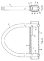
- the padlock according to FIGS. 1a and 1b comprises an approximately cuboid Lock body 10 and a shackle 12 with its shackle ends 14 is inserted into the lock body 10.
- the lock body 10 may include housing 28 as an integral part or at least be essentially formed by the housing 28.
- Locking arrangement 38 assigned. 1a and 1b is only one this locking arrangements 38 shown purely schematically. through a locking unit comprising a locking cylinder (not shown) locking elements of the locking arrangements 38 are perpendicular to the inserted temple ends 14 moved to the inserted temple ends 14 to lock and unlock the lock body 10.
- the buffer element 13 is a component a sandwich arrangement 21, which as further components of the Bracket 12 facing side wall 11 of the lock body 10 or its Housing 28 and a metal plate 29 comprises.
- the buffer element 13 and the metal plate 29 are inside the lock body 10 arranged, the buffer member 13 sandwiched between the metal plate 29 and the side wall 11 of the lock body 10 lies.
- the side of the lock body 10 facing the shackle is special endangered, since the lock body is often attempted in the event of a departure 10 knocking off the bracket by hitting this side.
- the the Sandwich arrangement comprising buffer element 13 protects this endangered one Side of the lock body 10, however, could in principle also on everyone other side and also be provided on several sides.
- Fig. 1b shows that the buffer element 13 and the metal plate 29 are the same Have width and over the entire width of the interior of the lock body 10 is available.
- a plurality of buffer elements can preferably also be provided, which are each assigned to one side of the lock body.
- the lock body is arranged in and through a buffer cage Protected from external influences on several sides at the same time.
- the Lock body can, for example, on each side with a buffer element be provided.
- a sandwich arrangement 21 is provided, which of the Bracket 12 facing side wall 11 of the lock body 10, a buffer element 13 and a metal plate 29 is formed.
- the buffer element 13 and the metal plate 29 are located outside the lock body 10. As a result, there is 10 more space within the lock body e.g. for the locking arrangements 38 available.
- the lock body or a housing of the lock body could also approximately U-shaped and with on its open side a sandwich arrangement of a buffer element and be provided with a metal plate.
- the buffer element lies doing so on the front edges of the perpendicular to the open side Side walls of the lock body or housing.
- the effective area the buffer element is comparatively small and is e.g. in the Area of a few square centimeters. With such an arrangement also achieved effective impact protection.
- the lock body can also have several separate ones Include housings, each of which is assigned at least one buffer element is.
Landscapes
- Connector Housings Or Holding Contact Members (AREA)
- Roof Covering Using Slabs Or Stiff Sheets (AREA)
- Purses, Travelling Bags, Baskets, Or Suitcases (AREA)
- Vibration Dampers (AREA)
- Materials For Photolithography (AREA)
- Surface Acoustic Wave Elements And Circuit Networks Thereof (AREA)
- Vehicle Body Suspensions (AREA)
- Soil Working Implements (AREA)
Description
- Fig. 1 - 2
- jeweils eine Ausführungsform eines erfindungsgemäßen Bügelschlosses, und zwar in zwei senkrecht zueinander stehenden Seitenansichten, und
- Fig. 3
- kein Ausführungsbeispiel der Erfindung, sondern lediglich ein das Verständnis der Erfindung erleichterndes Beispiel für ein Bügelschloss.
- 10
- Schloßkörper
- 11
- Seitenwand
- 12
- Bügel
- 13
- Pufferelement
- 14
- Bügelende
- 21
- Sandwichanordnung
- 28
- Gehäuse
- 29
- Schutzelement, Bestandteil, Metallplatte
- 38
- Verriegelungsanordnung
- 39
- Seitenwand
Claims (11)
- Bügelschloß mit einem Schloßkörper (10) und einem Bügel (12), der an seinen Bügelenden (14) mit dem Schloßkörper (10) koppelbar und im gekoppelten Zustand verriegelbar ist,
dadurch gekennzeichnet, daß der Schloßkörper (10) zur Verteilung von auf den Schloßkörper (10) aufgebrachten Schlagkräften mit wenigstens einem separaten Pufferelement (13) versehen ist, das sandwichartig zwischen zwei Plattenelementen (11, 29) angeordnet ist, wobei das Pufferelement (13) plattenförmig ausgebildet ist. - Bügelschloß nach Anspruch 1,
dadurch gekennzeichnet, daß das Pufferelement (13) aus Kunststoff hergestellt ist, und/oder in Schlagrichtung vor wenigstens einem von einem der Plattenelemente gebildeten Schutzelement (11, 29) angeordnet ist, das eine höhere Festigkeit aufweist als das Pufferelement (13). - Bügelschloß nach einem der vorhergehenden Ansprüche,
dadurch gekennzeichnet, daß das Pufferelement (13) mit zumindest einem Bereich des Schloßkörpers (10) in flächigem Kontakt steht, und/oder streifenförmig ausgebildet ist. - Bügelschloß nach einem der vorhergehenden Ansprüche,
dadurch gekennzeichnet, daß das Pufferelement (13) etwa parallel zu einer Seitenwand (11) des Schloßkörpers (10) verläuft, und/oder direkt an einer Seitenwand (11) des Schloßkörpers (10) anliegt. - Bügelschloß nach einem der vorhergehenden Ansprüche,
dadurch gekennzeichnet, daß sich das Pufferelement (13) von wenigstens einem der Plattenelemente (11, 29) hinsichtlich des Materials unterscheidet, wobei bevorzugt wenigstens ein, insbesondere jedes Plattenelement (11, 29) eine höhere Festigkeit aufweist als das Pufferelement (13) und vorzugsweise aus Metall hergestellt ist. - Bügelschloß nach einem der vorhergehenden Ansprüche,
dadurch gekennzeichnet, daß eine bevorzugt plattenförmige Seitenwand (11) des Schloßkörpers (10) Bestandteil der Sandwichanordnung (21) ist. - Bügelschloß nach einem der vorhergehenden Ansprüche,
dadurch gekennzeichnet, daß das Pufferelement (13) der dem Bügel (12) zugewandten Seitenwand (11) des Schloßkörpers (10) zugeordnet ist, und/oder
daß ausschließlich der dem Bügel (12) zugewandten Seitenwand (11) des Schloßkörpers (10) wenigstens ein Pufferelement (13) zugeordnet ist. - Bügelschloß nach einem der vorhergehenden Ansprüche,
dadurch gekennzeichnet, daß das Pufferelement (13) außerhalb des Schloßkörpers (10) angeordnet ist, oder daß das Pufferelement (13) innerhalb des Schloßkörpers (10) angeordnet ist, vorzugsweise zwischen einer Seitenwand (11) des Schloßkörpers (10) und einer im Schloßkörper (10) angeordneten Verriegelungsanordnung (38). - Bügelschloß nach einem der vorhergehenden Ansprüche,
dadurch gekennzeichnet, daß das Pufferelement (13) eine wirksame Fläche von wenigstens einigen Quadratzentimetern, insbesondere von zumindest etwa 2 cm2 aufweist, wobei bevorzugt die wirksame Fläche im Bereich von etwa 2 bis 10 cm2 liegt. - Bügelschloß nach einem der vorhergehenden Ansprüche,
dadurch gekennzeichnet, daß das Pufferelement (13) einem bevorzugt aus Metall hergestellten Gehäuse (28) des Schloßkörpers (10) zugeordnet ist, das vorzugsweise rohrförmig ausgebildet ist. - Bügelschloß nach einem der vorhergehenden Ansprüche,
dadurch gekennzeichnet, daß das Pufferelement (13) einer zumindest bereichsweise offenen Seite eines Gehäuses (28) des Schloßkörpers (10) zugeordnet ist und bevorzugt auf Stirnkanten von etwa senkrecht zur offenen Seite verlaufenden Seitenwänden des Gehäuses (28) aufliegt, wobei vorzugsweise das Gehäuse (28) etwa U-förmig ausgebildet ist.
Applications Claiming Priority (2)
| Application Number | Priority Date | Filing Date | Title |
|---|---|---|---|
| DE10026702 | 2000-05-30 | ||
| DE10026702A DE10026702A1 (de) | 2000-05-30 | 2000-05-30 | Bügelschloß |
Publications (2)
| Publication Number | Publication Date |
|---|---|
| EP1160404A1 EP1160404A1 (de) | 2001-12-05 |
| EP1160404B1 true EP1160404B1 (de) | 2004-12-08 |
Family
ID=7644043
Family Applications (1)
| Application Number | Title | Priority Date | Filing Date |
|---|---|---|---|
| EP01111065A Expired - Lifetime EP1160404B1 (de) | 2000-05-30 | 2001-05-08 | Bügelschloss |
Country Status (3)
| Country | Link |
|---|---|
| EP (1) | EP1160404B1 (de) |
| AT (1) | ATE284474T1 (de) |
| DE (2) | DE10026702A1 (de) |
Families Citing this family (1)
| Publication number | Priority date | Publication date | Assignee | Title |
|---|---|---|---|---|
| TWM450525U (zh) * | 2012-12-19 | 2013-04-11 | King Rack Ind Co Ltd | 攜車架之自行車鎖固結構 |
Family Cites Families (5)
| Publication number | Priority date | Publication date | Assignee | Title |
|---|---|---|---|---|
| US4576022A (en) * | 1984-08-29 | 1986-03-18 | Gamble William E | Object securing sleeve for padlock devices |
| DE4230813C2 (de) * | 1992-09-15 | 1995-09-28 | Winkhaus Fa August | Bügelschloß |
| DE4322989C2 (de) * | 1993-07-09 | 1996-10-10 | Winkhaus Fa August | Bügelschloß, insbesondere Langbügelschloß |
| SE9500650L (sv) * | 1995-02-22 | 1996-08-23 | Thule Ind Ab | Låsanordning |
| IL113802A0 (en) * | 1995-05-21 | 1995-08-31 | Mul T Lock Technologies Ltd | Improved spring loaded lock |
-
2000
- 2000-05-30 DE DE10026702A patent/DE10026702A1/de not_active Withdrawn
-
2001
- 2001-05-08 AT AT01111065T patent/ATE284474T1/de not_active IP Right Cessation
- 2001-05-08 DE DE2001504741 patent/DE50104741D1/de not_active Expired - Lifetime
- 2001-05-08 EP EP01111065A patent/EP1160404B1/de not_active Expired - Lifetime
Also Published As
| Publication number | Publication date |
|---|---|
| EP1160404A1 (de) | 2001-12-05 |
| DE10026702A1 (de) | 2001-12-06 |
| ATE284474T1 (de) | 2004-12-15 |
| DE50104741D1 (de) | 2005-01-13 |
Similar Documents
| Publication | Publication Date | Title |
|---|---|---|
| DE69309699T3 (de) | Sicherheitsbalken | |
| EP2083136A2 (de) | Zylinderschloss mit Plättchenzuhaltungen und Schlüssel für das Schloss | |
| DE102016012183A1 (de) | Crashstruktur für ein Fahrzeug | |
| EP3351712A1 (de) | Verriegelungsschelle zur sicherung eines tors an einem zaunpfosten | |
| DE10324521B4 (de) | Schmelzsicherung | |
| EP1160404B1 (de) | Bügelschloss | |
| EP4490373A1 (de) | BÜGELSCHLOSS MIT AUFSCHWEIßPANZERUNG | |
| EP0364936A2 (de) | Kraftfahrzeug-Türschloss | |
| DE10013376C1 (de) | Überrollschutzsystem | |
| EP1689959B1 (de) | Türinnenelement für eine kraftfahrzeugtür mit einer als einbruchssicherung dienenden abdeckung | |
| DE19526207A1 (de) | Stahltürblatt | |
| DE10120935A1 (de) | Seitenaufprallträger und Kraftfahrzeugtür | |
| EP1008469B1 (de) | Sicherungseinrichtung | |
| EP1368543B1 (de) | Oberflächen-entwässerungs-anordnung | |
| DE102015009085B3 (de) | Verriegelung für Möbelkoffer oder Frachtkontainer | |
| EP0567808A1 (de) | Schlüssel | |
| EP4461909B1 (de) | Verriegelungseinrichtung | |
| DE60025126T2 (de) | Schlossmechanismus für Fahrzeugtüre | |
| EP2708425B1 (de) | Elektrische Lenkverriegelung | |
| DE9013983U1 (de) | Kraftfahrzeug-Haubenschloß | |
| DE102015204943B4 (de) | Schließvorrichtung | |
| DE102016011514B3 (de) | Lenkzylinder-Sicherung | |
| DE202017000411U1 (de) | Einbruchssicherer Verkaufsautomat | |
| DE202016104078U1 (de) | Schließblechanordnung | |
| DE202016105117U1 (de) | Vorhängeschloss zum Sichern eines Schließelements |
Legal Events
| Date | Code | Title | Description |
|---|---|---|---|
| PUAI | Public reference made under article 153(3) epc to a published international application that has entered the european phase |
Free format text: ORIGINAL CODE: 0009012 |
|
| AK | Designated contracting states |
Kind code of ref document: A1 Designated state(s): AT BE CH CY DE DK ES FI FR GB GR IE IT LI LU MC NL PT SE TR |
|
| AX | Request for extension of the european patent |
Free format text: AL;LT;LV;MK;RO;SI |
|
| 17P | Request for examination filed |
Effective date: 20020130 |
|
| 17Q | First examination report despatched |
Effective date: 20020510 |
|
| AKX | Designation fees paid |
Free format text: AT BE CH CY DE DK ES FI FR GB GR IE IT LI LU MC NL PT SE TR |
|
| GRAP | Despatch of communication of intention to grant a patent |
Free format text: ORIGINAL CODE: EPIDOSNIGR1 |
|
| GRAS | Grant fee paid |
Free format text: ORIGINAL CODE: EPIDOSNIGR3 |
|
| GRAA | (expected) grant |
Free format text: ORIGINAL CODE: 0009210 |
|
| AK | Designated contracting states |
Kind code of ref document: B1 Designated state(s): AT BE CH CY DE DK ES FI FR GB GR IE IT LI LU MC NL PT SE TR |
|
| PG25 | Lapsed in a contracting state [announced via postgrant information from national office to epo] |
Ref country code: FR Free format text: LAPSE BECAUSE OF FAILURE TO SUBMIT A TRANSLATION OF THE DESCRIPTION OR TO PAY THE FEE WITHIN THE PRESCRIBED TIME-LIMIT Effective date: 20041208 Ref country code: NL Free format text: LAPSE BECAUSE OF FAILURE TO SUBMIT A TRANSLATION OF THE DESCRIPTION OR TO PAY THE FEE WITHIN THE PRESCRIBED TIME-LIMIT Effective date: 20041208 Ref country code: TR Free format text: LAPSE BECAUSE OF FAILURE TO SUBMIT A TRANSLATION OF THE DESCRIPTION OR TO PAY THE FEE WITHIN THE PRESCRIBED TIME-LIMIT Effective date: 20041208 Ref country code: FI Free format text: LAPSE BECAUSE OF FAILURE TO SUBMIT A TRANSLATION OF THE DESCRIPTION OR TO PAY THE FEE WITHIN THE PRESCRIBED TIME-LIMIT Effective date: 20041208 Ref country code: IE Free format text: LAPSE BECAUSE OF FAILURE TO SUBMIT A TRANSLATION OF THE DESCRIPTION OR TO PAY THE FEE WITHIN THE PRESCRIBED TIME-LIMIT Effective date: 20041208 Ref country code: GB Free format text: LAPSE BECAUSE OF FAILURE TO SUBMIT A TRANSLATION OF THE DESCRIPTION OR TO PAY THE FEE WITHIN THE PRESCRIBED TIME-LIMIT Effective date: 20041208 Ref country code: IT Free format text: LAPSE BECAUSE OF FAILURE TO SUBMIT A TRANSLATION OF THE DESCRIPTION OR TO PAY THE FEE WITHIN THE PRESCRIBED TIME-LIMIT;WARNING: LAPSES OF ITALIAN PATENTS WITH EFFECTIVE DATE BEFORE 2007 MAY HAVE OCCURRED AT ANY TIME BEFORE 2007. THE CORRECT EFFECTIVE DATE MAY BE DIFFERENT FROM THE ONE RECORDED. Effective date: 20041208 |
|
| REG | Reference to a national code |
Ref country code: GB Ref legal event code: FG4D Free format text: NOT ENGLISH |
|
| REG | Reference to a national code |
Ref country code: CH Ref legal event code: EP |
|
| REG | Reference to a national code |
Ref country code: IE Ref legal event code: FG4D Free format text: GERMAN |
|
| REF | Corresponds to: |
Ref document number: 50104741 Country of ref document: DE Date of ref document: 20050113 Kind code of ref document: P |
|
| PG25 | Lapsed in a contracting state [announced via postgrant information from national office to epo] |
Ref country code: SE Free format text: LAPSE BECAUSE OF FAILURE TO SUBMIT A TRANSLATION OF THE DESCRIPTION OR TO PAY THE FEE WITHIN THE PRESCRIBED TIME-LIMIT Effective date: 20050308 Ref country code: GR Free format text: LAPSE BECAUSE OF FAILURE TO SUBMIT A TRANSLATION OF THE DESCRIPTION OR TO PAY THE FEE WITHIN THE PRESCRIBED TIME-LIMIT Effective date: 20050308 Ref country code: DK Free format text: LAPSE BECAUSE OF FAILURE TO SUBMIT A TRANSLATION OF THE DESCRIPTION OR TO PAY THE FEE WITHIN THE PRESCRIBED TIME-LIMIT Effective date: 20050308 |
|
| PG25 | Lapsed in a contracting state [announced via postgrant information from national office to epo] |
Ref country code: ES Free format text: LAPSE BECAUSE OF FAILURE TO SUBMIT A TRANSLATION OF THE DESCRIPTION OR TO PAY THE FEE WITHIN THE PRESCRIBED TIME-LIMIT Effective date: 20050319 |
|
| PG25 | Lapsed in a contracting state [announced via postgrant information from national office to epo] |
Ref country code: LU Free format text: LAPSE BECAUSE OF NON-PAYMENT OF DUE FEES Effective date: 20050508 Ref country code: CY Free format text: LAPSE BECAUSE OF FAILURE TO SUBMIT A TRANSLATION OF THE DESCRIPTION OR TO PAY THE FEE WITHIN THE PRESCRIBED TIME-LIMIT Effective date: 20050508 Ref country code: AT Free format text: LAPSE BECAUSE OF NON-PAYMENT OF DUE FEES Effective date: 20050508 |
|
| PG25 | Lapsed in a contracting state [announced via postgrant information from national office to epo] |
Ref country code: CH Free format text: LAPSE BECAUSE OF NON-PAYMENT OF DUE FEES Effective date: 20050531 Ref country code: BE Free format text: LAPSE BECAUSE OF NON-PAYMENT OF DUE FEES Effective date: 20050531 Ref country code: MC Free format text: LAPSE BECAUSE OF NON-PAYMENT OF DUE FEES Effective date: 20050531 Ref country code: LI Free format text: LAPSE BECAUSE OF NON-PAYMENT OF DUE FEES Effective date: 20050531 |
|
| NLV1 | Nl: lapsed or annulled due to failure to fulfill the requirements of art. 29p and 29m of the patents act | ||
| GBV | Gb: ep patent (uk) treated as always having been void in accordance with gb section 77(7)/1977 [no translation filed] |
Effective date: 20041208 |
|
| REG | Reference to a national code |
Ref country code: IE Ref legal event code: FD4D |
|
| PLBE | No opposition filed within time limit |
Free format text: ORIGINAL CODE: 0009261 |
|
| STAA | Information on the status of an ep patent application or granted ep patent |
Free format text: STATUS: NO OPPOSITION FILED WITHIN TIME LIMIT |
|
| 26N | No opposition filed |
Effective date: 20050909 |
|
| BERE | Be: lapsed |
Owner name: ABUS AUGUST BREMICKER SOHNE K.G. Effective date: 20050531 |
|
| REG | Reference to a national code |
Ref country code: CH Ref legal event code: PL |
|
| EN | Fr: translation not filed | ||
| BERE | Be: lapsed |
Owner name: *ABUS AUGUST BREMICKER SOHNE K.G. Effective date: 20050531 |
|
| PG25 | Lapsed in a contracting state [announced via postgrant information from national office to epo] |
Ref country code: PT Free format text: LAPSE BECAUSE OF NON-PAYMENT OF DUE FEES Effective date: 20050508 |
|
| PGFP | Annual fee paid to national office [announced via postgrant information from national office to epo] |
Ref country code: DE Payment date: 20150730 Year of fee payment: 15 |
|
| REG | Reference to a national code |
Ref country code: DE Ref legal event code: R119 Ref document number: 50104741 Country of ref document: DE |
|
| PG25 | Lapsed in a contracting state [announced via postgrant information from national office to epo] |
Ref country code: DE Free format text: LAPSE BECAUSE OF NON-PAYMENT OF DUE FEES Effective date: 20161201 |