EP1160430A2 - Aufgeladene Brennkraftmaschine mit verbessertem Kurbelmechanismus - Google Patents
Aufgeladene Brennkraftmaschine mit verbessertem Kurbelmechanismus Download PDFInfo
- Publication number
- EP1160430A2 EP1160430A2 EP01113292A EP01113292A EP1160430A2 EP 1160430 A2 EP1160430 A2 EP 1160430A2 EP 01113292 A EP01113292 A EP 01113292A EP 01113292 A EP01113292 A EP 01113292A EP 1160430 A2 EP1160430 A2 EP 1160430A2
- Authority
- EP
- European Patent Office
- Prior art keywords
- piston
- link
- internal combustion
- crank mechanism
- opposite ends
- Prior art date
- Legal status (The legal status is an assumption and is not a legal conclusion. Google has not performed a legal analysis and makes no representation as to the accuracy of the status listed.)
- Granted
Links
- 230000007246 mechanism Effects 0.000 title claims abstract description 51
- 238000002485 combustion reaction Methods 0.000 title claims abstract description 42
- 230000006835 compression Effects 0.000 claims abstract description 46
- 238000007906 compression Methods 0.000 claims abstract description 46
- 238000000034 method Methods 0.000 description 8
- 230000008569 process Effects 0.000 description 8
- 230000001133 acceleration Effects 0.000 description 7
- 239000000446 fuel Substances 0.000 description 5
- 230000001965 increasing effect Effects 0.000 description 4
- 230000006870 function Effects 0.000 description 2
- 239000000203 mixture Substances 0.000 description 2
- 230000004044 response Effects 0.000 description 2
- 238000006243 chemical reaction Methods 0.000 description 1
- 238000004891 communication Methods 0.000 description 1
- 230000000694 effects Effects 0.000 description 1
- 230000002708 enhancing effect Effects 0.000 description 1
- 239000000463 material Substances 0.000 description 1
- 238000012986 modification Methods 0.000 description 1
- 230000004048 modification Effects 0.000 description 1
Images

Classifications
-
- F—MECHANICAL ENGINEERING; LIGHTING; HEATING; WEAPONS; BLASTING
- F02—COMBUSTION ENGINES; HOT-GAS OR COMBUSTION-PRODUCT ENGINE PLANTS
- F02B—INTERNAL-COMBUSTION PISTON ENGINES; COMBUSTION ENGINES IN GENERAL
- F02B67/00—Engines characterised by the arrangement of auxiliary apparatus not being otherwise provided for, e.g. the apparatus having different functions; Driving auxiliary apparatus from engines, not otherwise provided for
-
- F—MECHANICAL ENGINEERING; LIGHTING; HEATING; WEAPONS; BLASTING
- F02—COMBUSTION ENGINES; HOT-GAS OR COMBUSTION-PRODUCT ENGINE PLANTS
- F02B—INTERNAL-COMBUSTION PISTON ENGINES; COMBUSTION ENGINES IN GENERAL
- F02B75/00—Other engines
- F02B75/04—Engines with variable distances between pistons at top dead-centre positions and cylinder heads
- F02B75/048—Engines with variable distances between pistons at top dead-centre positions and cylinder heads by means of a variable crank stroke length
Definitions
- the present invention relates to an internal combustion engine with a supercharger disposed in an intake system and more particularly to a supercharged internal combustion engine of a reciprocating piston type having an improved piston crank mechanism which can optimize the piston speed when the engine is in a supercharged condition and can vary the compression ratio in accordance with an operating condition of the engine.
- variable compression ratio mechanism variably controls the compression ratio through a variable control of the volume of a chamber in communication with an engine cylinder, which is attained by varying a position of a piston disposed in the chamber.
- the burn duration becomes longer, the combustion is not completed within a crank angle range (the first half of the expansion stroke) where the heat of the combustion can be effectively converted to the output of the engine. Accordingly, the heat generated at the latter period of the combustion is not effectively converted to the output of the engine but is used only for increasing the temperature of the exhaust gas, thus lowering the thermal efficiency of the engine and causing a high exhaust gas temperature at high load.
- the present invention provides an internal combustion engine comprising a piston reciprocatively movable within a cylinder of the engine, a piston crank mechanism for converting reciprocative motion of the piston to rotation of a crank shaft, and a supercharger for supercharging the cylinder, wherein the piston crank mechanism connects between the piston and the crankshaft so as to cause the piston to move at a speed which is lower around a top dead center of the piston and higher around a bottom dead center of the piston as compared with respective corresponding speeds attained by a comparable single-link type piston crank mechanism.
- the double-link type piston crank mechanism is constructed to attain an optimum piston speed when the engine is in a supercharged condition, which will be understood when the description proceeds further.
- the double-link type piston crank mechanism has a function of varying a compression ratio of the engine, i.e., also functions as a variable compression ratio mechanism.
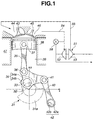
- the piston crank mechanism includes crank shaft 31 having a plurality of journal portions 32, a plurality of crank pins 33 and a plurality of counter weight portions 31a.
- main bearings (not shown) installed on cylinder block 47 constituting part of a main body of the engine are rotatably supported journal portions 32.
- Crank pins 33 are offset from journal portions 32 by a predetermined amount.
- To crank pins 33 are swingably or pivotally connected lower links 34 serving as second links.
- Lower link 34 is nearly T-shaped and includes main body 34a and cap 34b which are separable. Nearly at a central portion of lower link 34 and between main body 34a and cap 34b is formed a connecting hole in which crank pin 33 is fitted.
- Upper link 35 serving as a first link is pivotally connected at a lower end to one end of lower link 34 by means of connecting pin 36 and at an upper end to piston 38 by means of piston pin 37.
- Piston 38 is subjected to a combustion pressure and reciprocates within cylinder 39 of cylinder block 47.
- intake valve 43 that opens and closes intake port 44 in a timed relation to revolution of crankshaft 31 and exhaust valve 45 that opens and closes exhaust port 46 in timed relation to revolution of crankshaft 31.
- Control link 40 that serves as a third link is pivotally connected at an upper end to the other end of lower link 34 by means of connecting pin 41 and at a lower end to the engine main body such as cylinder block 47 by way of control shaft 42. More specifically, control shaft 42 has larger diameter portion 42a to which the lower end of control link 40 is pivotally connected. Control shaft 42 further has smaller diameter portion 42b which is eccentric with larger diameter portion 42a and at which it is pivotally supported on the engine main body. Control shaft 42 and the engine main body constitute a variable pivot device for varying a pivotal position at which control link 40 or third link is pivotally connected to the engine main body.
- Rotational position of control shaft 42 is controlled by a control system.
- the control system is constructed so as to be capable of holding control shaft 42 at a desired rotational position against a reaction force which is applied to control shaft 42 from control link 40.
- the control system will be described more in detail hereinlater.
- turbocharger 51 which serves as a supercharger.
- Turbocharger 51 includes turbine 52 disposed in exhaust passage 54 and compressor 53 disposed in intake passage 55 and coaxially with turbine 52.
- exhaust bypass valve 56 In order to control the supercharging pressure in accordance with the operating conditions of the engine, there is provided exhaust bypass valve 56 for allowing part of the exhaust gas to bypass turbine 52.
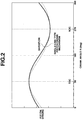
- the solid line curve in Fig. 2 represents the piston stroke characteristics of the double-link type piston crank mechanism in Fig. 1.
- the dotted line curve represents the piston stroke characteristics of an ordinary single-link type piston crank mechanism, i.e., a piston crank mechanism wherein a piston pin and a crank pin is connected by a single link (connecting rod).
- BDC bottom dead center
- the piston speed can be made smaller around the TDC and larger around the BDC by adjusting the interrelation or connections of the links, without varying the height of the engine.
- the piston crank mechanism of Fig. 1 which is structured as described above, the piston speed is smaller around the TDC and larger around the BDC as compared with respective corresponding piston speeds attained by a comparable single-link type piston crank mechanism.
- Fig. 2 shows the piston stroke characteristics of the double-link type and single-link type piston crank mechanisms on the condition that the stroke of the piston and the height of the engine are nearly the same in the two mechanisms.
- the solid line curve in Fig. 2 represents an example of piston stroke characteristics under a low compression ratio condition which is used at high supercharging operation (high load operation).
- the piston speed under a high compression ratio condition is a little larger adjacent the TDC and a little smaller adjacent the BDC than that shown in Fig. 2.
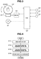
- the control system shown in Fig. 3 includes an electric motor 100 which is drivingly connected to gearing 102 for controlling the rotation angle of control shaft 42 by way of gearing 102.
- gearing 101 includes a worm (no numeral) connected to a rotation shaft of motor 100 and a worm wheel (no numeral) meshed with the worm and drivingly connected to control shaft 42.
- the rotation angle of control shaft 42 is detected by rotation angle sensor 102.
- the supercharging pressure in an intake system, which is produced by turbo charger 51, is detected by supercharging pressure sensor 122.
- Motor 100 is controlled by an engine control module (ECM) 123.
- ECM engine control module
- Inputted to engine control module 123 are an accelerator pedal opening degree signal from accelerator pedal opening degree sensor 120 and an engine speed signal from engine speed sensor 121. On the basis of those signals, engine control module 123 calculates a target rotation angle of control shaft 42 and a target supercharging pressure and supplies control signals representative of a calculated target rotation angle and a calculated target supercharging pressure to motor 100 and exhaust bypass valve 56.
- Fig. 4 is a flowchart showing a process which is executed in engine control module 123 for calculating a target supercharging pressure and a target control shaft rotation angle. This process is executed repeatedly every predetermined time. Firstly, in step S101, acceleration pedal opening degree (equivalent of engine load) APS, engine speed NE and actual super charging pressure SCP at this time are read on the basis of the output of acceleration pedal opening degree sensor 120, the output of engine speed sensor 121 and the output of supercharging sensor 122, respectively.
- acceleration pedal opening degree equivalent of engine load
- NE engine speed NE
- SCP actual super charging pressure
- step S102 target supercharging pressure tSCP is calculated on the basis of acceleration pedal opening degree APS and engine speed NE. Specifically, a corresponding value to target supercharging pressure tSCP is looked up in a control map (not shown) in which target supercharging pressure tSCP is stored in a way as to correspond to acceleration pedal opening degree APS and engine speed NE.
- the control map is set to have such characteristics that the supercharging pressure becomes larger as the load (APS) and engine speed become higher.
- step S103 target rotation angle tCA of control shaft 42 of the variable compression ratio mechanism is calculated on the basis of actual supercharging pressure SCP and engine speed NE. Specifically, a corresponding value to target rotation angle tCA is looked up in a control map (not shown) in which target rotation angle tCA is stored in a way as to correspond to actual supercharging pressure SCP and engine speed NE.
- the control map is constructed so as to have such characteristics that the compression ratio becomes highest within the limits that does not cause knocking. Accordingly, a high compression ratio is obtained under a low supercharging pressure condition, and the compression ratio becomes lower as the supercharging pressure becomes higher.
- step S104 calculated target supercharging pressure tSCP and calculated target rotation angle tCA are stored in a memory in engine control module 123.
- the process in Fig. 4 is for carrying out only calculation of various target values. Actual supercharging pressure control and actual rotation angle control are performed by a supercharging pressure control process and a compression ratio control process which are not shown.
- a feedback correction opening degree of exhaust bypass valve 56 corresponding to a difference between latest target supercharging pressure tSCP and latest actual supercharging pressure SCP which are stored in the memory is calculated, and a control signal representative of the correction opening degree is supplied to exhaust bypass valve 56.
- the correction opening degree is given so as to increase the opening degree of exhaust bypass valve 56 when tSCP > SCP and decrease the opening degree when tSCP ⁇ SCP.
- a feedback control signal corresponding to the difference between latest target rotation angle tCA and an actual rotation angle (which is detected by rotation angle sensor 102) is formed and supplied to motor 100.
- Fig. 5 shows an example of a time chart of a supercharging control and a compression ratio control at the time of acceleration. As shown, as acceleration pedal opening degree APS increases, target supercharging pressure tSCP becomes higher and a little later actual supercharging pressure SCP becomes higher. In response to increase of the actual supercharging pressure, the compression ratio is lowered to avoid knocking.
- the piston crank mechanism is constructed so that the speed of the piston around the top dead center when the compression ratio is relatively low is smaller than that when the compression ratio is relatively high. This is effective for further enhancing or improving the effect of the present invention since the piston speed can be lower around the TDC when the compression ratio is low, i.e., at high load operation.
Landscapes
- Engineering & Computer Science (AREA)
- Chemical & Material Sciences (AREA)
- Combustion & Propulsion (AREA)
- Mechanical Engineering (AREA)
- General Engineering & Computer Science (AREA)
- Output Control And Ontrol Of Special Type Engine (AREA)
- Supercharger (AREA)
- Combustion Methods Of Internal-Combustion Engines (AREA)
- Combined Controls Of Internal Combustion Engines (AREA)
- Transmission Devices (AREA)
Applications Claiming Priority (2)
| Application Number | Priority Date | Filing Date | Title |
|---|---|---|---|
| JP2000165528A JP3968957B2 (ja) | 2000-06-02 | 2000-06-02 | 内燃機関 |
| JP2000165528 | 2000-06-02 |
Publications (3)
| Publication Number | Publication Date |
|---|---|
| EP1160430A2 true EP1160430A2 (de) | 2001-12-05 |
| EP1160430A3 EP1160430A3 (de) | 2002-12-11 |
| EP1160430B1 EP1160430B1 (de) | 2007-11-28 |
Family
ID=18668991
Family Applications (1)
| Application Number | Title | Priority Date | Filing Date |
|---|---|---|---|
| EP01113292A Expired - Lifetime EP1160430B1 (de) | 2000-06-02 | 2001-05-31 | Aufgeladene Brennkraftmaschine mit verbessertem Kurbelmechanismus |
Country Status (4)
| Country | Link |
|---|---|
| US (1) | US6516757B2 (de) |
| EP (1) | EP1160430B1 (de) |
| JP (1) | JP3968957B2 (de) |
| DE (1) | DE60131598T2 (de) |
Cited By (8)
| Publication number | Priority date | Publication date | Assignee | Title |
|---|---|---|---|---|
| EP1380739A1 (de) * | 2002-07-11 | 2004-01-14 | Nissan Motor Co., Ltd. | Gerät und Verfahren zur Verdichtungsverhältnisregelung einer fremdgezündeten Brennkraftmaschine |
| WO2004053345A1 (en) * | 2002-12-11 | 2004-06-24 | Dapomot Oy | Crank mechanism of combustion engine___________________ |
| WO2006112256A1 (en) * | 2005-04-14 | 2006-10-26 | Toyota Jidosha Kabushiki Kaisha | Variable compression ratio internal combustion engine |
| EP1318286A3 (de) * | 2001-12-06 | 2008-03-26 | Nissan Motor Co., Ltd. | Steuersystem für eine Brennkraftmaschine mit variablem Verdichtungsverhältnis und Steuersystem eines Abgasrückführungssystems |
| EP1602812A3 (de) * | 2004-06-04 | 2009-02-04 | Nissan Motor Company, Limited | Kontrollieren einer Brennkraftmaschine mit Kolben Kurbelmechanismus mit Multi-Gelenkgetriebe |
| EP2960471A4 (de) * | 2013-02-22 | 2016-07-13 | Nissan Motor | Vorrichtung und verfahren zur steuerung eines verbrennungsmotors |
| CN104603435B (zh) * | 2013-03-07 | 2016-11-16 | 日立汽车系统株式会社 | 发动机的控制装置以及控制方法 |
| CN110159426A (zh) * | 2019-06-28 | 2019-08-23 | 长城汽车股份有限公司 | 发动机的装配方法以及发动机 |
Families Citing this family (19)
| Publication number | Priority date | Publication date | Assignee | Title |
|---|---|---|---|---|
| JP3994783B2 (ja) * | 2002-04-19 | 2007-10-24 | 日産自動車株式会社 | 内燃機関の制御装置 |
| US7043349B2 (en) * | 2002-04-25 | 2006-05-09 | Ford Global Technologies, Llc | Method and system for inferring exhaust temperature of a variable compression ratio engine |
| JP4096700B2 (ja) * | 2002-11-05 | 2008-06-04 | 日産自動車株式会社 | 内燃機関の可変圧縮比装置 |
| US6976456B2 (en) * | 2003-06-26 | 2005-12-20 | Ford Global Technologies, Llc | Connecting rod |
| JP2006183460A (ja) * | 2004-12-24 | 2006-07-13 | Nissan Motor Co Ltd | ブレイトンサイクル機関 |
| JP2007002795A (ja) * | 2005-06-27 | 2007-01-11 | Nissan Motor Co Ltd | 筒内直接噴射式火花点火内燃機関の制御装置 |
| JP4882912B2 (ja) * | 2007-08-10 | 2012-02-22 | 日産自動車株式会社 | 可変圧縮比内燃機関 |
| JP5029290B2 (ja) * | 2007-10-29 | 2012-09-19 | 日産自動車株式会社 | 可変圧縮比エンジン |
| JP4968031B2 (ja) * | 2007-12-06 | 2012-07-04 | 日産自動車株式会社 | エンジン |
| DE102010032490A1 (de) * | 2010-07-28 | 2012-02-02 | Daimler Ag | Hubkolbenmaschine, insbesondere für einen Kraftwagen, sowie Verfahren zum Betreiben einer solchen Hubkolbenmaschine |
| JP5854152B2 (ja) * | 2012-10-09 | 2016-02-09 | トヨタ自動車株式会社 | 可変圧縮比機構を備える内燃機関 |
| KR101518933B1 (ko) | 2013-12-03 | 2015-05-12 | 현대자동차 주식회사 | 터보차저 제어 방법 |
| KR101490959B1 (ko) * | 2013-12-12 | 2015-02-12 | 현대자동차 주식회사 | 터보 차저 제어 방법 |
| JP6408419B2 (ja) * | 2015-04-17 | 2018-10-17 | 日立オートモティブシステムズ株式会社 | 内燃機関の圧縮比調整装置 |
| RU2670343C1 (ru) * | 2015-07-02 | 2018-10-22 | Ниссан Мотор Ко., Лтд. | Способ управления и устройство управления для двигателя внутреннего сгорания |
| US10344684B2 (en) * | 2015-08-20 | 2019-07-09 | Nissan Motor Co., Ltd. | Control device of engine and control method of engine |
| JP6494502B2 (ja) * | 2015-12-24 | 2019-04-03 | 日立オートモティブシステムズ株式会社 | 内燃機関のピストンストローク調整装置 |
| DE102016011392A1 (de) * | 2016-09-21 | 2018-03-22 | GM Global Technology Operations, LLC (n.d. Ges. d. Staates Delaware) | Brennkraftmaschine |
| US10428863B2 (en) | 2017-06-21 | 2019-10-01 | GM Global Technology Operations LLC | Variable compression ratio engine |
Family Cites Families (7)
| Publication number | Priority date | Publication date | Assignee | Title |
|---|---|---|---|---|
| US2259176A (en) * | 1939-10-02 | 1941-10-14 | Earl H Pitney | Internal combustion engine |
| US3029594A (en) * | 1960-11-10 | 1962-04-17 | Miller Ralph | Matched turbocharger and engine |
| DE2734715A1 (de) * | 1977-08-02 | 1979-02-22 | Scherf Geb Kindermann Eva | Hubkolbenmotor |
| JPH073201B2 (ja) | 1985-10-01 | 1995-01-18 | トヨタ自動車株式会社 | 可変圧縮比装置付機械式過給エンジン |
| JPH0364647A (ja) * | 1989-08-02 | 1991-03-20 | Mazda Motor Corp | ターボ過給機付エンジンの可変圧縮比制御装置 |
| JP4248036B2 (ja) * | 1997-02-10 | 2009-04-02 | 日産自動車株式会社 | ターボ過給機付内燃機関の吸気弁制御装置および制御方法 |
| GB9719536D0 (en) * | 1997-09-12 | 1997-11-19 | Broadsuper Ltd | Internal combustion engines |
-
2000
- 2000-06-02 JP JP2000165528A patent/JP3968957B2/ja not_active Expired - Lifetime
-
2001
- 2001-05-31 EP EP01113292A patent/EP1160430B1/de not_active Expired - Lifetime
- 2001-05-31 DE DE60131598T patent/DE60131598T2/de not_active Expired - Lifetime
- 2001-06-01 US US09/870,741 patent/US6516757B2/en not_active Expired - Lifetime
Cited By (11)
| Publication number | Priority date | Publication date | Assignee | Title |
|---|---|---|---|---|
| EP1318286A3 (de) * | 2001-12-06 | 2008-03-26 | Nissan Motor Co., Ltd. | Steuersystem für eine Brennkraftmaschine mit variablem Verdichtungsverhältnis und Steuersystem eines Abgasrückführungssystems |
| EP1380739A1 (de) * | 2002-07-11 | 2004-01-14 | Nissan Motor Co., Ltd. | Gerät und Verfahren zur Verdichtungsverhältnisregelung einer fremdgezündeten Brennkraftmaschine |
| US6915766B2 (en) | 2002-07-11 | 2005-07-12 | Nissan Motor Co., Ltd. | Compression ratio controlling apparatus and method for spark-ignited internal combustion engine |
| WO2004053345A1 (en) * | 2002-12-11 | 2004-06-24 | Dapomot Oy | Crank mechanism of combustion engine___________________ |
| EP1602812A3 (de) * | 2004-06-04 | 2009-02-04 | Nissan Motor Company, Limited | Kontrollieren einer Brennkraftmaschine mit Kolben Kurbelmechanismus mit Multi-Gelenkgetriebe |
| WO2006112256A1 (en) * | 2005-04-14 | 2006-10-26 | Toyota Jidosha Kabushiki Kaisha | Variable compression ratio internal combustion engine |
| US7627417B2 (en) | 2005-04-14 | 2009-12-01 | Toyota Jidosha Kabushiki Kaisha | Variable compression ratio internal combustion engine |
| EP2960471A4 (de) * | 2013-02-22 | 2016-07-13 | Nissan Motor | Vorrichtung und verfahren zur steuerung eines verbrennungsmotors |
| US9909520B2 (en) | 2013-02-22 | 2018-03-06 | Nissan Motor Co., Ltd. | Device and method for controlling internal combustion engine |
| CN104603435B (zh) * | 2013-03-07 | 2016-11-16 | 日立汽车系统株式会社 | 发动机的控制装置以及控制方法 |
| CN110159426A (zh) * | 2019-06-28 | 2019-08-23 | 长城汽车股份有限公司 | 发动机的装配方法以及发动机 |
Also Published As
| Publication number | Publication date |
|---|---|
| US6516757B2 (en) | 2003-02-11 |
| JP2001342859A (ja) | 2001-12-14 |
| JP3968957B2 (ja) | 2007-08-29 |
| DE60131598T2 (de) | 2008-03-13 |
| DE60131598D1 (de) | 2008-01-10 |
| EP1160430A3 (de) | 2002-12-11 |
| EP1160430B1 (de) | 2007-11-28 |
| US20010047778A1 (en) | 2001-12-06 |
Similar Documents
| Publication | Publication Date | Title |
|---|---|---|
| US6516757B2 (en) | Internal combustion engine with a supercharger and an improved piston crank mechanism | |
| US6990934B2 (en) | Internal combustion engine having variable compression ratio mechanism and control method therefor | |
| US6202623B1 (en) | Internal combustion engines | |
| JP4134830B2 (ja) | 内燃機関の圧縮比制御装置 | |
| CN103874839B (zh) | 对内燃机转速进行控制的装置以及方法 | |
| US7100547B2 (en) | Intake-air control system for engine | |
| CN104321517B (zh) | 内燃机的控制装置以及控制方法 | |
| Clenci et al. | Some aspects concerning the combination of downsizing with turbocharging, variable compression ratio, and variable intake valve lift | |
| JP4135394B2 (ja) | 内燃機関の制御装置 | |
| JP2005069027A (ja) | 内燃機関の可変圧縮比機構 | |
| CN110730861B (zh) | 内燃机的控制方法及控制装置 | |
| JP4596726B2 (ja) | 内燃機関の制御装置 | |
| JP7324657B2 (ja) | 内燃機関制御方法及び内燃機関制御装置 | |
| JP4415464B2 (ja) | 可変圧縮比装置付ターボ過給内燃機関 | |
| JP2005163695A (ja) | 内燃機関の圧縮比制御装置 | |
| JP4400116B2 (ja) | 可変圧縮比機構付き内燃機関の点火制御装置 | |
| JP2004156464A (ja) | 内燃機関の圧縮比制御装置 | |
| JP4968031B2 (ja) | エンジン | |
| JP6870350B2 (ja) | 内燃機関の制御装置 | |
| JP4241351B2 (ja) | 可変圧縮比内燃機関の制御装置及び制御方法 | |
| JP4155019B2 (ja) | エンジンの吸気制御装置 | |
| JP5114077B2 (ja) | 過給式エンジン | |
| JP2011247177A (ja) | 可変圧縮比内燃機関の制御装置 | |
| JPH06137176A (ja) | 内燃機関における排気量及び圧縮比の可変構造 | |
| CN113864068A (zh) | 可变压缩比发动机控制策略 |
Legal Events
| Date | Code | Title | Description |
|---|---|---|---|
| PUAI | Public reference made under article 153(3) epc to a published international application that has entered the european phase |
Free format text: ORIGINAL CODE: 0009012 |
|
| 17P | Request for examination filed |
Effective date: 20010531 |
|
| AK | Designated contracting states |
Kind code of ref document: A2 Designated state(s): AT BE CH CY DE DK ES FI FR GB GR IE IT LI LU MC NL PT SE TR |
|
| AX | Request for extension of the european patent |
Free format text: AL;LT;LV;MK;RO;SI |
|
| PUAL | Search report despatched |
Free format text: ORIGINAL CODE: 0009013 |
|
| AK | Designated contracting states |
Kind code of ref document: A3 Designated state(s): AT BE CH CY DE DK ES FI FR GB GR IE IT LI LU MC NL PT SE TR |
|
| AX | Request for extension of the european patent |
Free format text: AL;LT;LV;MK;RO;SI |
|
| AKX | Designation fees paid |
Designated state(s): DE FR GB |
|
| 17Q | First examination report despatched |
Effective date: 20061026 |
|
| GRAP | Despatch of communication of intention to grant a patent |
Free format text: ORIGINAL CODE: EPIDOSNIGR1 |
|
| GRAS | Grant fee paid |
Free format text: ORIGINAL CODE: EPIDOSNIGR3 |
|
| GRAA | (expected) grant |
Free format text: ORIGINAL CODE: 0009210 |
|
| AK | Designated contracting states |
Kind code of ref document: B1 Designated state(s): DE FR GB |
|
| REG | Reference to a national code |
Ref country code: GB Ref legal event code: FG4D |
|
| REF | Corresponds to: |
Ref document number: 60131598 Country of ref document: DE Date of ref document: 20080110 Kind code of ref document: P |
|
| ET | Fr: translation filed | ||
| PLBE | No opposition filed within time limit |
Free format text: ORIGINAL CODE: 0009261 |
|
| STAA | Information on the status of an ep patent application or granted ep patent |
Free format text: STATUS: NO OPPOSITION FILED WITHIN TIME LIMIT |
|
| 26N | No opposition filed |
Effective date: 20080829 |
|
| REG | Reference to a national code |
Ref country code: FR Ref legal event code: PLFP Year of fee payment: 16 |
|
| REG | Reference to a national code |
Ref country code: FR Ref legal event code: PLFP Year of fee payment: 17 |
|
| REG | Reference to a national code |
Ref country code: FR Ref legal event code: PLFP Year of fee payment: 18 |
|
| PGFP | Annual fee paid to national office [announced via postgrant information from national office to epo] |
Ref country code: FR Payment date: 20200414 Year of fee payment: 20 Ref country code: DE Payment date: 20200519 Year of fee payment: 20 |
|
| PGFP | Annual fee paid to national office [announced via postgrant information from national office to epo] |
Ref country code: GB Payment date: 20200520 Year of fee payment: 20 |
|
| REG | Reference to a national code |
Ref country code: DE Ref legal event code: R071 Ref document number: 60131598 Country of ref document: DE |
|
| REG | Reference to a national code |
Ref country code: GB Ref legal event code: PE20 Expiry date: 20210530 |
|
| PG25 | Lapsed in a contracting state [announced via postgrant information from national office to epo] |
Ref country code: GB Free format text: LAPSE BECAUSE OF EXPIRATION OF PROTECTION Effective date: 20210530 |