EP1160459A2 - Vakuumpumpe - Google Patents
Vakuumpumpe Download PDFInfo
- Publication number
- EP1160459A2 EP1160459A2 EP01304799A EP01304799A EP1160459A2 EP 1160459 A2 EP1160459 A2 EP 1160459A2 EP 01304799 A EP01304799 A EP 01304799A EP 01304799 A EP01304799 A EP 01304799A EP 1160459 A2 EP1160459 A2 EP 1160459A2
- Authority
- EP
- European Patent Office
- Prior art keywords
- section
- vacuum pump
- holweck
- compound vacuum
- separating
- Prior art date
- Legal status (The legal status is an assumption and is not a legal conclusion. Google has not performed a legal analysis and makes no representation as to the accuracy of the status listed.)
- Withdrawn
Links
- 239000000428 dust Substances 0.000 claims abstract description 20
- 230000001172 regenerating effect Effects 0.000 claims abstract description 19
- 150000001875 compounds Chemical class 0.000 claims abstract description 13
- 230000004888 barrier function Effects 0.000 claims abstract description 4
- 238000011144 upstream manufacturing Methods 0.000 claims description 2
- 238000000034 method Methods 0.000 abstract description 3
- 239000002245 particle Substances 0.000 abstract description 2
- 239000007789 gas Substances 0.000 description 4
- 230000003628 erosive effect Effects 0.000 description 1
- 230000002401 inhibitory effect Effects 0.000 description 1
- 238000005086 pumping Methods 0.000 description 1
- 238000009987 spinning Methods 0.000 description 1
Images
Classifications
-
- F—MECHANICAL ENGINEERING; LIGHTING; HEATING; WEAPONS; BLASTING
- F04—POSITIVE - DISPLACEMENT MACHINES FOR LIQUIDS; PUMPS FOR LIQUIDS OR ELASTIC FLUIDS
- F04D—NON-POSITIVE-DISPLACEMENT PUMPS
- F04D29/00—Details, component parts, or accessories
- F04D29/70—Suction grids; Strainers; Dust separation; Cleaning
-
- F—MECHANICAL ENGINEERING; LIGHTING; HEATING; WEAPONS; BLASTING
- F04—POSITIVE - DISPLACEMENT MACHINES FOR LIQUIDS; PUMPS FOR LIQUIDS OR ELASTIC FLUIDS
- F04D—NON-POSITIVE-DISPLACEMENT PUMPS
- F04D17/00—Radial-flow pumps, e.g. centrifugal pumps; Helico-centrifugal pumps
- F04D17/08—Centrifugal pumps
- F04D17/16—Centrifugal pumps for displacing without appreciable compression
- F04D17/168—Pumps specially adapted to produce a vacuum
-
- F—MECHANICAL ENGINEERING; LIGHTING; HEATING; WEAPONS; BLASTING
- F04—POSITIVE - DISPLACEMENT MACHINES FOR LIQUIDS; PUMPS FOR LIQUIDS OR ELASTIC FLUIDS
- F04D—NON-POSITIVE-DISPLACEMENT PUMPS
- F04D19/00—Axial-flow pumps
- F04D19/02—Multi-stage pumps
- F04D19/04—Multi-stage pumps specially adapted to the production of a high vacuum, e.g. molecular pumps
- F04D19/044—Holweck-type pumps
-
- F—MECHANICAL ENGINEERING; LIGHTING; HEATING; WEAPONS; BLASTING
- F04—POSITIVE - DISPLACEMENT MACHINES FOR LIQUIDS; PUMPS FOR LIQUIDS OR ELASTIC FLUIDS
- F04D—NON-POSITIVE-DISPLACEMENT PUMPS
- F04D19/00—Axial-flow pumps
- F04D19/02—Multi-stage pumps
- F04D19/04—Multi-stage pumps specially adapted to the production of a high vacuum, e.g. molecular pumps
- F04D19/046—Combinations of two or more different types of pumps
-
- F—MECHANICAL ENGINEERING; LIGHTING; HEATING; WEAPONS; BLASTING
- F04—POSITIVE - DISPLACEMENT MACHINES FOR LIQUIDS; PUMPS FOR LIQUIDS OR ELASTIC FLUIDS
- F04D—NON-POSITIVE-DISPLACEMENT PUMPS
- F04D23/00—Other rotary non-positive-displacement pumps
- F04D23/008—Regenerative pumps
Definitions
- the present invention relates to vacuum pumps and in particular "hybrid” or compound vacuum pumps which have two or more sections of different operational mode for improving the operating range of pressures and throughput.
- a disadvantage of vacuum pumps which consist of or include a regenerative section is that the regenerative section is sensitive to dust and other foreign bodies. Dust and other foreign bodies have been known to cause blade breakage and erosion or occlusion within the fine running tolerances associated with regenerative sections.
- a compound vacuum pump comprises a Holweck section upstream of a regenerative section and means associated with the Holweck section for separating and trapping dust and other foreign bodies within the Holweck section.
- the Holweck section comprises alternate stationary and rotating cylinders, the stationary cylinders being mounted on a stator and the rotating cylinders being mounted for rotary movement with a rotor, the separating and trapping means including an annular abutment formed on the radially innermost rotating cylinder.
- the Holweck section comprises alternate stationary and rotating cylinders, the stationary cylinders being mounted on a stator and the rotating cylinders being mounted for rotary movement with a rotor, the separating and trapping means being located between the last stage of the Holweck section and the inlet stage of the regenerative section and including a cavity formed in the Holweck stator and immediately opposite said cavity a blade fixed for rotary movement extending radially outwardly from the outermost rotating cylinder.
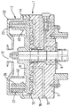
- a compound vacuum pump includes a regenerative section 1 and a Holweck section 2.
- the pump includes a housing 3 made from a number of different body parts bolted or otherwise fixed together and provided with relevant seals therebetween in a manner known per se.
- a shaft 6 mounted within the housing 3 is a shaft 6 supported by bearings, said shaft being rotatable about its longitudinal axis and driven by an electric motor surrounding the shaft 6.
- a rotor 9 which overlies a body portion 16 of the housing 3.
- a body portion 22 which forms the stator of the Holweck section 2.
- the body portion 22 includes a central inlet 31 for the Holweck section 2.
- a hollow annular cylinder 23 whose longitudinal axis is parallel to the longitudinal axis of the shaft 6 and the rotor 9.
- Each of the cylinders 23, 26, 27 is mounted symmetrically about the main axis, that is, the longitudinal axis of the shaft 6 and, as shown, the cylinders are interleaved thereby to form a uniform gap between each adjacent cylinder. This gap, however, reduces from the innermost adjacent cylinder 26 to the outermost adjacent cylinder 27.
- a threaded flange (or flanges) which define a helical structure extending substantially across the gap.
- This flange can be attached at either of the adjacent cylinders in a manner known per se.
- the rotor 9 is in the form of a disc the lower (as shown) surface of which has formed thereon a plurality of raised rings 10, which, as is known in the art, form part of the regenerative section 1 details of which form no part of this invention.
- means associated with the Holweck section 2 is provided for separating and trapping dust and other foreign bodies within the Holweck section 2 and before the said dust or other foreign bodies can reach the inlet section of the regenerative section 1.
- the radially innermost rotating cylinder 26 has formed on its inner surface an annular abutment 40 which acts to cause any dust and foreign particles entering the inlet 31 and into the recess inside the Holweck stages be trapped by the abutment 40 as the flow of the gases passes up the inner surface of the vane 26.
- a circular barrier 42 depending from body portion 22 in a direction towards the upper (as shown) surface of the rotor 9.
- centrifugal dust trap is shown downstream of the Holweck stages but before the inlet stage of the regenerative section 1.
- the centrifugal dust trap consists of a cavity 44 formed in the body portion 22 and a radially extending blade 46 mounted for rotational movement on the cylinder 27 for rotation therewith.
- centrifugal dust trap may be used on its own or together with the abutment 40 to minimise the risk of any dust reaching the inlet stage of the regenerative section 1.
- stator cylinder 23 is shown interleaved with two rotating cylinders 26, 27 clearly any practical number of stator and rotating cylinders can be used.
Landscapes
- Engineering & Computer Science (AREA)
- Mechanical Engineering (AREA)
- General Engineering & Computer Science (AREA)
- Non-Positive Displacement Air Blowers (AREA)
- Structures Of Non-Positive Displacement Pumps (AREA)
Applications Claiming Priority (2)
| Application Number | Priority Date | Filing Date | Title |
|---|---|---|---|
| GB0013491 | 2000-06-02 | ||
| GBGB0013491.6A GB0013491D0 (en) | 2000-06-02 | 2000-06-02 | Improved vacuum pump |
Publications (2)
| Publication Number | Publication Date |
|---|---|
| EP1160459A2 true EP1160459A2 (de) | 2001-12-05 |
| EP1160459A3 EP1160459A3 (de) | 2003-01-22 |
Family
ID=9892903
Family Applications (1)
| Application Number | Title | Priority Date | Filing Date |
|---|---|---|---|
| EP01304799A Withdrawn EP1160459A3 (de) | 2000-06-02 | 2001-05-31 | Vakuumpumpe |
Country Status (4)
| Country | Link |
|---|---|
| US (1) | US6626639B2 (de) |
| EP (1) | EP1160459A3 (de) |
| JP (1) | JP2002013498A (de) |
| GB (1) | GB0013491D0 (de) |
Families Citing this family (6)
| Publication number | Priority date | Publication date | Assignee | Title |
|---|---|---|---|---|
| GB0229352D0 (en) * | 2002-12-17 | 2003-01-22 | Boc Group Plc | Vacuum pumping arrangement and method of operating same |
| GB0329034D0 (en) * | 2003-12-15 | 2004-01-14 | Boc Group Plc | Vacuum pumping arrangement |
| US20050200437A1 (en) * | 2004-03-12 | 2005-09-15 | M/A-Com, Inc. | Method and mechanism for tuning dielectric resonator circuits |
| US7500822B2 (en) * | 2004-04-09 | 2009-03-10 | Edwards Vacuum, Inc. | Combined vacuum pump load-lock assembly |
| DE102005003091A1 (de) * | 2005-01-22 | 2006-07-27 | Leybold Vacuum Gmbh | Vakuum-Seitenkanalverdichter |
| US8070419B2 (en) * | 2008-12-24 | 2011-12-06 | Agilent Technologies, Inc. | Spiral pumping stage and vacuum pump incorporating such pumping stage |
Family Cites Families (7)
| Publication number | Priority date | Publication date | Assignee | Title |
|---|---|---|---|---|
| US4323369A (en) | 1979-05-07 | 1982-04-06 | Donaldson Company, Inc. | Air cleaner and ventilator |
| EP0129709A3 (de) * | 1983-04-26 | 1985-03-06 | Anelva Corporation | Kombinierte, leicht zu reinigende Molekularpumpe |
| FR2611819B1 (fr) * | 1987-02-25 | 1989-05-05 | Cit Alcatel | Pompe a vide, rotative |
| GB9609281D0 (en) * | 1996-05-03 | 1996-07-10 | Boc Group Plc | Improved vacuum pumps |
| US5709528A (en) * | 1996-12-19 | 1998-01-20 | Varian Associates, Inc. | Turbomolecular vacuum pumps with low susceptiblity to particulate buildup |
| GB9810872D0 (en) * | 1998-05-20 | 1998-07-22 | Boc Group Plc | Improved vacuum pump |
| US5921746A (en) * | 1998-10-14 | 1999-07-13 | Ford Motor Company | Fuel pump chamber with contamination control |
-
2000
- 2000-06-02 GB GBGB0013491.6A patent/GB0013491D0/en not_active Ceased
-
2001
- 2001-05-31 EP EP01304799A patent/EP1160459A3/de not_active Withdrawn
- 2001-06-01 US US09/872,930 patent/US6626639B2/en not_active Expired - Fee Related
- 2001-06-01 JP JP2001166669A patent/JP2002013498A/ja active Pending
Also Published As
| Publication number | Publication date |
|---|---|
| US6626639B2 (en) | 2003-09-30 |
| EP1160459A3 (de) | 2003-01-22 |
| JP2002013498A (ja) | 2002-01-18 |
| US20020018712A1 (en) | 2002-02-14 |
| GB0013491D0 (en) | 2000-07-26 |
Similar Documents
| Publication | Publication Date | Title |
|---|---|---|
| JP4395210B2 (ja) | 真空ポンプの改良 | |
| EP0959253B1 (de) | Vakuumpumpe | |
| EP0805275B1 (de) | Vakuumpumpe | |
| US5709528A (en) | Turbomolecular vacuum pumps with low susceptiblity to particulate buildup | |
| JP4805515B2 (ja) | 動力学的なシール部材 | |
| JP2994005B2 (ja) | 少なくとも1つの出口側のねじ段を備えたガス摩擦ポンプ | |
| JP2002515568A (ja) | ステータとロータを備えた摩擦真空ポンプ | |
| US5611660A (en) | Compound vacuum pumps | |
| EP0445855A1 (de) | Verbesserte Turbomolekularpumpe | |
| EP1170508A1 (de) | Gasreibungspumpe | |
| JP4667043B2 (ja) | 真空ポンプ排出装置 | |
| JP4584420B2 (ja) | 真空ポンプ | |
| EP1085214B1 (de) | Vakuumpumpen | |
| EP1160459A2 (de) | Vakuumpumpe | |
| CA2545566A1 (en) | Multi-stage friction vacuum pump | |
| JPH081190B2 (ja) | 回転式真空ポンプ | |
| JPH07217586A (ja) | ターボ真空ポンプ | |
| JPS58197497A (ja) | タ−ボ分子ポンプ | |
| JPH0538388U (ja) | 真空ポンプ | |
| JPH05215094A (ja) | 渦流型流体機械 | |
| HK1000016B (en) | Improved turbomolecular pump | |
| JPH065076B2 (ja) | ターボ分子ポンプ |
Legal Events
| Date | Code | Title | Description |
|---|---|---|---|
| PUAI | Public reference made under article 153(3) epc to a published international application that has entered the european phase |
Free format text: ORIGINAL CODE: 0009012 |
|
| AK | Designated contracting states |
Kind code of ref document: A2 Designated state(s): AT BE CH CY DE DK ES FI FR GB GR IE IT LI LU MC NL PT SE TR |
|
| AX | Request for extension of the european patent |
Free format text: AL;LT;LV;MK;RO;SI |
|
| PUAL | Search report despatched |
Free format text: ORIGINAL CODE: 0009013 |
|
| AK | Designated contracting states |
Kind code of ref document: A3 Designated state(s): AT BE CH CY DE DK ES FI FR GB GR IE IT LI LU MC NL PT SE TR |
|
| AX | Request for extension of the european patent |
Free format text: AL;LT;LV;MK;RO;SI |
|
| RIC1 | Information provided on ipc code assigned before grant |
Free format text: 7F 04D 19/04 A, 7F 04D 29/70 B, 7F 04D 17/16 B |
|
| 17P | Request for examination filed |
Effective date: 20030708 |
|
| AKX | Designation fees paid |
Designated state(s): AT BE CH CY DE DK ES FI FR GB GR IE IT LI LU MC NL PT SE TR |
|
| STAA | Information on the status of an ep patent application or granted ep patent |
Free format text: STATUS: THE APPLICATION IS DEEMED TO BE WITHDRAWN |
|
| 18D | Application deemed to be withdrawn |
Effective date: 20041201 |