EP1160652A2 - Tastatur - Google Patents
Tastatur Download PDFInfo
- Publication number
- EP1160652A2 EP1160652A2 EP01112786A EP01112786A EP1160652A2 EP 1160652 A2 EP1160652 A2 EP 1160652A2 EP 01112786 A EP01112786 A EP 01112786A EP 01112786 A EP01112786 A EP 01112786A EP 1160652 A2 EP1160652 A2 EP 1160652A2
- Authority
- EP
- European Patent Office
- Prior art keywords
- key
- switch
- signal
- key code
- code signal
- Prior art date
- Legal status (The legal status is an assumption and is not a legal conclusion. Google has not performed a legal analysis and makes no representation as to the accuracy of the status listed.)
- Ceased
Links
Images





Classifications
-
- G—PHYSICS
- G06—COMPUTING OR CALCULATING; COUNTING
- G06F—ELECTRIC DIGITAL DATA PROCESSING
- G06F3/00—Input arrangements for transferring data to be processed into a form capable of being handled by the computer; Output arrangements for transferring data from processing unit to output unit, e.g. interface arrangements
- G06F3/01—Input arrangements or combined input and output arrangements for interaction between user and computer
- G06F3/02—Input arrangements using manually operated switches, e.g. using keyboards or dials
- G06F3/023—Arrangements for converting discrete items of information into a coded form, e.g. arrangements for interpreting keyboard generated codes as alphanumeric codes, operand codes or instruction codes
-
- G—PHYSICS
- G06—COMPUTING OR CALCULATING; COUNTING
- G06F—ELECTRIC DIGITAL DATA PROCESSING
- G06F3/00—Input arrangements for transferring data to be processed into a form capable of being handled by the computer; Output arrangements for transferring data from processing unit to output unit, e.g. interface arrangements
- G06F3/01—Input arrangements or combined input and output arrangements for interaction between user and computer
- G06F3/02—Input arrangements using manually operated switches, e.g. using keyboards or dials
- G06F3/0202—Constructional details or processes of manufacture of the input device
- G06F3/021—Arrangements integrating additional peripherals in a keyboard, e.g. card or barcode reader, optical scanner
- G06F3/0213—Arrangements providing an integrated pointing device in a keyboard, e.g. trackball, mini-joystick
Definitions
- the present invention relates to a keyboard apparatus available for a surveillance system, and more particularly to a keyboard apparatus equipped with a joystick of the type having a switch mounted thereon.
- the conventional keyboard apparatuses of this type have so far been used for such a surveillance system available for watching unqualified people and other intruders intruding into a special room which does not permit people with any permission from entering.
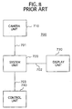
- a prior-art surveillance system 700 which comprises a camera unit 710, a display unit 730 for displaying an image taken by the camera unit 710, and a control unit 740 for controlling the operation of the camera unit 710 in response to operation commands inputted therein.
- the camera unit 710 When the camera unit 710 is operated to take an image to be displayed on the screen of the display unit 730, the camera unit 710 is firstly driven by the control unit 740 to transform the image into an image signal outputted to a signal transmitting cable 701. The image signal thus outputted to the signal transmitting cable 701 is then transmitted to a system unit 720 before being inputted to the display unit 730.
- the image signal is then transformed into an image to be displayed on the screen of the display unit 730.
- the control unit 740 is operated to receive the operation commands respectively indicative of the photographing directions, magnifications and the like inputted by an operator while he or she is watching the screen of the display unit 730.
- the control unit 740 inputted with the operation commands is then operated to transform the operation commands into a command signal to be transmitted to a signal transmitting cable 703.
- the command signal thus transmitted to the signal transmitting cable 703 is then inputted to the system unit 720 where the command signal is then transformed into a drive signal to drive the camera unit 710 to be outputted to the camera unit 710 by way of the signal transmitting cable 701.
- the camera unit 710 thus received the drive signal from the system unit 720 is at this time operated to change the photographing directions, magnifications and the like into new ones.
- such a conventional surveillance system 800 is as shown in FIG. 9 to comprise a plurality of camera units 810, a system unit 820, a plurality of display units 830, and a plurality of control units 840.
- the conventional surveillance system 800 thus constructed allows an operator to selectively operate those control units 840 to input to control units 840 operation commands indicative of selecting one or more camera units 810 and one or more display units 830. This leads to the fact that the operator can select one or more control units 840 not only to have the image displayed on the screen of one or more display units 830 in accordance with the image taken by one or more selected camera units 810 but to operate the camera units 810 under the operation states optioned by the operator.
- a CCTV Compact Circuit Television
- a joystick designed to input operation commands by an operator to ensure that a camera unit is operated under various operation states changed in photographing directions, magnifications and the like.
- Such a joystick usually has a switch to input the operation commands for example having lenses automatically focus an image.
- the conventional keyboard apparatus encounters such a problem that the change of the content of the operation commands to the joystick and the switch is performed by a software frequently changed with its new version, resulting from the fact that the content of the operation commands to be inputted by the joystick and the switch by some operators is different from those by other operators.
- the conventional keyboard apparatus can change the contents of the operation commands depending upon the needs by the operators, however, encounters complicated management to various kinds of software to be changed in compliance with the needs by the operators. In this sense, the conventional keyboard apparatus is in no practical use.
- an object of the present invention to provide a keyboard apparatus which facilitates to change the contents of the operation commands depending upon the needs by the operators to allow the operator to readily operate a joystick and a switch operatively mounted thereon.
- a keyboard apparatus for controlling and operating at least one exterior appliance, comprising: a key retainer; a plurality of keys each operatively arranged on the key retainer to perform a key-pushed action and a key-released action, each of the keys being operative to input a signal indicative of the key-pushed action; a joystick journally provided in association with the keys to input a signal indicative of the movement thereof; a switch operatively supported on the joystick and movable with respect to the joystick to selectively perform a switch-on action and a switch-off action; switch signal inputting means for inputting a switch signal indicative of the switch-on action when the switch is operated and moved to perform the switch-on action with respect to the joystick; key code signal inputting means for inputting a key code signal indicative of the key-pushed action when each of the keys is operated and moved to perform the key-pushed action; information recording means for recording specific relevant information between the switch signal inputted from the switch signal inputting means and the key code signal
- the keyboard apparatus may further comprise a display unit for displaying the specific relevant information between the switch signal and the key code signal formed when the specific key is brought into the key-pushed action.
- the key code signal inputting means may include a plurality of numerical keys which are selectively combined to form a plurality of desired key codes.
- the key code signal inputting means may include a plurality of keys which are selectively combined to form a plurality of desired key codes.
- the state setting means may include a first operation state holding key for allowing the signal processing means to assume the first operation state, and a second operation state holding key for allowing the signal processing means to assume the second operation state.
- the information recording means may be operated by the exterior appliance to record therein the specific relevant information between the switch signal and the key code signal.
- the joystick and the switch may have respective axis held in coaxial relationship with each other, and the joystick having an upper surface and the switch being resiliently urged to project upwardly of the upper surface of the joystick under the switch-off action.
- the keyboard apparatus 100 comprises a key retainer 250, and a plurality of keys operatively arranged on the key retainer 250 to perform a key-pushed action and a key-released action. Each of the keys is operative to input a signal indicative of the key-pushed action.
- the keys includes a plurality of ordinary keys such as for example numerical keys 320 and alphabetical keys, and a plurality of function keys such as for example, a PRE key 151 and a CAMERA key 152, the latter two of which will be described in more detail hereinafter. All the keys have respective key tops each indicated by a specific number or letter as shown in FIG. 1.
- the keyboard apparatus 100 further comprises a joystick 110 journally mounted on the key retainer 250 to input a signal indicative of the movement thereof, and a switch 111 operatively supported on the joystick 110 and movable with respect to the joystick 110 to selectively perform a plurality of switching actions consisting of a switch-on action and a switch-off action.
- the joystick 110 and the switch 111 have respective axis held in coaxial relationship with each other.
- the joystick 110 has an upper surface, and the switch 111 is resiliently urged to project upwardly of the upper surface of the joystick 110 under the switch-off action.
- the joystick 110 may be provided on a retaining member separated from the key retainer 250, but is required to be provided in association with the keys.
- the above construction of the joystick 110 and the switch 111 enables an operator to grip the joystick 110 with his or her finger placed on the switch 111 as shown in phantom lines in FIG. 2 to ensure that the joystick 110 is readily moved and inclined in all directions while the switch 111 is pushed by his or her finger. This makes it possible for the operator to operate the joystick 110 and the switch 111 by one hand.
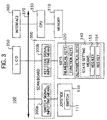
- the keyboard apparatus 100 further comprises a scan board 300, a memory 310, a central processing unit 330, hereinafter simply referred to as "CPU”, a liquid crystal display 350, hereinafter simply referred to as “LCD”, an interface 360, and a bus 370 electrically connected to the scan board 300, the memory 310, the CPU 330, the LCD 350, and an interface 360.
- the scan board 300, the memory 310, the CPU 330, the LCD 350, and the interface 360 are accommodated in the key retainer 250, while the LCD 350 has a screen having a screen surface flush with the upper surface of the key retainer 250 and is partly housed in the key retainer 250.
- the keyboard apparatus 100 further comprises switch signal inputting means 300a and key code signal inputting means 300b which are partly provided in the scan board 300.
- the switch signal inputting means 300a is designed to input a switch signal indicative of the switch-on action when the switch 111 is operated and moved to perform the switch-on action with respect to the joystick 110.
- the key code signal inputting means 300b is adapted to input a key code signal indicative of the key-pushed action when each of the keys are operated and moved to perform the key-pushed action.
- a plurality of numerical keys 320 are used for forming one of the key codes. For example, the numerical keys 320 "0", "4" and "8" pushed in this order cause a key code "048" to be formed for a key code signal.
- any number of numerical keys 320 may be used for forming a key code, and any other key or keys such as alphabetical or function key or keys may replace the numerical key or keys.
- the key code signal inputting means 300b is constituted by the part of the scan board 300 and the keys.
- the key code signal inputting means 300b may include a plurality of numerical keys 320 which are selectively combined to form a plurality of desired key codes according to the present invention. Also, the key code signal inputting means 300b may replace the numerical keys 320 and thus may include a plurality of ordinary keys other than the numerical keys 320. The ordinary keys can be selectively combined to form a plurality of desired key codes in a similar manner to the numerical keys 320.
- the keyboard apparatus 100 further comprises information recording means constituted by the memory 310 which is designed to record specific relevant information between the switch signal inputted from the switch signal inputting means 300a and the key code signal inputted from the key code signal inputting means 300b.
- the specific relevant information is formed by at least one specific key selected from among the keys and brought into the key-pushed action.
- the key includes numerical, alphabetical and any other keys the operator wishes to select.
- the specific relevant information may be formed by a plurality of specific keys selected from among the keys and brought into the respective key-pushed actions. Further, the keys include numerical, alphabetical and any other keys the operator wishes to select.
- the memory 310 is adapted to allow the CPU 330 to record the specific relevant information therein and to read out the specific relevant information into the CPU 330 therefrom.
- the keyboard apparatus 100 further comprises signal processing means constituted by the CPU 330 which is operated to receive and process the switch signal from the switch signal inputting means 300a and the key code signal from the key code signal inputting means 300b.
- the signal processing means i.e., the CPU 330 is operative to selectively assume two different operation states consisting of a first operation state under which the specific relevant information is recorded by the memory 310 in accordance with the switch signal inputted by the switch signal inputting means 300a and the key code signal inputted by the key code signal inputting means 300b, and a second operation state under which the key code in response to the switch signal from the switch signal inputting means 300a are outputted to the exterior appliance 390 in accordance to the specific relevant information recorded by the memory 310.
- the keyboard apparatus 100 further comprises state setting means 340 for selectively setting the first and second operation states of the CPU 330.
- the state setting means 340 includes a first operation state holding key, such as for example a REG key 153, for allowing the CPU 330 to assume the first operation state, and a second operation state holding key, such as for example a RES key 154, for allowing the CPU 330 to assume the second operation state.
- the key-pushed actions of the first and second state holding keys 153 and 154 cause the CPU 330 to be operated to hold the first and second operation states, respectively.
- the state setting means 340 is thus constituted by the CPU 330 and the first and second state holding keys.
- the keyboard apparatus 100 further comprises a display unit constituted by the LCD 350 which is operated to display the specific relevant information between the switch signal and the key code signal formed when the specific keys are under the key-pushed actions.
- the display unit i.e., the LCD 350 serves to have the operator readily confirm his or her operation conditions of the exterior appliance 390 through the screen of the LCD 350.
- the interface 360 is adapted to allow the key code signal in response to the switch signal from the switch signal inputting means 300a to be outputted through a signal transmitting cable 391 to the exterior appliance 390 such as for example watching cameras by the key code signal inputting means 300b in accordance to the specific relevant information recorded by the memory 310.
- FIG. 1 there are shown keys bearing respective key tops for example represented by the letters “REG”, “RES”, “PRE”, “CAMERA” and numbers "0" to "9".
- keys other than the above keys have respective key tops having in reality their own letters that are not shown in FIGS. 1 and 7.
- FIGS. 4 and 5 show steps to be performed by one of the preferred embodiments of the keyboard apparatus 100 according to the present invention, however, the steps according to the present invention are not limited to these steps.
- the keyboard apparatus 100 is operated to have the keys other than the REG key 153 pushed to input the key code signals indicative of the key codes in response to the pushed keys to the exterior appliance 390 through the interface 360.
- the PRE key 151 is raised as a key other than the REG key 153 for the operator to operate.
- steps S401 and S405 the CPU 330 is held in a condition to have the key code signal outputted from the CPU 330, and thus under its condition waiting for either the switch signal or the key code signal until any one of the switch signal and the key code signal is inputted into the CPU 330.
- the steps S401 and S405 are repeated when the switch signals and the key code signals are not inputted into the CPU 330.
- the scan board 300 When the operator then pushes the PRE key 151, the scan board 300 is operated to output the key code signal indicative of the key-pushed action of the PRE key 151 to the bus 370.
- the key code signal thus outputted to the bus 370 is then inputted to the CPU 330 through the bus 370.
- the CPU 330 With the key code signal inputted to the CPU 330, the CPU 330 is operated to determine whether the operator pushes the REG key 153 or not in step S402.
- the CPU 330 determines that the operator pushes any key other than the REG key 153, the CPU 330 is operated to output to the bus 370 the key code signal such as for example "001" indicative of the key-pushed action of the PRE key 151 in accordance with the relevant information between the key and key code signal recorded in the memory 310 in step S403.
- the CPU 330 is again held under its condition waiting for the key code signal after the CPU 330 is operated to output to the bus 370 the key code signal "001" indicative of the key-pushed action of the PRE key 151 in step S401.
- the key code signal "001" outputted to the bus 370 is inputted into the interface 360 through the bus 370.
- the interface 360 is then operated to output the key code signal "001" to the exterior appliance 390.
- the keyboard apparatus 100 is operated to output to the exterior appliance 390 through the interface 360 a key code signal indicative of the switch-on action of the switch 111.
- steps S401 and S405 the CPU 330 is held in a condition to have the key code signal outputted from the CPU 330, and thus under its condition waiting for either the switch signal or the key code signal until any one of the switch signal and the key code signal is inputted into the CPU 330.
- the steps S401 and S405 are repeated when the switch signal and the key code signal are not inputted into the CPU 330.
- the scan board 300 When the operator then pushes the switch 111, the scan board 300 is operated to output the switch signal indicative of the switch-on action of the switch 111 to the bus 370.
- the switch signal thus outputted to the bus 370 is then inputted to the CPU 330 through the bus 370.
- the key code signal such as for example "002" indicative of the switch-on action of the switch 111 is outputted to the bus 370 by the CPU 330 in accordance to the specific relevant information recorded by the memory 310 in step S406.
- the CPU 330 After the key code signal such as for example "002" indicative of the switch-on action of the switch 111 is outputted to the bus 370, the CPU 330 is again held under its condition waiting for the key code signal in step S401.
- the key code signal "002" outputted to the bus 370 is inputted into the interface 360 through the bus 370.
- the interface 360 is then operated to output the key code signal "002" to the exterior appliance 390 such as a camera.
- the keyboard apparatus 100 is operated to output to the exterior appliance 390 through the interface 360 a key code signal indicative of the switch-on action of the switch 111 which is to be changed to have another operation command.
- the following example is directed to the case that the switch 111 is assigned to have an operation command inputted into the CPU 330, the operation command being identical to the operation command generated with the PRE key 151 and the CAMERA key 152 concurrently held in the respective key-pushed actions.
- the keyboard apparatus 100 is assumed to be used in combination with a surveillance system which comprises a plurality of watching cameras bearing respective numbers different from each other.
- the concurrent key-pushed actions of the PRE key 151 and the CAMERA key 152 are performed to produce an image on the screen of the LCD 350 which is identical to the image taken by the camera bearing its number smaller than that of the camera.
- the switch-on action of the switch 111 can produce an image on the screen of the LCD 350 which is identical to the image taken by the camera bearing its number smaller than that: of the camera.
- the keyboard apparatus 100 can transfer the functions of the PRE key 151 and the CAMERA key 152 to the switch 111 so that the joystick 110 and the switch 111 can readily be operated by one hand. This makes it possible for the operator to operate the joystick 110 to displace the cameras or change the directions of the cameras while concurrently operating the switch 111 to move one camera to other cameras. It is thus to be understood that the keyboard apparatus 100 according to the present invention enables to enhance its operability to a higher level than that of the conventional keyboard apparatus.
- the following description is directed to how the keyboard apparatus 100 can transfer the functions of the PRE key 151 and the CAMERA key 152 to the switch 111 to ensure that the joystick 110 and the switch 111 can readily be operated by one hand.
- steps S401 and S405 the CPU 330 is held in a condition to have the key code signal outputted from the CPU 330, and thus under its condition waiting for either the switch signal or the key code signal until any one of the switch signal and the key code signal is inputted into the CPU 330. Therefore, the condition of the CPU 330 includes a second operation state under which the key code signal in response to the switch signal from the switch 111 is outputted to the exterior appliance 390 in accordance to the specific relevant information recorded by the memory 310.
- the steps S401 and S405 are repeated when the switch signal and the key code signal are not inputted into the CPU 330.
- the scan board 300 When the operator then pushes the REG key 153, the scan board 300 is operated to output the key code signal indicative of the key-pushed action of the REG key 153 to the bus 370.
- the key code signal thus outputted to the bus 370 is then inputted to the CPU 330 through the bus 370.
- the CPU 330 With the key code signal inputted to the CPU 330, the CPU 330 is operated to determine whether the operator pushes the REG key 153 or not in step S402.
- the CPU 330 determines that the operator pushes the REG key 153, the CPU 330 is operated to perform a routine to a first operation state in step S404. Under the first operation state, the CPU 330 has the first operation state routine performed while having the second operation state routine stopped. This means that the CPU 330 is held under its condition under which the specific relevant information is recorded by the memory 310 in accordance with the switch signal inputted by the switch signal inputting means 300a and the key code signal inputted by the key code signal inputting means 300b in steps S411 and S413.
- the condition of the CPU 330 lasts until either the switch signal or the key code signal is inputted into the CPU 330.
- the operator operates the numerical keys 320 to input the numbers "003", i.e., the key code "003" with the PRE key 151 and the CAMERA key 152 concurrently pushed by the operator.
- the key code "003" thus inputted by the operator is outputted to the bus 370 through the scan board 300 in the form of a key code signal indicative of the key-pushed actions of the numerical keys 320.
- the key code "003" thus outputted to the bus 370 is inputted to the CPU 330. Under these conditions, the CPU 330 is held under its condition waiting for the switch signal from the switch 111 in step S412.
- the switch 111 pushes the switch 111.
- the scan board 300 is operated to output the switch signal indicative of the switch-on action of the switch 111 to the bus 370.
- the switch signal indicative of the switch-on action of the switch 111 thus outputted is inputted to the CPU 330 through the bus 370.
- the CPU 330 is held under its condition waiting for the key code signal from the RES key 154 in step S415.
- the scan board 300 is operated to input the key code signal indicative of the key-pushed action of the RES key 154 to the CPU 330 through the bus 370.
- the CPU 330 is operated to have the specific relevant information between the switch signal of the switch 111 and the key code signal indicative of the key code "003" recorded by the memory 310 in step S416.
- the CPU 330 With the specific relevant information thus recorded by the memory 310, the CPU 330 is then operated to have the routine of the first operation state return to the starting state. After the routine of the first operation state is returned by the CPU 330 to the starting state, the CPU 330 is operated to end the first operation state of the memory 310, i.e., the information recording means and to resume the second operation state under which the key code signal in response to the switch signal from the switch signal inputting means 300a are outputted to the exterior appliance 390 in accordance to the specific relevant information recorded by the memory 310.
- the keyboard apparatus can facilitate to change key code signals, i.e., the contents of the operation commands depending upon the needs by the operator to allow the operator to readily operate the joystick and the switch.
- the key code signal may be inputted to the CPU 330 after the switch signal is inputted to the CPU 330 according to the present invention.
- the CPU 330 is operated to carry out the steps S413 and S414 in place of the steps S411 and S412.
- the above specific relevant information may include another specific relevant information between the switch signal indicative of the switch-on action of the switch 111 and another key code signal indicative of a key code such as for example a key code "000" which does not work the specific relevant information recorded in the memory 310.
- the specific relevant information recorded in the memory 310 to have the switch signal indicative of the switch-on action of the switch 111 and the key code signal indicative of the key code "000” cause the keyboard apparatus 100 to be operated to output through the interface 360 the key code signal indicative of the key code "000” which does not: work the specific relevant information recorded in the memory 310.
- This means that the alternative embodiment is in reality tantamount to a keyboard apparatus which has no switch on the joystick 110.
- the keyboard apparatus 100 comprises a LCD 350 can display the specific relevant information recorded in the memory 310 about the switch signal indicative of the switch 111 and the key code signal indicative of the key code with the predetermined operation by the operator leads to the fact that the operator can confirm through the screen of the LCD 350 the content of the operation command effected by the switch 111 on the joystick 110 to ensure that the content of the operation command is readily and reliably changed by the switch 111 on the joystick 110.
- any other keys may be used in lieu of the numerical keys 320 according to the present invention as will be seen from the following embodiment.
- the alternative embodiment of the keyboard apparatus may comprise key code signal inputting means 300b constituted by a LCD 350 and a joystick 110 to ensure that the key code is displayed on the screen of the LCD 350 under the first operation state of the CPU 330 to have the specific relevant information recorded in the memory 310.
- the LCD 350 may display numbers constituting a key code in such a manner that the number is increased as the joystick 110 is moved in one direction while the number is decreased as the joystick 110 is moved in the other direction.
- the key code signal inputting means 300b forming part of the alternative embodiment ensures that any desired keys pushed by the operator allow the key codes corresponding to the pushed keys to be inputted in the form of a key code signal.
- the state setting means 340 includes a REG key 153 retained by the key retainer 250 and forming a first operation state holding key for allowing the CPU 330 to assume the first operation state, and a RES key 154 retained by the key retainer 250 and forming a second operation state holding key for allowing the CPU 330 to assume the second operation state
- the keyboard apparatus 100 may be constituted by any other means as long as the state setting means 340 can allow the CPU 330 to assume either the first operation state or the second operation state.
- the previous keyboard apparatus 100 does not need such a RES key 154 forming part of the state setting means 340 if the switch signal and the key code signal are concurrently inputted to the CPU 330 to hold the CPU 330 under the first operation state under which the specific relevant information between the switch signal and the key code signal is recorded by the memory 310 in response to the switch signal and the key code signal before the CPU 330 is held under the second operation state under which the key code signal in response to the switch signal are outputted in accordance to the specific relevant information recorded by the memory 310.
- the keyboard apparatus 100 may be constituted in combination with the exterior appliance 390 to have the CPU 330 and the memory 310 wherein the CPU 330 is operative to have the specific relevant information between the switch signal and the key code signal recorded by the memory 310 from the exterior appliance 390 and to have the specific relevant information in the memory 310 recorded by the exterior appliance 390.
- the foregoing keyboard apparatus 100 ensures that the CPU 330 enables the specific relevant information to be exchanged between the memory 310 and the exterior appliance 390.
- the specific relevant information recorded by the exterior appliance 390 can readily be transferred to and recorded by the memory 310 for a new keyboard apparatus 100 changed by the old keyboard apparatus 100.
- the keyboard apparatus 100 has been described with reference to an example in which the content of the operation command inputted through the switch 111 can be changed by the content of the operation command which is the same as the content of the operation command inputted by the PRE key 151 and the CAMERA key 152 held in their concurrently key-pushed actions, however, the content of the operation command inputted through the switch 111 can freely be changed by the operator according to the present invention.
- the joystick 110 can be used for the recording and reproducing machine if the switch 111 is operative to input the operation command changed by the operator so that the joystick 110 is operated to be inclined in any directions while the switch 111 is being held in the switch-on action for the purpose of operating the recording and reproducing machine, although the joystick 110 is usually used to operate the recording and reproducing machine in the manner previously mentioned. More specifically, the keyboard apparatus 100 thus constructed renders it possible for the operator to incline the joystick 110 in the directions as shown by arrows 371, 372, 373 and 374 in FIG. 7 to ensure that the operation commands such as intermittently forwarding, intermittently rewinding, fast-forwarding and rewinding are fed to the recording and reproducing machine.
- the keyboard apparatus according to the present invention makes it possible for the operator to change into his or her desired content the content of the operation command to be inputted through the switch on the joystick simply by operating the keys on the key retainer.
- the keyboard apparatus according to the present invention can thus bring about such an advantage that the change of the content of the operation commands to the joystick and the switch is readily changed only by operating the keys on the keyboard and the switch on the joystick. This leads to the fact that there is no need for various kinds of software to be prepared for the conventional apparatus which is used by many operators. It is to be appreciated that the keyboard apparatus according to the present invention does not need complicated management to various kinds of software required for the conventional apparatus and is therefore extremely useful for operators.
Landscapes
- Engineering & Computer Science (AREA)
- General Engineering & Computer Science (AREA)
- Theoretical Computer Science (AREA)
- Human Computer Interaction (AREA)
- Physics & Mathematics (AREA)
- General Physics & Mathematics (AREA)
- Input From Keyboards Or The Like (AREA)
- Position Input By Displaying (AREA)
- Closed-Circuit Television Systems (AREA)
Applications Claiming Priority (2)
| Application Number | Priority Date | Filing Date | Title |
|---|---|---|---|
| JP2000157030A JP2001337776A (ja) | 2000-05-26 | 2000-05-26 | キーボード装置 |
| JP2000157030 | 2000-05-26 |
Publications (2)
| Publication Number | Publication Date |
|---|---|
| EP1160652A2 true EP1160652A2 (de) | 2001-12-05 |
| EP1160652A3 EP1160652A3 (de) | 2008-06-25 |
Family
ID=18661731
Family Applications (1)
| Application Number | Title | Priority Date | Filing Date |
|---|---|---|---|
| EP01112786A Ceased EP1160652A3 (de) | 2000-05-26 | 2001-05-28 | Tastatur |
Country Status (3)
| Country | Link |
|---|---|
| US (1) | US6760011B2 (de) |
| EP (1) | EP1160652A3 (de) |
| JP (1) | JP2001337776A (de) |
Cited By (1)
| Publication number | Priority date | Publication date | Assignee | Title |
|---|---|---|---|---|
| GB2411229A (en) * | 2003-07-22 | 2005-08-24 | Hitachi Int Electric Inc | Controller for an object tracking apparatus responding to manipulation information input when a current visual field range is not a prohibited region |
Families Citing this family (7)
| Publication number | Priority date | Publication date | Assignee | Title |
|---|---|---|---|---|
| US20060176274A1 (en) * | 2003-02-25 | 2006-08-10 | Chiu-Hao Cheng | Photographic type pointer positioning device |
| KR100569677B1 (ko) | 2004-11-30 | 2006-04-10 | 엘지전자 주식회사 | 조이스틱 기능을 이용한 무선 마우스 |
| WO2006079183A1 (en) * | 2005-01-31 | 2006-08-03 | Lextar Pty Ltd | Video surveillance system controller |
| WO2006096830A2 (en) * | 2005-03-09 | 2006-09-14 | Rhett Howard E | Multiple-evaluator input device |
| JP2007243268A (ja) * | 2006-03-06 | 2007-09-20 | Sony Corp | 映像監視システムおよび映像監視プログラム |
| KR100777118B1 (ko) * | 2006-05-11 | 2007-11-19 | (주)경문엔터테인먼트 | 온라인 게임에 적합한 다기능 데이터입력장치와 그키매핑제어시스템 및 방법 |
| WO2026127783A1 (ru) * | 2024-12-12 | 2026-06-18 | Юрий Викторович РАСПОПОВ | Устройство ввода-вывода для работы на компьютере |
Citations (1)
| Publication number | Priority date | Publication date | Assignee | Title |
|---|---|---|---|---|
| WO1998057719A1 (en) | 1997-06-19 | 1998-12-23 | Act Labs Ltd. | Reconfigurable video game controller |
Family Cites Families (9)
| Publication number | Priority date | Publication date | Assignee | Title |
|---|---|---|---|---|
| US4949080A (en) * | 1988-12-12 | 1990-08-14 | Mikan Peter J | Computer keyboard control accessory |
| CA2062620C (en) * | 1991-07-31 | 1998-10-06 | Robert Paff | Surveillance apparatus with enhanced control of camera and lens assembly |
| US5838368A (en) * | 1992-06-22 | 1998-11-17 | Canon Kabushiki Kaisha | Remote camera control system with compensation for signal transmission delay |
| US5551701A (en) * | 1992-08-19 | 1996-09-03 | Thrustmaster, Inc. | Reconfigurable video game controller with graphical reconfiguration display |
| US5517236A (en) * | 1994-06-22 | 1996-05-14 | Philips Electronics North America Corporation | Video surveillance system |
| US5558329A (en) * | 1995-03-01 | 1996-09-24 | Liu; William S. Y. | Photoelectric digitized joystick |
| JP3311190B2 (ja) * | 1995-03-03 | 2002-08-05 | 株式会社東芝 | パーソナルコンピュータ |
| US6184862B1 (en) * | 1996-07-08 | 2001-02-06 | Thomas Leiper | Apparatus for audio dictation and navigation of electronic images and documents |
| JP2001337768A (ja) * | 2000-05-26 | 2001-12-07 | Matsushita Electric Ind Co Ltd | キーボード装置 |
-
2000
- 2000-05-26 JP JP2000157030A patent/JP2001337776A/ja active Pending
-
2001
- 2001-05-25 US US09/866,265 patent/US6760011B2/en not_active Expired - Fee Related
- 2001-05-28 EP EP01112786A patent/EP1160652A3/de not_active Ceased
Patent Citations (1)
| Publication number | Priority date | Publication date | Assignee | Title |
|---|---|---|---|---|
| WO1998057719A1 (en) | 1997-06-19 | 1998-12-23 | Act Labs Ltd. | Reconfigurable video game controller |
Cited By (3)
| Publication number | Priority date | Publication date | Assignee | Title |
|---|---|---|---|---|
| GB2411229A (en) * | 2003-07-22 | 2005-08-24 | Hitachi Int Electric Inc | Controller for an object tracking apparatus responding to manipulation information input when a current visual field range is not a prohibited region |
| GB2411229B (en) * | 2003-07-22 | 2006-04-12 | Hitachi Int Electric Inc | Object tracking method and object tracing apparatus |
| US7596240B2 (en) | 2003-07-22 | 2009-09-29 | Hitachi Kokusai Electric, Inc. | Object tracking method and object tracking apparatus |
Also Published As
| Publication number | Publication date |
|---|---|
| US6760011B2 (en) | 2004-07-06 |
| US20010048427A1 (en) | 2001-12-06 |
| JP2001337776A (ja) | 2001-12-07 |
| EP1160652A3 (de) | 2008-06-25 |
Similar Documents
| Publication | Publication Date | Title |
|---|---|---|
| JP2557358B2 (ja) | 情報処理装置 | |
| EP0737005B1 (de) | Verfahren und Vorrichtung zur Kamerakontrolle | |
| KR0149855B1 (ko) | 화상검색장치 | |
| US9116610B2 (en) | Imaging apparatus and user interface | |
| US6122003A (en) | Method and apparatus for changing operating modes of an image capture device | |
| US20020146250A1 (en) | Information switch and method for a digital camera | |
| JPS63163924A (ja) | 情報処理装置 | |
| US7768573B2 (en) | Optical apparatus and image-taking apparatus | |
| US6262709B1 (en) | Letter input apparatus and method | |
| US6760011B2 (en) | Keyboard apparatus | |
| EP0863475A2 (de) | Zeichenerkennungsvorrichtung | |
| US6686905B2 (en) | Keyboard apparatus | |
| US5138702A (en) | External image input/output device connectable image processing system | |
| US4809041A (en) | Image forming apparatus with storage of processing modes | |
| JP2005150878A (ja) | 携帯型情報処理装置、情報処理方法 | |
| US20070109261A1 (en) | Information processing method and information processing apparatus | |
| JP4480099B2 (ja) | 表示制御装置 | |
| JP2004077706A (ja) | レンズシステム | |
| JP2000188792A (ja) | キ―共有方法及び同一機能共有方法 | |
| KR100530802B1 (ko) | 전자 카메라의 메뉴 출력 제어 장치 및 그 방법 | |
| JPS63102461A (ja) | 電子フアイル装置における入力装置 | |
| JP2008083861A (ja) | 画像投影装置及び画像投影システム | |
| JPH05103376A (ja) | 遠隔制御装置 | |
| JPH05236317A (ja) | 雲台を用いたテレビカメラ動作制御装置 | |
| JP2000261590A (ja) | 直結装置 |
Legal Events
| Date | Code | Title | Description |
|---|---|---|---|
| PUAI | Public reference made under article 153(3) epc to a published international application that has entered the european phase |
Free format text: ORIGINAL CODE: 0009012 |
|
| AK | Designated contracting states |
Kind code of ref document: A2 Designated state(s): AT BE CH CY DE DK ES FI FR GB GR IE IT LI LU MC NL PT SE TR |
|
| AX | Request for extension of the european patent |
Free format text: AL;LT;LV;MK;RO;SI |
|
| PUAL | Search report despatched |
Free format text: ORIGINAL CODE: 0009013 |
|
| AK | Designated contracting states |
Kind code of ref document: A3 Designated state(s): AT BE CH CY DE DK ES FI FR GB GR IE IT LI LU MC NL PT SE TR |
|
| AX | Request for extension of the european patent |
Extension state: AL LT LV MK RO SI |
|
| 17P | Request for examination filed |
Effective date: 20080807 |
|
| 17Q | First examination report despatched |
Effective date: 20081007 |
|
| RAP1 | Party data changed (applicant data changed or rights of an application transferred) |
Owner name: PANASONIC CORPORATION |
|
| AKX | Designation fees paid |
Designated state(s): DE FR GB |
|
| STAA | Information on the status of an ep patent application or granted ep patent |
Free format text: STATUS: THE APPLICATION HAS BEEN REFUSED |
|
| 18R | Application refused |
Effective date: 20100420 |